Advertisement
Available languages
Available languages
Quick Links
iMpOrtaNt:
NOtE: DO NOt rEtUrN UNit tO tHE StOrE
BEFOrE cONtactiNG OUr cUStOMEr SErVicE
DEpartMENt. DO NOt DiSpOSE OF yOUr
cartONS UNtil yOU arE cOMplEtEly SatiSFiED
witH yOUr NEw FirEplacE HEatEr.
PLEASE NOTE: WHEN YOU OPEN THE CARTON CAREFULLY CHECK THE UNIT
AND MAKE SURE THERE IS NO DAMAGE. IF YOU HAVE ANY PROBLEMS WITH
THE UNIT, WITH HOW THE VARIOUS FUNCTIONS WORK, DAMAGED OR MISSING
PARTS PLEASE CALL 1-844-455-4621 IMMEDIATELY FOR SERVICE.
NOtE: light bulbs may become loose during shipping. if the flame effect is dim or does
not work, please check that light bulb or bulbs are finger tight in socket. See instructions
for replacing bulb or bulbs.
NOtE: the electric fireplace heater may emit a slight harmless odor when first turned on.
this is caused by activating the internal heater components for the first time and should
not occur again.
INSTRUCTION MANUAL
attENtiON:
1. Find a location for the fireplace heater that is protected from direct sunlight.
2. Do not plug the unit into the power outlet before reading all instructions.
IMPORTANT SAFETY
INSTRUCTIONS
wHEN USiNG ElEctrical appliaNcES, BaSic prEcaUtiONS SHOUlD alwayS BE
FOllOwED tO rEDUcE tHE riSk OF FirE, ElEctric SHOck, aND pErSONal iNJUry,
iNclUDiNG tHE FOllOwiNG:
1) read all instructions before using this electric fireplace heater.
2) this electric fireplace heater is hot when in use. to avoid burns, do not let bare skin
touch hot surfaces. the grill directly in front of the heater outlet becomes hot during
heater operation. keep combustible materials, such as furniture, pillows, bedding,
papers, clothes, and curtains at least 3 ft (0.9 m) away from the front of the unit and
keep them away from the sides and rear.
3) Extreme caution is necessary when any heater is used by or near children or
individuals with disabilities and whenever the fireplace is left operating and
unattended.
4) always unplug the fireplace when not in use.
5) Do not operate any electric fireplace with a damaged cord or plug or after the heater
malfunctions, has been dropped or damaged in any manner.
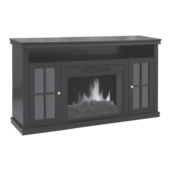
ElEctric FirEplacE HEatEr
Model: MM433L-60EBK (NDF-120B)
design forward living
6) Do not use outdoors.
7) this electric fireplace heater is not intended for use in bathrooms, laundry areas and
similar indoor locations. Never locate the heater where it may fall into a bathtub or
other water container.
8) Do not run the cord under carpeting. Do not cover the cord with throw rugs, runners,
or similar coverings. arrange the cord away from traffic areas and where it will not be
tripped over.
9) to disconnect the fireplace, turn controls to off, then remove the plug from the outlet.
10) connect to properly grounded outlets only.
11) Do not insert or allow foreign objects to enter any ventilation or exhaust opening,
as this may cause an electric shock or fire, or damage the heater.
12) to prevent a possible fire, do not block air intakes or exhaust in any manner. Do not
use on soft surfaces, like a bed, where openings may become blocked.
13) a heater has hot and arcing or sparking parts inside. Do not use it in areas where
gasoline, paint, or flammable liquids are used or stored.
14) Use this fireplace heater only as described in this manual. any other use not
recommended by the manufacturer may cause fire, electric shock, or personal
injury.
15) avoid the use of an extension cord because the extension cord may overheat and
cause a risk of fire. However, if you have to use an extension cord, the cord shall be
No.14 awG minimum size and rated not less than 1875 watts.
16) caution: Do not plug this product into a receptacle controlled by a wall switch or
dimmer.
17) when storing or transporting the unit and cord, keep in a dry place, free from
excessive vibration and store so as to avoid damage.
SAVE THESE INSTRUCTIONS
FOR FUTURE USE.
caUtiON:
iF yOU USE tHiS HEatEr iN cONJUNctiON witH a tHErMal cONtrOl, a prOGraM
cONtrOllEr, a tiMEr Or aNy OtHEr DEVicE tHat SwitcHES tHE HEatEr ON
aUtOMatically, rEMEMBEr tO OBSErVE all SaFEty warNiNGS at all tiMES. tHE
FirEplacE HEatEr HaS SaFEty OVErHEat prOtEctiON. iF tHE OVErHEat prOtEctiON
tripS, SwitcH OFF all SwitcH BUttONS aND wait apprOxiMatEly 5–10 MiNUtES. it
SHOUlD rESEt aUtOMatically ONcE tHE UNit cOOlS DOwN.
warNiNG: DO NOt lOaD MOrE tHaN 22.7 kG (50 lBS) ON tHE tOp SHElF.
warNiNG: prOcEDUrES aND tEcHNiqUES iF NOt carEFUlly FOllOwED will rESUlt iN
DaMaGE tO tHE EqUipMENt aND will ExpOSE tHE USEr tO tHE riSk OF SEriOUS iNJUry,
illNESS Or DEatH.
A 15 AMP circuit is required to operate this heater. If the breaker trips when the heater
is used, then you may need to move the heater to another location or unplug other
appliances that are on the same circuit. If you require an extension cord use one that is
rated at 1875 watts.
1
Advertisement

Related Manuals for decorflame MM433L-60EBK


Summary of Contents for decorflame MM433L-60EBK
-
Page 1: Save These Instructions
ElEctric FirEplacE HEatEr Model: MM433L-60EBK (NDF-120B) design forward living iMpOrtaNt: 6) Do not use outdoors. 7) this electric fireplace heater is not intended for use in bathrooms, laundry areas and NOtE: DO NOt rEtUrN UNit tO tHE StOrE similar indoor locations. Never locate the heater where it may fall into a bathtub or BEFOrE cONtactiNG OUr cUStOMEr SErVicE other water container. -
Page 2: Parts List
This electric fireplace heater is for use on 120 volts. The cord has a plug, as shown at A in illustration below. An adapter, as shown at C, is available for connecting three-blade grounding-type plugs to two-slot receptacles. The green grounding plug extending from the adapter must be connected to a permanent ground such as a properly grounded outlet box. - Page 3 MANTEL ASSEMBLY Step 3: Attach panels F, G, J and K to the base panel [D] with 6 long screws [W]. See Fig. C. caUtiON: Place a piece of cardboard or protective sheet on the floor in order to avoid scratching the decorative surface of your mantel during assembly.
- Page 4 Step 5: Attach the middle panel [C] to panels F, G, J and K with 6 long screws [W]. Step 8: Attach the top panel [A] to panels F and G with 4 long screws [W]. See Fig. H. See Fig. E. Fig.
- Page 5 Step 10: Slide the shelves [E] into the unit, as shown in Fig. J. Step 12: Attach the 4 door hinges [Tc] to the left door [N] and right door [O] with 8 door hinge screws [Te]. Attach the door handles [Ta] to the left and right doors with 2 door screws [Tb].
- Page 6 FIREPLACE INSERT INSTALLATION Step 15: Attach support panels Pa, Pb and Pc to panels C, J and K with 6 long screws [W]. See Fig. O. The fireplace insert can be installed after the mantel has been fully assembled. warNiNG: MakE SUrE tHE FirEplacE iNSErt cONtrOlS arE iN tHE OFF pOSitiON aND tHE UNit iS NOt plUGGED iN.
-
Page 7: Light Bulb Replacement
OPERATION MAINTENANCE warNiNG: DiScONNEct pOwEr aND UNplUG tHE pOwEr cOrD BEFOrE attEMptiNG After completely reading the instructions, confirm all the controls on the fireplace are aNy MaiNtENaNcE Or clEaNiNG tO rEDUcE tHE riSk OF FirE, ElEctric SHOck Or in the OFF position. Plug the fireplace into a 15 AMP/120 Volt outlet. If the cord does not pErSONal iNJUry. - Page 8 REPAIRS OptiON 2: Use the small L-brackets and screws. If any problems are found with the original parts during mantel assembly, such as that 1. Place the small L-bracket on the unit, as shown, and mark the drill holes on the mantel, the panels cannot be installed with the plastic connectors, try to solve by one of the as shown in Fig.
-
Page 9: Replacement Parts
REPLACEMENT PARTS itEM part # Self repair kit RE-KIT Hardware kit 433L-60-HWT#1 R) Spacers ..........4 S) Wire passage ........1 Ta) Door handles ........2 Tb) Door handle screws ......2 Tc) Door hinges ........4 WARRANTY Every electric stove is tested before it leaves the factory and it is guaranteed for one year. - Page 10 FOyEr ÉlEctriqUE Modèle : MM433L-60EBK (NDF-120B) design forward living iMpOrtaNt : 3) Faites preuve de la plus grande prudence lorsqu’un foyer est utilisé à proximité d’enfants ou de personnes invalides, ou par ceux-ci, et chaque fois que l’appareil est laissé en état rEMarqUE : NE paS rEtOUrNEr l’UNitÉ...
- Page 11 MiSE EN GarDE : Ta) Poignées de porte ....................2 Si VOUS UtiliSEz cE FOyEr cONJOiNtEMENt aVEc UNE cOMMaNDE tHErMiqUE, UN Tb) Vis pour les poignées de porte ................2 rÉGUlatEUr À prOGraMME, UNE MiNUtEriE OU qUElqUE aUtrE DiSpOSitiF qUi MEt Tc) Charnières de porte ....................
- Page 12 ASSEMBLAGE DU MANTEAU Étape 3 : Assembler les panneaux F, G, J et K au panneau de la base [D] en utilisant 6 vis longues [W]. Voir la fig. C. aVErtiSSEMENt : Placer un morceau de carton ou une couverture de protection sur le plancher afin d’éviter d’égratigner la surface du manteau de foyer pendant l’assemblage.
- Page 13 Étape 5 : Assembler le panneau central [C] aux panneaux F, G, J et K en utilisant 6 vis Étape 8 : Assembler le panneau supérieur [A] aux panneaux F et G en utilisant 4 vis longues [W]. Voir la fig. E. longues [W].
- Page 14 Étape 10 : Placer les tablettes [E] dans le meuble, tel qu’illustré à la fig. J. Étape 12 : Installer les 4 charnières de portes [Tc] sur la porte gauche [N] et la porte droite [O] en utilisant 8 vis pour les charnières de porte [Te]. Installer les 2 poignées de porte [Ta] à...
- Page 15 Étape 15 : Assembler les panneaux de soutien Pa, Pb et Pc aux panneaux C, J et K en INSTALLATION DE L’INSERTION DU FOYER utilisant 6 vis longues [W]. Voir la fig. O. L’insertion du foyer peut être installée après que le parement a été entièrement assemblé . attENtiON : S’aSSUrEr qUE lES cONtrôlES D’iNSErtiON DU FOyEr SONt DaNS la pOSitiON OFF Et qUE l’UNitÉ...
- Page 16 FONCTIONNEMENT REMPLACEMENT DES PILES DE LA COMMANDE À DISTANCE Remplacer par une pile CR2025. Suivre le schéma au dos de la commande à distance Suite à la lecture complète des directives, vérifier si toutes les commandes sont éteintes pour l’insérer correctement. (OFF).
- Page 17 PEINTURE POUR RETOUCHE DE FINITION 3. Installer délicatement les écrous dans les orifices à l’aide d’un marteau, tel qu’illustré à la fig. C. 4. Fixez le raccord en plastique et maintenez-le en place avec les vis comme montré à la Si nécessaire, appliquer la peinture directement sur le manteau du foyer.
- Page 18 PIèCES DE REMPLACEMENT piÈcE NUMÉrO DE la piÈcE qUaNtitÉ Trousse de réparation RE-KIT Quincaillerie 433L-60-HWT#1 R) Espaceurs ........4 S) Guide-câble ........1 Ta) Poignées de porte......2 Tb) Vis pour les poignées de porte ..2 Tc) Charnières de porte ......4 GARANTIE Chaque poêle-foyer électrique est testé...
- Page 19 ElÉctricO Modelo: MM433L-60EBK (NDF-120B) design forward living iMpOrtaNtE: 5) No haga funcionar ninguna chimenea que tenga un cordón o enchufe dañado o después de que haya funcionado mal, se haya caído o dañado. NOta: NO DEVUElVa la UNiDaD a la tiENDa 6) No utilice la chimenea al aire libre.
- Page 20 aDVErtENcia: Si NO SE SiGUEN atENtaMENtE lOS prOcEDi-MiENtOS y tÉcNicaS X) Conectors plástico ....................28 iNDicaDOS, SE Dañará El EqUipO; El USUariO qUEDará ExpUEStO al riESGO DE Y) JUEGO PARA AUTORREPARACIONES SUFrir lESiONES O DOlENciaS GraVES O FatalES. Pintura para efectuar retoques (botella) .............. 1 Soporte en forma de “L”...
- Page 21 MONTAJE DEL GABINETE Paso 3: Sujete los paneles F, G, J y K al panel base [D] con 6 tornillos largo [W]. Vea la fig. C. prEcaUcióN: Coloque una plancha de cartón o una lámina protectora en el piso para evitar que se raye la superficie decorativa del gabinete durante el montaje.
- Page 22 Paso 5: Sujete el panel central [C] a los paneles F, G, J y K con 6 tornillos largos [W]. Vea Paso 8: Sujete el panel superior [A] a los paneles F y G con 4 tornillos largos [W]. Vea la la fig.
- Page 23 Paso 10: Coloque los estantes [E] en la unidad, como se muestra en la fig. J. Paso 12: Sujete 4 bisagras de la puerta [Tc] a la puerta izquierda [N] y la puerta derecha [O] con 8 tornillos para bisagras de la puerta [Te]. Sujete 2 picaportes [Ta] a las puertas izquierda y derecha con 2 tornillos para picaportes [Tb].
- Page 24 Paso 15: Sujete los paneles de soporte Pa, Pb y Pc a los paneles C, J y K con 6 tornillos INSTALACIÓN DEL DISPOSITIVO INTERNO DE LA CHIMENEA largos [W]. Vea la fig. O. Una vez que se haya finalizado con el montaje del gabinete, se puede instalar el dispositivo interno de la chimenea.
- Page 25 FUNCIONAMIENTO REEMPLAZO DE LAS PILAS DEL CONTROL REMOTO Reemplace con una batería CR2025 y siga el diagrama que se encuentra en la parte Después de leer las instrucciones, verifique que todos los controles de la chimenea estén trasera del control remoto para instalar la batería nueva. a la posición APAGADO.
- Page 26 PINTURA PARA RETOQUES 3. Con un martillo carpintero, empuje suavemente las tuercas dentro de los agujeros perforados, como se muestra en la fig. C. En caso de ser necesario, pinte directamente sobre la repisa. 4. Sujete el conector plástico y asegure con tornillos, como se muestra en la fig. D. Fig.
-
Page 27: Piezas De Repuesto
PIEZAS DE REPUESTO piEza NúMErO DE piEza caNtiDaD Juego para autorreparaciones RE-KIT Kit de equipo de montaje 433L-60-HWT#1 R) Separadores ........4 S) Conducto con los cables ....1 Ta) Picaportes ........2 Tb) Tornillos para picaporte ....2 Tc) Bisagras de la puerta ...... 4 GARANTÍA Todas las estufas eléctricas se prueban antes de salir de la fabrica y están garantizadas por un año.
Need help?
Do you have a question about the MM433L-60EBK and is the answer not in the manual?
Questions and answers