Table of Contents
Advertisement
Available languages
Available languages
Quick Links
Advertisement
Table of Contents

Related Manuals for decorflame QCM270-50D


Summary of Contents for decorflame QCM270-50D
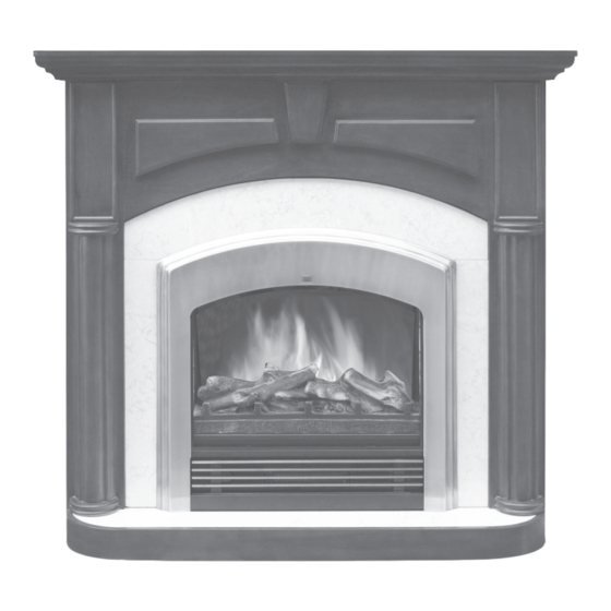
- Page 1 ELECTRIC FIREPLACE HEATER I N S T R U C T I O N M A N U A L QCM270-50D ATTENTION: 1. Find a location for the fireplace heater that is protected from direct sunlight. 2. Do not plug the electric fireplace heater into the power outlet before you read all instructions.
-
Page 2: Important Safety Instructions
S A F E T Y I N S T R U C T I O N S IMPORTANT SAFETY INSTRUCTIONS WHEN USING ELECTRICAL APPLIANCES, BASIC PRECAUTIONS SHOULD ALWAYS BE FOLLOWED TO REDUCE THE RISK OF FIRE, ELEC- TRIC SHOCK, AND INJURY TO PERSONS, INCLUDING THE FOLLOWING: 1) Read all instructions before using this 10) Connect to properly grounded outlets electric fireplace heater. - Page 3 S A F E T Y I N S T R U C T I O N S CAUTION This electric fireplace heater is for use on 120 volts. The cord has a plug as shown If you use this heater in conjunction with at A in Figure 1.
-
Page 4: Parts List
A S S E M B LY I N S T R U C T I O N S PARTS LIST: Fireplace insert A) Top panel B) Base panel C) Front Base D) Left Side panel E) Right Side panel F) Left Front panel G) Right Front panel H) Right Small panel... - Page 5 A S S E M B LY I N S T R U C T I O N S Step 3: Attach the LEFT SIDE PANEL (D) to the LEFT FRONT PANEL (F) with 3 KD SCREWS. Attach the RIGHT SIDE PANEL (E) to the RIGHT FRONT PANEL (G) with 3 KD SCREWS.
-
Page 6: Fireplace Insert Installation
A S S E M B LY I N S T R U C T I O N S fig. J fig. H Step 3: Once the INSERT is in place, attach Step 9: Tighten all SCREWS. See Fig. I MOUNTING BRACKET (V) to the bottom with 4 MED-KD SCREWS (W). -
Page 7: Operation
O P E R A T I O N Step 5: Move assembled unit to desired Once the fireplace heater has been properly location. Unit should not be positioned in an installed to the mantel, plug the fireplace area exposed to direct sunlight. into a 15AMP/120 Volt outlet. - Page 8 O P E R A T I O N indicator light will be on. The fireplace heater will give high heat level. Pressing once again will stop the high heat level function. May not be exactly as shown. OPERATION BY THE REMOTE CONTROL Plug in your electric fireplace and it will beep once, this means you have...
-
Page 9: Remote Control Battery Replacement
M A I N T E N A N C E adjust the temperature to your individual REPLACING THE requirements, turn the temperature con- FLAME EFFECT LIGHT AND trol dial to the right (clockwise) to increase LOG-SET LIGHT BULBS the desired temperature and to the left (counter clockwise) to lower the temperature. -
Page 10: Warranty
C L E A N I N G W A R R A N T Y CLEANING WARRANTY To clean unit first turn off controls on unit Every electric fireplace heater is tested and unplug the unit from power source. before it leaves the factory and it is To clean glass display panel;... -
Page 12: Foyer Électrique
FOYER ÉLECTRIQUE M A N U E L D ’ I N S T R U C T I O N S QCM270-50D ATTENTION : 1. Choisissez pour votre poêle-foyer électrique un emplacement protégé contre l’ensoleillement direct. 2. Ne branchez pas le poêle-foyer électrique dans la prise de... -
Page 13: Instructions De Sécurité Importantes
D I R E C T I V E S S É C U R I T É INSTRUCTIONS DE SÉCURITÉ IMPORTANTES POUR UTILISER UN APPAREIL ÉLECTRIQUE, VOUS DEVRIEZ TOUJOURS OBSERVER DES MESURES DE PRÉCAUTION DE BASE, AFIN DE RÉDUIRE LES RISQUES D’INCENDIES, DE DÉCHARGES ÉLECTRIQUES ET DE BLESSURES CORPORELLES, DONT LES SUIVANTES : 1) Lisez toutes les directives avant d’utiliser le les commandes en position hors circuit (OFF), puis... - Page 14 D I R E C T I V E S S É C U R I T E Le poêle-foyer électrique est conçu pour Ce foyer comporte une protection incorporée fonctionner sur un circuit de 120 V. Le contre les surchauffes. Si la protection cordon d’alimentation comporte une fiche, contre la surchauffe se déclenche, éteignez montrée dans l’illustration A ci-dessous.
-
Page 15: Directives D'assemblage
DIRECTIVES D’ASSEMBLAGE LISTE DES PIÈCES Inséré du foyer A) Panneau supérieur B) Panneau de base C) Socle avant D) Panneau latéraux gauche E) Panneau latéraux droit F) Panneau avant gauche G) Panneau avant droit H) Petit panneau droit I) Petit panneau gauche J) Panneau supérieur avant K) Panneau centre avant Q) Écrous K... - Page 16 DIRECTIVES D’ASSEMBLAGE Étape 3 : Fixer le panneau latéral gauche (D) au panneau avant gauche (F) à l’aide de 3 vis KD. Fixer le panneau latéral droit (E) au panneau avant droit (G) à l’aide de 3 vis KD. Voir diagramme C. fig.
- Page 17 DIRECTIVES D’ASSEMBLAGE Étape 8: Installez le PANNEAU SUPÉRIEUR [A] sur l’unité comme montré et fixez-le avec quatre VIS KD. Reportez-vous à la figure H fig. J fig. H Étape 3 : Une fois l’APPLIQUE en place, fixez quatre SUPPORTS DE MONTAGE (V) au bas avec quatre VIS KD MOYENNES (W).
- Page 18 F O N C T I O N N E M E N T Étape 5 : Déplacez l’unité montée à l’endroit 4. Utiliser la VIS DE MUR pour attacher souhaité. L ’unité ne doit pas être placée l’autre extrémité du CÂBLE DE SÉCURITÉ dans un endroit exposé...
- Page 19 F O N C T I O N N E M E N T Peut ne pas être exactement comme indiqué flammes. L ’unité émettra un signal sonore et le témoin lumineux s’allumera. Les ampoules simulant les flammes seront allumées. Presser à nouveau pour éteindre les ampoules.
-
Page 20: Entretien
E N T R E T I E N (W) d’ampoule recommandée. émettra un signal sonore et le témoin lumineux s’allumera. Les ampoules simulant les flammes seront allumées. Presser à nouveau pour étein- REMPLACEMENT DES dre les ampoules. AMPOULES D’EFFET DE FLAMME ET DE L ’ENSEMBLE 750 W : Appuyez sur ce bouton pour obtenir un niveau de chaleur faible. -
Page 21: Garantie
N E T T O Y A G E / G A R A N T I E GARANTIE NETTOYAGE Pour nettoyer l’appareil, mettre les Chaque poêle-foyer électrique est testé en commandes en position OFF, et le débrancher. usine et est garanti pour une période de un Pour nettoyer le panneau d’affichage en verre ;... - Page 23 CHIMENEA ELÉCTRICA — CALENTADOR M A N U A L D E I N S T R U C C I O N E S QCM270-50D IMPORTANTE: 1. Encuentre un lugar para instalar la chimenea eléctrica donde esté protegida de la luz solar directa.
-
Page 24: Medidas De Seguridad Importantes
M E D I D A S S E G U R I D A D MEDIDAS DE SEGURIDAD IMPORTANTES PARA REDUCIR EL RIESGO DE INCENDIO, DESCARGA ELÉCTRICA Y LESIONES PERSONALES AL UTILIZAR APARATOS ELÉCTRICOS, SIEMPRE SE DEBEN TOMAR CIERTAS PRECAUCIONES BÁSICAS, COMO LAS SIGUIENTES: 1) Lea todas las instrucciones antes de utilizar esta 10) Enchufe únicamente en un tomacorriente con chimenea eléctrica. - Page 25 M E D I D A S S E G U R I D A D Esta chimenea eléctrica debe utilizarse con La chimenea eléctrica está equipada con 120 voltios. El cable tiene un enchufe como se un protector contra el recalentamiento. observa en A en la figura 1.
-
Page 26: Montaje Del Gabinete
I N S T R U C C I O N E S D E M O N TA J E LISTADO DE PIEZAS: Dispositivo interno de la chimenea 1 A) Panel superior B) Panel inferior C) Base frontal D) Panel lateral izquierdo E) Panele lateral derecho F) Panel frontal izquierdo G) Panel frontal derecho... - Page 27 I N S T R U C C I O N E S D E M O N TA J E Paso 3: Acople el PANEL LATERAL DERECHO (D) al PANEL FRONTAL IZQUIERDO (F) con 3 tornillos KD. Acople el PANEL LATERAL IZQUIERDO (E) al PANEL FRONTAL DERECHO (G) con 3 TORNIL- LOS KD.
- Page 28 I N S T R U C C I O N E S D E M O N TA J E fig. J fig. H Paso 3: Ajuste todos los TORNILLOS KD.. Paso 3: Una vez que el INSERTO esté en su Consulte la Fig.
- Page 29 F U N C I O N A M I E N T O Paso 5: Mueva la unidad ensamblada a la 4. Use el TORNILLO PARA LA PARED para ubicación deseada. No deberá colocarla en sujetar el otro extremo del CABLE DE SEGU- un área con exposición directa al sol.
- Page 30 F U N C I O N A M I E N T O el botón para detener la función luminosa. 750W: Oprima este botón para la calefac- ción baja. La unidad emitirá un pitido. La luz del piloto y la luz indicadora se encenderán. El nivel de la calefacción de la chimenea –...
-
Page 31: Mantenimiento
M A N T E N I M I E N T O 750W: Oprima este botón para la calefacción baja. CAMBIO DE LAS BOMBILLAS La unidad emitirá un pitido. La luz del piloto y CON EFECTO DE LLAMAS la luz indicadora se encenderán. El nivel de la Y LEÑO calefacción de la chimenea –... - Page 32 L I M P I E Z A / G A R A N T Í A LIMPIEZA GARANTÍA Todas las chimeneas eléctricas se prueban Para limpiar la unidad, apague primero los controles y desenchúfela de la fuente de antes de salir de la fábrica y poseen garantía alimentación.
Need help?
Do you have a question about the QCM270-50D and is the answer not in the manual?
Questions and answers