
Related Manuals for Transpak TP-6000-1


Summary of Contents for Transpak TP-6000-1
- Page 1 AUTOMATIC POLYPROPYLENE STRAPPING MACHINE TP-6000-1 TP-6000-3 TP-6000CE1 TP-6000CE3 OPERATION MANUAL & SPARE PARTS LIST...
- Page 2 01/18/08 Explanations For Each Model No. : TP-6000-1 : Single Phase Model TP-6000-3 : Three Phase Model TP-6000CE1 : Single Phase With CE Version TP-6000CE3 : Three Phase With CE Version...
-
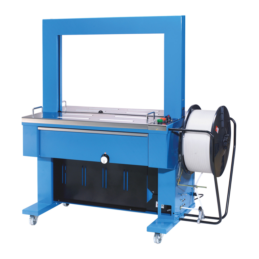
Page 3: Table Of Contents
01/18/08 PART I CONTENTS 1. Safety Instructions………..……..………………………. 2. Construction and Function of Units………..……..…….. 3. Technical Data …………………………..………………. 4. Control Panel …………………………..………………. Control Panel (CE Version) …………………………..… 5. Electric Control Unit …………………………..…………7~8 6. How to Load P.P. Strap ………………..……………….. 7. How to Operate …………..…………………………….. Recommend for Trouble-free Operation……..…………... -
Page 4: Safety Instructions
01/18/08 1. Safety Instructions (1) Before operating a. Please always wear proper eye protection and safety gloves before operating this machine. Eye protection must be worn Safety gloves must be worn b. Please make sure if the power voltage is correct. c. - Page 5 01/18/08 (5) Maintenance a. Please turn off the power before opening the top plate. b. Please do not touch the heater due to the high temperature. c. Be careful with the heater if you open the upper top plate. (6) Other remainders a.
-
Page 6: Strapping Head Unit
01/18/08 2. Construction and Function of Units 1 Strapping head unit This unit is the most important part of the machine for cutting and sealing of P.P. strap. 2 Bandway unit This is the arch track through which P.P. strap forwards or reverses. 5 Feed unit Feeding and reversing of strap. -
Page 7: Technical Data
01/18/08 3. Technical Data Sealing method Heat 8 mm to 12 mm (3/8"-1/2") Strap width: Strap thickness: 0.55 mm up to 0.75 mm (0.022" - 0.03") Strap reel diameter: 200 mm (8" nominal) Width : 1430 mm (56.3") Depth: 620 mm (24.4") Table height: 810 mm (31.9") Electrical connection:... -
Page 8: Control Panel
01/18/08 4. Control Panel a. (For Standard Version) 1 Start switch 5 Auto/Hand selector switch This is the switch to start a strapping While selector switch is placed to the position operation. A strapping cycle is "AUTO", the machine will automatically strap completed only after actuation of the package when it is placed on the table and this switch. - Page 9 01/18/08 b. (For CE Version) 1 Start switch This is the switch to start a strapping operation A strapping cycle is completed only after actuation of this switch. 3 F/R switch (Feed and Reverse) After P.P. strap is fed and the main power switch is on, turn this switch counterclockwise to feed P.P.
-
Page 10: Electric Control Unit
01/18/08 5. Electric Control Unit a. (For Three Phase) Magnetic switch 6 Timers 7 & 8 Timer , T1 7 : This is a current protection device. This Timer, T1, determines In case of overload, the over load relay the time necessary for strap take-up will cut off power automatically. - Page 11 01/18/08 b. (For Single Phase) Timers 30 & 29 Timer, T1 30 : This Timer, T1, determines the time necessary for strap take-up. Set Timer, T1, bearing in mind the time required for strapping the minimum-size package. Normally, Timer T1 is set at about 0.3 seconds, but may have to be adjusted depending on a package size.
-
Page 12: How To Load P.p. Strap
01/18/08 6. How to Load P.P. Strap . Ensure that the power supply switch is turned off before loading P.P. strap. Step 1 Place a strap coil on the reel drum according to the arrow direction as in- dicated on the Outer Flange 9 . After sliding on the coil, put the Outer Flange on the strap coil and tighten it using the Reel Nut Handle 10 . -
Page 13: How To Operate
01/18/08 7. How to Operate 8. Recommendations for Trouble-Free Operation For standard version : (1) Make sure to turn off the power supply Turn the power supply switch on. switch , when maintenance and/or exchange of strap coil is required. The pilot lamp lights up and the strap is automatically fed into the Accumulator Box. -
Page 14: Adjustments
01/18/08 9. Adjustments Tension strenght The tension knob is used to adjust the tension strenght for strapping. The range of strapping tension is 0-10, so that an operator can choose the adequate strapping tension for a package. Normal- ly, the knob position 4 or 5 is suitable for a carton box. - Page 15 01/18/08 Feed and take-up mechanism If this unit is not correctly adjusted, strap feed and take-up will become irregular. Normally, this unit is set to accept P.P. strap with the thicknesses of 0.55mm-0.6mm If a different strap thickness is used, adjust the section marked by a circle in the drawing so that the clearance between the Upper Roller Spring 23 and the Upper Shaft Spring Hook 24 should...
- Page 16 01/18/08 Limit switches ( Movements of control unit) LS3, 31 controls the machine to stop at home position and is adjusted by Limit Switch Contactor, 32 . When LS1 is activated, the control unit stops and the strap starts reversing. In the control unit, the right Press Unit 37 rises up to the top and grips the strap under Slide Table, 38 .
- Page 17 01/18/08 Amount of strap in Accumulator Box The machine has already been set in its Accumulator Box. However, some adjustment may be required, depending on the actual quality or thickness of the strap used. If adjustment is necessary, proceed as shown in the following drawing.
-
Page 18: Installation Of Arch
01/18/08 10. Installation of Arch Unit (1) Take the upper table 1 , 15 off. (2) Take the LH bandway 2 off. 6 TMS, M5x8 8 TMS, M6x8 11 HBS, M8x15 12 SW, M8 18 PW, M8 (A) (3) Slide the the arch unit 3 into the fixing brackets 4 and fix both sides of the arch frame with 11 12 18 . - Page 19 01/18/08...
- Page 20 01/18/08 11. Wiring Diagram a. TP-6000-1/TP-6000-1S -17-...
- Page 21 01/18/08 b. TP-6000CE1/TP-6000CE1S -18-...
- Page 22 01/18/08 c. TP-6000-3/TP-6000-3S/TP-6000CE3/TP-6000CE3S -19-...
- Page 23 01/18/08 d. TP-6000-3/TP-6000-3S -20-...
- Page 24 01/18/08 e. TP-6000CE3/TP-6000CE3S -21-...
- Page 25 01/18/08...
- Page 26 01/18/08 shape shape classification classification ∮ ∮ ∮ 8x 12~ 16x0.4~0.8t ∮ ∮ ∮ 6x 13~ 14x0.8~1.5t ∮ ∮ ∮ 8x 14~ 16x1.3~1.5t ∮ ∮ ∮ 6x 15~ 16x1.0~1.5t ∮ ∮ ∮ 8x 20~ 23x2.0t ∮ ∮ ∮ 6x 16~ 19x2.0t...
- Page 27 01/18/08 This bill of material, with the aid of illustrations, all the parts used in the TP-6000. When ordering, kindly submit a list using the descriptions, part no.s, and quantities as indicated. EXPLANATION OF BILL OF MATERIAL The following instructions are designed to assist you when ordering parts. 1.
- Page 28 01/18/08 PART II CONTENTS Strapping Head Unit ………………………………………… 1~30 2. Bandway Unit ………………………………………………31~37-4 3. Accumulator Unit ………………………………………… 38~44 4. Reel Unit …………………………………………………… 45~51 Body Frame Unit ……………………………………………52~61-2 6. Electric Control Unit……………………………………… 62~69-1...
- Page 29 01/18/08 STRAPPING HEAD UNIT T6-1-90000 T6-1-90012 T6-1-90013 REF. Q'TY PART NO. DESCRIPTION REMARKS T6-1-90000 Strapping Head Unit (For 12mm) T6-1-90012 Strapping Head Unit (For 9mm) T6-1-90013 Strapping Head Unit (For 15.5mm) T6-1-10006 Cam Group (For 1PH) SEE PAGE 2 T6-1-10007 Cam Group (For 3PH) T6-1-20005 Slide Table Group (For 12mm)
- Page 30 01/18/08 CAM GROUP T6-1-10006 T6-1-10007...
-
Page 31: Cam Shaft
01/18/08 CAM GROUP T6-1-10006 T6-1-10007 REF. PART NO. DESCRIPTION Q'TY REMARKS T6-1-10006 Cam Group (For 1PH) T6-1-10007 Cam Group (For 3PH) T6-1-10110 Tension Cam T6-1-10120 Cam Shaft End Plate T6-1-10130 Limit Cam (LS1) T6-1-10140 Limit Switch Contactor A (LS3) T6-1-10150 Limit Switch Contactor B (LS2) KYA070720 Key, 7x7x20... - Page 32 01/18/08 1-1-1 CAM ASS'Y T6-1-12000 REF. Q'TY PART NO. DESCRIPTION REMARKS T6-1-12110 Slide Table Cam T6-1-12120 RH Press Cam T6-1-12130 Center Press Cam T6-1-12140 Heater Cam T6-1-12150 LH Press Cam T6-1-12160 Cam Shaft T6-1-12170 Cam Shaft Coupling T6-1-12180 Collar, 28.8x34x28.3 T6-1-12190 Collar, 28.8x34x21 T6-1-12210...
- Page 33 01/18/08 SLIDE TABLE GROUP T6-1-20005...
- Page 34 01/18/08 SLIDE TABLE GROUP T6-1-20005 REF. PART NO. DESCRIPTION Q'TY REMARKS T6-1-20005 Slide Table Group (For 12mm) T6-1-20006 Slide Table Group (For 9mm) T6-1-20007 Slide Table Group (For 15.5mm) T6-1-20110 Slide Table Frame T6-1-20120 Slide Table Frame Shaft T6-1-20130 Slide Table (For 12mm) T6-1-20130S Slide Table (For 12mm)(Stainless Steel Model) T6-1-20133...
-
Page 35: Hbs, M6X20
01/18/08 SLIDE TABLE GROUP T6-1-20005 REF. PART NO. DESCRIPTION Q'TY REMARKS T6-1-20340 Bracket T6-1-20351 Spring T6-1-20360 Limit Switch T6-1-21000 Strap Guide Arm Ass'y SEE PAGE 7 T6-1-22000 Strap Guide Spring Ass'y SEE PAGE 8 HBS1050H HBS, M10x50 (H) HBS0830 HBS, M8x30 HBS0650H HBS, M6x50 (H) HBS0620N... - Page 36 01/18/08 1-2-1 STRAP GUIDE ARM ASS'Y T6-1-21000 REF. Q'TY PART NO. DESCRIPTION REMARKS T6-1-21110 Strap Guide Arm MB2025 Metal Bush, 2025...
- Page 37 01/18/08 1-2-2 STRAP GUIDE SPRING ASS'Y T6-1-22000 REF. Q'TY PART NO. DESCRIPTION REMARKS T6-1-22110 Strap Guide Spring T6-1-22120 Strap Guide Spring Bracket HBS0615 HBS, M6x15 HN06 HN, M6...
- Page 38 01/18/08 PRESS GROUP T6-1-30000...
- Page 39 01/18/08 PRESS GROUP T6-1-30000 REF. PART NO. DESCRIPTION Q'TY REMARKS T6-1-30110 Press Arm Shaft T6-1-30120 Cutter Tension Spring Hook T6-1-30130 Upper Roller Spring T6-1-30140 Upper Shaft Spring Adjuster T6-1-30150 Press Tension Spring T6-1-30160 Cutter Tension Spring T6-1-30170 Press Arm End Plate BR6304ZZ Bearing, 6304ZZ ER15...
- Page 40 01/18/08 RH, BLOCK ARM ASS'Y 1-3-1 T6-1-31000 REF. Q'TY PART NO. DESCRIPTION REMARKS T6-1-31110 RH, Block Arm T6-1-31120 Upper Cutter T6-1-31120S Upper Cutter (Stainless Steel Model) T6-1-31130 Upper Cutter Pin T6-1-31140 RH, Block Spring BR628ZZ Bearing, 628ZZ SP0824 Spring Pin, 8x24 HBS0835H HBS, M8x35 (H) HN10...
- Page 41 01/18/08 1-3-2 CENTER BLOCK ARM ASS'Y T6-1-32000 REF. Q'TY PART NO. DESCRIPTION REMARKS T6-1-32110 Center Block Arm T6-1-32120 Universal Press T6-1-32120S Universal Press (Stainless Steel Model) T6-1-32130 Lower Cutter T6-1-32130S Lower Cutter (Stainless Steel Model) T6-1-32140 Cutter Spring Hook T6-1-32150 LH &...
- Page 42 01/18/08 LH, BLOCK ARM ASS'Y 1-3-3 T6-1-33000 REF. Q'TY PART NO. DESCRIPTION REMARKS T6-1-33110 LH, Block Arm T6-1-33120 Jaw Left T6-1-32150 LH & Center Block Spring BR628ZZ Bearing, 628ZZ SP0820 Spring Pin, 8x20 SP0622 Spring Pin, 6x22 MB2020 Metal Bush, 2020 -13-...
- Page 43 01/18/08 HEATER GROUP T6-1-40000 -14-...
- Page 44 01/18/08 HEATER GROUP T6-1-40000 REF. PART NO. DESCRIPTION Q'TY REMARKS T6-1-40110 Heater Cover T6-1-40120 Heater Crank Spring T6-1-40130 Heater Slider Guide (L) T6-1-40140 Heater Slider Guide (R) T6-1-40150 Heater Crank Shaft ER15 Snap Ring, E-15 T6-1-40170 Heater Stopper LA-40002 Label T6-1-41000 Heater Ass'y T6-1-42000...
- Page 45 01/18/08 -16-...
- Page 46 01/18/08 1-4-2 HEATER CRANK ASS'Y T6-1-42000 REF. Q'TY PART NO. DESCRIPTION REMARKS T6-1-42110 Heater Crank T6-1-42120 Heater Bearing Shaft T6-1-42130 Heater Crank Collar BR6304ZZ Bearing, 6304ZZ MB2015 Metal Bush, 2015 ER15 Snap Ring, E-15 HN08 HN, M8 -17-...
- Page 47 01/18/08 STRAPPING HEAD GROUP T6-1-50000 -18-...
- Page 48 01/18/08 STRAPPING HEAD GROUP T6-1-50000 REF. PART NO. DESCRIPTION Q'TY REMARKS T6-1-50100 Strapping Head Frame T6-1-50111 Strap Width Block HBS0820 HBS, M8x20 HBS0620 HBS, M6x20 PW06B PW, M6 (B) SW08 SW, M8 PW08C PW, M8 (C) -19-...
- Page 49 01/18/08 TENSION GROUP T6-1-60000 -20-...
- Page 50 01/18/08 TENSION GROUP T6-1-60000 REF. PART NO. DESCRIPTION Q'TY REMARKS T6-1-60110 Tension Arm Shaft T6-1-60120 Tension Arm Spring T6-1-60130 Tension Adjusting Arm Spring T6-1-60140 Tension Arm Spacer T6-1-60150 Strap Cover T6-1-60160 Tension Arm Spring Hook L-Type BRHK2516 Bearing, HK2516 ER15 Snap Ring, E-15 BRIR202517 Bearing, IR202517...
- Page 51 01/18/08 1-6-1 TENSION ARM ASS'Y T6-1-61000 REF. Q'TY PART NO. DESCRIPTION REMARKS T6-1-61110 Tension Arm T6-1-61120 Tension Jaw Shaft T6-1-61130 Tension Arm Spring Hook I-Type T6-1-61140 Tension Jaw Spring T6-1-20250 Cam Follower, KR22xLL ER06 Snap Ring, E-6 HSS0810 HSS, M8x10 HN08 HN, M8 SW10...
- Page 52 01/18/08 1-6-3 T6-1-63000 REF. Q'TY PART NO. DESCRIPTION REMARKS T6-1-63110 Tension Adjusting Cam T6-1-63120 Tension Adjusting Shaft T6-1-63130 Plate (Tension Selector Knob) T6-1-63140 Tension Adjusting Cam Spring T6-1-63018 Tension Adjusting Cam Lock T6-1-63170 Tension ADJ Bolt Spacer T6-1-63180 Tension Indicated Arm HBS0620 HBS, M6x20 HBS0515...
- Page 53 01/18/08 1-6-3 TENSION ADJUSTING CAM ASS'Y T6-1-63001 REF. Q'TY PART NO. DESCRIPTION REMARKS T6-1-63011 Tension Adjusting Handle T6-1-63012 Tension Adjusting Shaft T6-1-63130 Plate (Tension Selector Knob) T6-1-63014 Tension Adjusting Cam T6-1-63015 Bush T6-1-63016 Support T6-1-63016S Support (Stainless Steel Model) T6-1-63017 Stopper T6-1-63018 Tension Adjusting Cam Lock...
- Page 54 01/18/08 1-6-3 TENSION ADJUSTING CAM ASS'Y T6-1-63001 REF. PART NO. DESCRIPTION Q'TY REMARKS NTE06 NTE, M6 HN05 HN, M5 SR12 Stop Ring, S-12 T6-1-63031 Bracket T6-1-63031S Bracket (Stainless Steel Model) TMS0508 TMS, M5x8 T6-1-63034 Washer SW06 SW, M6 HBS0610 HBS, M6x10 FMS0620S FMS, M6x20 (SUS) HN06...
- Page 55 01/18/08 1-6-4 TENSION ADJUSTING ASS'Y T6-1-64000 REF. Q'TY PART NO. DESCRIPTION REMARKS T6-1-64110 Tension Adjusting MB2015 Metal Bush, 2015 SP0645 Spring Pin, 6x45 -25-...
- Page 56 01/18/08 1-6-5 T6-1-65000 TENSION ADJUSTING ARM ASS'Y REF. Q'TY PART NO. DESCRIPTION REMARKS T6-1-65110 Tension Adjusting Arm T6-1-65120 Tension Adjusting Arm Spring Hook MB2015 Metal Bush, 2015 SP0645 Spring Pin, 6x45 -26-...
- Page 57 01/18/08 FEED GROUP T6-1-70010 T6-1-70011 T6-1-70012 REF. Q'TY PART NO. DESCRIPTION REMARKS T6-1-70010 Feed Group (For 12mm) T6-1-70011 Feed Group (For 9mm) T6-1-70012 Feed Group (For 15.5mm) T6-1-70110 V-Belt M-21 T6-1-71000 Feed Ass'y (For 12mm) SEE PAGE 28 T6-1-71004 Feed Ass'y (For 9mm) T6-1-71005 Feed Ass'y (For 15.5mm) T6-1-72000...
- Page 58 01/18/08 1-7-1 FEED ASS'Y T6-1-71000 -28-...
- Page 59 01/18/08 1-7-1 FEED ASS'Y T6-1-71000 REF. PART NO. DESCRIPTION Q'TY REMARKS T6-1-71000 Feed Ass'y (For 12mm) T6-1-71004 Feed Ass'y (For 9mm) T6-1-71005 Feed Ass'y (For 15.5mm) T6-1-71120 Upper Feed Roller (For 12mm) T6-1-71120S Upper Feed Roller (For 12mm) (Stainless Steel Model) T6-1-71121 Upper Feed Roller (For 9mm) T6-1-71121S...
- Page 60 01/18/08 1-7-1 FEED ASS'Y T6-1-71000 REF. PART NO. DESCRIPTION Q'TY REMARKS BR628ZZ Bearing, 628ZZ BR6202ZZ Bearing, 6202ZZ RR24 Snap Ring, H-24 RR35 Snap Ring, H-35 ER12 Snap Ring, E-12 HBS0645H HBS, M6x45 (H) HBS0645HS HBS, M6x45 (H)(Stainless Steel Model) HBS0615 HBS, M6x15 HSS0615 HSS, M6x15...
- Page 61 01/18/08 1-7-2 T6-1-72000 REF. Q'TY PART NO. DESCRIPTION REMARKS T6-1-72110 Upper Adjusting Base T6-1-72120 Upper Adjusting Spring Hook T6-1-72130 Upper Adjusting Spring Rod T6-1-72140 Spring HBS0512 HBS, M5x12 HN06 HN, M6 SW05 SW, M5 -30-...
- Page 62 01/18/08 BANDWAY UNIT T6-2-90008 REF. Q'TY PART NO. DESCRIPTION REMARKS T6-2-10000 Bandway Group (For 12mm) SEE PAGE 32 T6-2-10004 Bandway Group (For 9mm) T6-2-10010 Bandway Group (For 15.5mm) T6-2-20000 Chute Arch Group SEE PAGE 35 -31-...
- Page 63 01/18/08 BANDWAY GROUP T6-2-10000 -32-...
- Page 64 01/18/08 BANDWAY GROUP T6-2-10000 REF. PART NO. DESCRIPTION Q'TY REMARKS T6-2-10000 Bandway Group (For 12mm) T6-2-10004 Bandway Group (For 9mm) T6-2-10010 Bandway Group (For 15.5mm) T6-2-10100 RH Bandway Ass'y (Only 650W, 12mm) T6-2-10101 RH Bandway Ass'y (Only 650W, 9mm) T6-2-10102 RH Bandway Ass'y (Only 650W, 15.5mm) T6-2-11000 RH Bandway Ass'y (For 12mm)
- Page 65 01/18/08 BANDWAY GROUP T6-2-10000 REF. PART NO. DESCRIPTION Q'TY REMARKS T6-2-12080 LH Bandway Ass'y (For 2250W, 12mm /15.5mm) T6-2-12081 LH Bandway Ass'y (For 2250W, 9mm) T6-2-10670 Bracket (For 650W) TMS0608 TMS, M6x8 HBS0650 HBS, M6x50 TMS0508 TMS, M5x8 HN06 HN, M6 HN, M6 (Only 650W) PW06A PW, M6(A)
- Page 66 01/18/08 2-1-1 RH RANDWAY ASS'Y T6-2-11000 REF. Q'TY PART NO. DESCRIPTION REMARKS T6-2-11000 RH Bandway Ass'y (For 12mm) T6-2-11001 RH Bandway Ass'y (For 9mm) T6-2-11002 RH Bandway Ass'y (For 15.5mm) T6-2-11010 RH Bandway Ass'y (Only 650W, 12mm) T6-2-11011 RH Bandway Ass'y (Only 650W, 9mm) T6-2-11012 RH Bandway Ass'y (Only 650W, 15.5mm) T6-2-11110...
- Page 67 01/18/08 2-1-1 RH BANDWAY ASS'Y T6-2-11000 REF. PART NO. DESCRIPTION Q'TY REMARKS T6-2-11140 RH Bandway Flap Pin (Rear) RH Bandway Flap Pin (Rear) (Only 650W, 9mm) T6-2-11150 RH Bandway Flap Spring RH Bandway Flap Spring (Only 650W, 9mm) T6-2-11160 RH Bandway Flap Pin (Front) RH Bandway Flap Pin (Front) (Only 650W, 9mm) -33-1-...
- Page 68 01/18/08 LH BANDWAY ASS'Y 2-1-2 T6-2-12000 T6-2-12001 REF. Q'TY PART NO. DESCRIPTION REMARKS T6-2-12000 LH Bandway Ass'y (12mm/15.5mm) T6-2-12001 LH Bandway Ass'y (9mm) T6-2-12110 LH Bandway (For 850W, 12mm/15.5mm) T6-2-12200 LH Bandway (For 850W, 9mm) T6-2-12111 LH Bandway (For 650W, 12mm/15.5mm) T6-2-12201 LH Bandway (For 650W, 9mm) T6-2-12112...
- Page 69 01/18/08 2-1-2 LH BANDWAY ASS'Y T6-2-12000 T6-2-12001 REF. PART NO. DESCRIPTION Q'TY REMARKS T6-2-12120 LH Bandway Flap (For 850W, 12mm/15.5mm) T6-2-12210 LH Bandway Flap (For 850W, 9mm) T6-2-12121 LH Bandway Flap (For 650W, 12mm/15.5mm) T6-2-12211 LH Bandway Flap (For 650W, 9mm) T6-2-12122 LH Bandway Flap (For 1050W, 12mm/15.5mm) T6-2-12212...
- Page 70 01/18/08 CHUTE ARCH GROUP T6-2-20000 REF. Q'TY PART NO. DESCRIPTION REMARKS T6-2-21000 Arch Ass'y SEE PAGE 36 HBS0816 HBS, M8x16 HBS0816S HBS, M8x16 (Stainless Steel Model) PW08A PW, M8 (A) PW08AS PW, M8 (A) (Stainless Steel Model) SW08 SW, M8 SW08S SW, M8 (Stainless Steel Model) -35-...
- Page 71 01/18/08 2-2-1 ARCH ASS'Y T6-2-21000 -36-...
- Page 72 01/18/08 2-2-1 ARCH ASS'Y T6-2-21000 REF. PART NO. DESCRIPTION Q'TY REMARKS T6-2-20110 Arch Frame (For 850W x 600H) T6-2-20110S Arch Frame (Stainless Steel Model) (For 850W x 600H) T6-2-20120 Arch Bandway (For 850W x 600H) T6-2-20130 Arch Cover, Front (For 850W x 600H) T6-2-20130S Arch Cover, Front (Stainless Steel Model) (For 850W x 600H)
- Page 73 01/18/08 2-2-1 ARCH ASS'Y T6-2-21000 REF. PART NO. DESCRIPTION Q'TY REMARKS T6-2-20160 RH Side Guide Rail (For 600H) T6-2-20160S RH Side Guide Rail (Stainless Steel Model)(For 600H) T6-2-20161 RH Side Guide Rail (For 800H) T6-2-20161S RH Side Guide Rail (Stainless Steel Model)(For 800H) T6-2-20162 RH Side Guide Rail (For 1000H)
- Page 74 01/18/08 2-2-1 ARCH ASS'Y T6-2-21000 REF. PART NO. DESCRIPTION Q'TY REMARKS T6-2-20180 Corner Guide Rail, Upper T6-2-20180S Corner Guide Rail, Upper (Stainless Steel Model) T6-2-20190 Corner Guide Rail, Lower (LH) T6-2-20190S Corner Guide Rail, Lower (LH) (Stainless Steel Model) T6-2-20200 Corner Guide Rail, Lower (RH) T6-2-20200S Corner Guide Rail, Lower (RH)
- Page 75 01/18/08 2-2-1 ARCH ASS'Y T6-2-21000 REF. PART NO. DESCRIPTION Q'TY REMARKS T6-2-20344 Back Guide Plate, Upper (For 1650W) T6-2-20344S Back Guide Plate, Upper (Stainless Steel Model)(For 1650W) T6-2-20345 Back Guide Plate, Upper (For 1850W) T6-2-20345S Back Guide Plate, Upper (Stainless Steel Model)(For 1850W) T6-2-20346 Back Guide Plate, Upper (For 2050W) T6-2-20346S...
- Page 76 01/18/08 2-2-1 ARCH ASS'Y T6-2-21000 REF. PART NO. DESCRIPTION Q'TY REMARKS T6-2-21370 Back Guide Plate, LH Lower T6-2-21370S Back Guide Plate, LH Lower (Stainless Steel Model) T6-2-21380 Back Guide Plate, RH Lower T6-2-21380S Back Guide Plate, RH Lower (Stainless Steel Model) PN, ∮4 (For 850Wx600H) PN04 PN, ∮4 (Stainless Steel Model)
-
Page 77: Accumulator Unit
01/18/08 ACCUMULATOR UNIT T6-3-90004 REF. Q'TY PART NO. DESCRIPTION REMARKS T6-3-90004 Accumulator Unit (For 12mm) T6-3-90005 Accumulator Unit (For 15.5mm) T6-3-90008 Accumulator Unit (For 9mm) T6-3-10000 Accumulator Group (For 12mm) SEE PAGE 39 T6-3-10003 Accumulator Group (For 9mm) T6-3-10004 Accumulator Group (For 15.5mm) SEE PAGE 43 T6-3-20000 Accumulator Box Group (For 12mm) - Page 78 01/18/08 ACCUMULATOR GROUP T6-3-10000 -39-...
- Page 79 01/18/08 ACCUMULATOR GROUP T6-3-10000 REF. PART NO. DESCRIPTION Q'TY REMARKS T6-3-10000 Accumulator Group (For 12mm) T6-3-10003 Accumulator Group (For 9mm) T6-3-10004 Accumulator Group (For 15.5mm) T6-3-10110 Balance Bar (For 12mm) T6-3-10111 Balance Bar (For 9mm) T6-3-10112 Balance Bar (For 15.5mm) T6-3-10120 Accumulator Balance Spring T6-3-10130...
- Page 80 01/18/08 ACCUMULATOR GROUP T6-3-10000 REF. PART NO. DESCRIPTION Q'TY REMARKS SW08 SW, M8 SW06 SW, M6 SW06S SW, M6 (Stainless Steel Model) T6-3-10321 Cover PW05 PW, M5 SW05 SW, M5 HBS0510 HBS, M5x10 -40-1-...
- Page 81 01/18/08 3-1-1 ACCUMULATOR ASS'Y T6-3-11000 -41-...
- Page 82 01/18/08 3-1-1 T6-3-11000 ACCUMULATOR ASS'Y REF. PART NO. DESCRIPTION Q'TY REMARKS T6-3-11000 Accumulator Ass'y (For 12mm) T6-3-11001 Accumulator Ass'y (For 9mm) T6-3-11002 Accumulator Ass'y (For 15.5mm) T6-3-11110 Accumulator Bearing Case T6-3-11120 Accumulator Lower Shaft T6-3-11130 Accumulator Lower Roller T6-3-11140 Accumulator Main Roller & Shaft T6-3-11150 Accumulator Balance Bar Holder T6-3-11160...
- Page 83 01/18/08 ACCUMULATOR BOX GROUP T6-3-20000 -43-...
- Page 84 01/18/08 ACCUMULATOR BOX GROUP T6-3-20000 REF. PART NO. DESCRIPTION Q'TY REMARKS T6-3-20000 Accumulator Box Group (For 12mm) T6-3-20003 Accumulator Box Group (For 9mm) T6-3-20004 Accumulator Box Group (For 15.5mm) T6-3-20120 Accumulator Box Front, RH T6-3-20120S Accumulator Box Front, RH (Stainless Steel Model) T6-3-20130 Accumulator Box Front, LH T6-3-20130S...
- Page 85 01/18/08 ACCUMULATOR BOX GROUP T6-3-20000 REF. PART NO. DESCRIPTION Q'TY REMARKS SW04 SW, M4 SW04S SW, M4 (Stainless Steel Model) SW05 SW, M5 SW05S SW, M5 (Stainless Steel Model) -44-1-...
-
Page 86: Reel Unit
01/18/08 REEL UNIT T6-4-90000 REF. Q'TY PART NO. DESCRIPTION REMARKS T6-4-10000 Reel Guard Group SEE PAGE 46 T6-4-20000 Reel Control Group SEE PAGE 48 T6-4-20000S Reel Control Group (Stainless Steel Model) SEE PAGE 48 -45-... - Page 87 01/18/08 REEL GUARD GROUP T6-4-10000 REF. Q'TY PART NO. DESCRIPTION REMARKS T6-4-11000 Free Angle Bracket Holder Ass'y SEE PAGE 47 T6-4-10530 Reel Guard (Front) T6-4-10530S Reel Guard (Front) (Stainless Steel Model) T6-4-10540 Reel Guard (Rear) T6-4-10540S Reel Guard (Rear) (Stainless Steel Model) HBS1020 HBS, M10x20 HBS1020S...
- Page 88 01/18/08 4-1-1 FREE ANGLE BRACKET T6-4-11000 HOLDER ASS'Y REF. Q'TY PART NO. DESCRIPTION REMARKS T6-4-11110 Free Angle Bracket Holder T6-4-11120 Free Angle Roller Bracket T6-4-11130 Strap Guide Roller ∮ T6-4-11140 Rivet, 6x30 ∮ PN06 HSS0610 HSS, M6x10 HSS0610S HSS, M6x10 (Stainless Steel Model) -47-...
- Page 89 01/18/08 REEL CONTROL GROUP T6-4-20000 T6-4-20000S -48-...
- Page 90 01/18/08 REEL CONTROL GROUP T6-4-20000 T6-4-20000S REF. PART NO. DESCRIPTION Q'TY REMARKS T6-4-20000 Reel Control Group T6-4-20000S Reel Control Group (Stainless Steel Model) T6-4-20110 Reel Unit Base T6-4-20130 Brake Tension Holder T6-4-20140 Brake Belt Tightener T6-4-20140S Brake Belt Tightener (Stainless Steel Model) T6-4-20150 Reel Shaft T6-4-20150S...
- Page 91 01/18/08 REEL CONTROL GROUP T6-4-20000 T6-4-20000S REF. PART NO. DESCRIPTION Q'TY REMARKS TC-021 Split Pin TC-075 Center Drum 280mm (Option) T6-4-21000 Brake Belt Ass'y SEE PAGE 50 T6-4-22000 Free Slide Roller Ass'y SEE PAGE 51 HBS0625 HBS, M6x25 HBS0625S HBS, M6x25 (Stainless Steel Model) HBS0620 HBS, M6x20 HBS0620S...
- Page 92 01/18/08 4-2-1 BRAKE BELT ASS'Y T6-4-21000 REF. Q'TY PART NO. DESCRIPTION REMARKS T6-4-21110 Brake Belt Holder T6-4-21120 Brake Holder Plate T6-4-21130 Brake V-Belt PMS0420 PMS, M4x20 SW04 SW, M4 HN04 HN, M4 -50-...
- Page 93 01/18/08 4-2-2 FREE SLIDE ROLLER ASS'Y T6-4-22000 REF. Q'TY PART NO. DESCRIPTION REMARKS T6-4-22110 Free Slide Roller Bracket T6-4-22110S Free Slide Roller Bracket (Stainless Steel Model) TE-028 Roller ∮ T6-4-11140 Rivet, 6x30 ∮ T6-4-11140S Rivet, 6x30 (Stainless Steel Model) ∮ PN06 ∮...
- Page 94 01/18/08 BODY FRAME UNIT T6-5-90004 REF. Q'TY PART NO. DESCRIPTION REMARKS Body Frame Group T6-5-10014 SEE PAGE 53 Body Frame Group (Stainless Steel T6-5-10014S Model) -52-...
- Page 95 01/18/08 BODY FRAME GROUP T6-5-10014 -53-...
- Page 96 01/18/08 BODY FRAME GROUP T6-5-10014 REF. PART NO. DESCRIPTION Q'TY REMARKS T6-5-10047 Front Door (For Non CE Only) T6-5-10047S Front Door (Stainless Steel Model) (For Non CE Only) T6-5-10127 Front Door (For Non CE Only, Outside Tension) T6-5-10127S Front Door (Stainless Steel Model) (For Non CE Only, Outside Tension) T6-5-10122 Front Door (For CE)
- Page 97 01/18/08 BODY FRAME GROUP T6-5-10014 REF. PART NO. DESCRIPTION Q'TY REMARKS T6-5-11000 Upper Table, Front Set (For 850W) SEE PAGE 56 T6-5-11000S Upper Table, Front Set SEE PAGE 56 (Stainless Steel Model)(For 850W) T6-5-11009 Upper Table, Front Set (For 650W) T6-5-11009S Upper Table, Front Set (Stainless Steel Model)(For 650W)
- Page 98 01/18/08 BODY FRAME GROUP T6-5-10014 REF. PART NO. DESCRIPTION Q'TY REMARKS T6-5-10590 Upper Left Table, Rear Set (For 1050W) SEE PAGE 61 T6-5-10600 Upper Left Table, Rear Set (For 1250W) T6-5-10850 Upper Left Table, Rear Set (For 1450W) T6-5-10851 Upper Left Table, Rear Set (For 1650W) T6-5-10852 Upper Left Table, Rear Set (For 1850W) T6-5-10853...
- Page 99 01/18/08 UPPER TABLE, FRONT SET 5-1-1 T6-5-11000 T6-5-11009 REF. Q'TY PART NO. DESCRIPTION REMARKS T6-5-11000 Upper Table, Front Set (For 850W) T6-5-11009 Upper Table, Front Set (For 650W) T6-5-11110 Upper Table Front (For 850W) T6-5-11110S Upper Table Front (Stainless Steel Model) (For 850W) T6-5-11010 Upper Table Front (For 650W)
- Page 100 01/18/08 UPPER TABLE, REAR SET 5-1-2 T6-5-12000 T6-5-12009 REF. Q'TY PART NO. DESCRIPTION REMARKS T6-5-12000 Upper Table, Rear Set (For 850W) T6-5-12009 Upper Table, Rear Set (For 650W) T6-5-12110 Upper Rear (For 850W) T6-5-12110S Upper Rear (Stainless Steel Model) (For 850W) T6-5-12010 Upper Rear (For 650W) T6-5-12010S...
- Page 101 01/18/08 5-1-3 T6-5-10540 REF. Q'TY PART NO. DESCRIPTION REMARKS T6-5-11020 Upper Right Table Front (For 1050~2250W) T6-5-11020S Upper Right Table Front (Stainless Steel Model)(For 1050~2250W) T6-5-11120 Table Roller T6-5-11121 Table Roller (Stainless Steel Model) T6-5-11130 Table Roller Shaft T6-5-11131 Table Roller Shaft (Stainless Steel Model) ER07 Snap Ring, E-7 ER07S...
- Page 102 01/18/08 5-1-4 T6-5-10582 REF. Q'TY PART NO. DESCRIPTION REMARKS T6-5-12022 Upper Right Rear (For 1050~2250W) T6-5-12022S Upper Right Rear (Stainless Steel Model) (For 1050~2250W) T6-5-11120 Table Roller T6-5-11121 Table Roller (Stainless Steel Model) T6-5-11130 Table Roller Shaft T6-5-11131 Table Roller Shaft (Stainless Steel Model) ER07 Snap Ring, E-7 ER07S...
- Page 103 01/18/08 5-1-5 T6-5-10550 REF. Q'TY PART NO. DESCRIPTION REMARKS T6-5-10550 Upper Left Table, Front Set (For 1050W) T6-5-10560 Upper Left Table, Front Set (For 1250W) T6-5-10570 Upper Left Table, Front Set (For 1450W) T6-5-10571 Upper Left Table, Front Set (For 1650W) T6-5-10572 Upper Left Table, Front Set (For 1850W) T6-5-10573...
- Page 104 01/18/08 UPPER LEFT TABLE, FRONT SET 5-1-5 T6-5-10550 REF. PART NO. DESCRIPTION Q'TY REMARKS T6-5-11080 Upper Left Table Front (For 2050W) T6-5-11080S Upper Left Table Front (Stainless Steel Model)(For 2050W) T6-5-11090 Upper Left Table Front (For 2250W) T6-5-11090S Upper Left Table Front (Stainless Steel Model)(For 2250W) T6-5-11120 Table Roller (For 1050W~1450W)
- Page 105 01/18/08 UPPER LEFT TABLE, FRONT SET 5-1-5 T6-5-10550 REF. PART NO. DESCRIPTION Q'TY REMARKS TMS0612 TMS, M6x12 TMS0612S TMS, M6x12 (Stainless Steel Model) SW06 SW, M6 SW06S SW, M6 (Stainless Steel Model) -60-2-...
- Page 106 01/18/08 5-1-6 UPPER LEFT TABLE, REAR SET T6-5-10590 REF. Q'TY PART NO. DESCRIPTION REMARKS T6-5-10590 Upper Left Table, Rear Set (For 1050W) T6-5-10600 Upper Left Table, Rear Set (For 1250W) T6-5-10850 Upper Left Table, Rear Set (For 1450W) T6-5-10851 Upper Left Table, Rear Set (For 1650W) T6-5-10852 Upper Left Table, Rear Set (For 1850W) T6-5-10853...
- Page 107 01/18/08 UPPER LEFT TABLE, REAR SET 5-1-6 T6-5-10590 REF. PART NO. DESCRIPTION Q'TY REMARKS T6-5-12080 Upper Left Table Rear (For 2050W) T6-5-12080S Upper Left Table Rear (Stainless Steel Model)(For 2050W) T6-5-12090 Upper Left Table Rear (For 2250W) T6-5-12090S Upper Left Table Rear (Stainless Steel Model)(For 2250W) T6-5-11120 Table Roller (For 1050W~1450W)
- Page 108 01/18/08 UPPER LEFT TABLE, REAR SET 5-1-6 T6-5-10590 REF. PART NO. DESCRIPTION Q'TY REMARKS TMS0612 TMS, M6x12 TMS0612S TMS, M6x12 (Stainless Steel Model) SW06 SW, M6 SW06S SW, M6 (Stainless Steel Model) -61-2-...
- Page 109 T6-6-10026 Electric Control Group (For 220V/3PH) T6-6-10027 Electric Control Group (For 380V/3PH) T6-6-10028 Electric Control Group (For 415V/3PH) T6-6-30024 Electric Box Group (For TP-6000-1) SEE PAGE 66 T6-6-40027 Electric Box Group (For TP-6000CE1) T6-6-50001 Electric Box Group (For TP-6000-3) T6-6-50002...
- Page 110 01/18/08 ELECTRIC CONTROL GROUP T6-6-10030 -63-...
- Page 111 01/18/08 ELECTRIC CONTROL GROUP T6-6-10030 REF. PART NO. DESCRIPTION Q'TY REMARKS T6-6-10030 Electric Control Group (For 220V/1PH) T6-6-10008 Electric Control Group (For 100V/1PH) T6-6-10009 Electric Control Group (For 110V/1PH) T6-6-10019 Electric Control Group (For 240V/1PH) T6-6-10026 Electric Control Group (For 220V/3PH) T6-6-10027 Electric Control Group (For 380V/3PH) T6-6-10028...
- Page 112 01/18/08 ELECTRIC CONTROL GROUP T6-6-10030 REF. PART NO. DESCRIPTION Q'TY REMARKS T6-6-40006 Transformer Box T6-6-40006S Transformer Box (Stainless Steel Model) T6-6-10320 Heater Terminal T6-6-10340 Cable Gland (PG13.5) T6-6-10350 Foot Switch Consent T6-6-10360 Limit Switch (LS1-3) T6-6-10370 Limit Switch Cover (LS1-3) T6-6-10380 Limit Switch (LS4) TF-027...
- Page 113 01/18/08 ELECTRIC CONTROL GROUP T6-6-10030 REF. PART NO. DESCRIPTION Q'TY REMARKS T6-6-30080 Motor (M3) (For 220V/1PH) T6-6-30056 Motor (M3) (For 100V/1PH) T6-6-30057 Motor (M3) (For 110V/1PH) T6-6-30058 Motor (M3) (For 240V/1PH) T6-6-10442 Motor (M3) (For 220V/3PH) T6-6-10444 Motor (M3) (For 380V/3PH) T6-6-10445 Motor (M3) (For 415V/3PH) T6-6-30200...
- Page 114 01/18/08 ELECTRIC CONTROL GROUP T6-6-10030 REF. PART NO. DESCRIPTION Q'TY REMARKS PW06D PW, M6 (D)(For 1PH) PW06C PW, M6 (C)(For 1PH) PW, M6 (C)(For 3PH) TF-006 Micro Switch (Option) PW05 PW, M5 PW04 PW, M4 SW05 SW, M5 SW06 SW, M6 T6-6-10172 Heater Transformer Ass'y (For 110V) T6-6-10171...
- Page 115 01/18/08 ELECTRIC CONTROL GROUP T6-6-10030 REF. PART NO. DESCRIPTION Q'TY REMARKS T6-6-10980 Cable Gland (PG11) T6-6-30135 Lamp FTP0416A FTP, 4x16 (A) -65-3-...
- Page 116 01/18/08 ELECTRIC CONTROL GROUP T6-6-30024 T6-6-40027 TP-6000-1/TP-6000CE1 -66-...
- Page 117 01/18/08 ELECTRIC CONTROL GROUP T6-6-30024 T6-6-40027 REF. PART NO. DESCRIPTION Q'TY REMARKS T6-6-30024 Electric Control Group (For 1PH, Non CE) T6-6-40027 Electric Control Group (For 1PH, CE) T6-6-30013 Connector (LS1.2.3.) T6-6-30014 Connector (Switch 2) T6-6-30015 Connector (Switch 1) T6-6-30016 Connector (LS4/Foot) T6-6-30017 Connector (Braker) T6-6-30018...
- Page 118 01/18/08 ELECTRIC CONTROL GROUP T6-6-30024 T6-6-40027 REF. PART NO. DESCRIPTION Q'TY REMARKS TMS0508 TMS, M5x8 T6-6-30047 EMI Filter T6-6-30049 Variable Resistor (1M) TMS0412 TMS, M4x12 (For CE) SW04 SW, M4 (For CE) HN04 HN, M4 (For CE) -67-1-...
- Page 119 01/18/08 ELECTRIC CONTROL GROUP T6-6-50001 T6-6-50002 TP-6000-3/TP-6000CE3 -68-...
- Page 120 01/18/08 ELECTRIC CONTROL GROUP T6-6-50001 T6-6-50002 REF. PART NO. DESCRIPTION Q'TY REMARKS T6-6-50001 Electric Control Group (For 3PH, Non CE) T6-6-50002 Electric Control Group (For 3PH, CE) T6-6-50110 Electric Box T6-6-50130 Panel T6-6-50140 Terminal (Ground) T6-6-50150 Terminal (Control)(Single in, single out) T6-6-50160 Magnetic Switch T6-6-50170...
- Page 121 01/18/08 ELECTRIC CONTROL GROUP T6-6-50001 T6-6-50002 REF. PART NO. DESCRIPTION Q'TY REMARKS TMS0508 TMS, M5x8 T5-2-10500 Cable Gland (PG9) T6-6-10980 Cable Gland (PG11) T6-6-10340 Cable Gland (PG13.5) SW06 SW, M6 HN06 HN, M6 T6-6-50410 End Plate (Control) 01/2008 -69-1-...
Need help?
Do you have a question about the TP-6000-1 and is the answer not in the manual?
Questions and answers