Advertisement
Quick Links
Harbor Breeze® is a registered trademark
of LF, LLC. All Rights Reserved.
ATTACH YOUR RECEIPT HERELISTED FOR WET LOCATION
Serial Number _________________________
Questions, problems, missing parts? Before returning to your retailer, call our customer
service department at 1-800-643-0067, 8 a.m. - 6 p.m., EST, Monday - Thursday, 8 a.m. - 5
p.m., EST, Friday.
EB13354
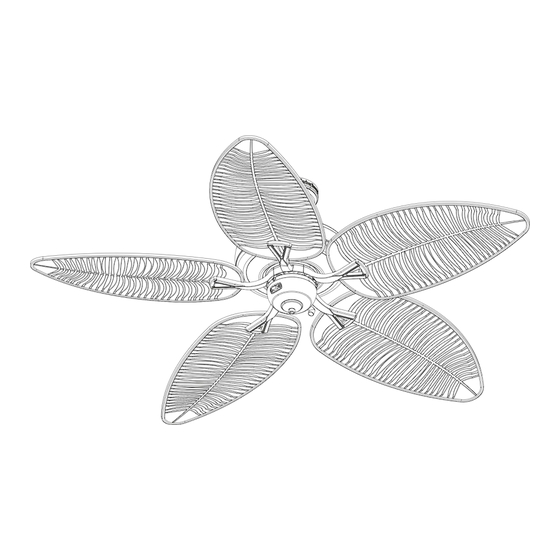
PACIFIC GROVE
Purchase Date _________________________
Lowes.com/harborbreeze
1
ITEM #0451809
CEILING FAN
MODEL #40101
Español p.
23
Advertisement

Subscribe to Our Youtube Channel
Related Manuals for Harbor Breeze 40101


Summary of Contents for Harbor Breeze 40101
-
Page 1: Ceiling Fan
ITEM #0451809 PACIFIC GROVE CEILING FAN MODEL #40101 Harbor Breeze® is a registered trademark Español p. of LF, LLC. All Rights Reserved. ATTACH YOUR RECEIPT HERELISTED FOR WET LOCATION Serial Number _________________________ Purchase Date _________________________ Questions, problems, missing parts? Before returning to your retailer, call our customer service department at 1-800-643-0067, 8 a.m. -
Page 2: Table Of Contents
TABLE OF CONTENTS Package Contents ..............Hardware Contents . - Page 3 PART DESCRIPTION QUANTITY Downrod Canopy (preassembled to Mounting Bracket (C)) Mounting Bracket Yoke Cover Motor Assembly Blade Switch Housing Blade Arm Fitter Plate Canopy Cover (preassembled to Canopy (B)) Switch Housing Plate (preassembled to the Motor Assembly (E)) Lowes.com/harborbreeze...
- Page 4 HARDWARE CONTENTS Motor Screw Wire Pull Chain Downrod Clip Downrod Pin Qty. 10 Connector Extension Qty. 1 Qty. 1 (preassembled to Qty. 3 + 1 extra Qty. 1 (preassembled to (preassembled to Motor Assembly (E)) Downrod (A)) Downrod (A)) + 1 extra Motor Housing Set Closemount Mounting Bracket...
- Page 5 Motor Motor Mounting Bracket Assembly (E)) Assembly (E)) (C)) Spring Washer Rubber Washer Switch Housing Switch Housing Qty. 10 Qty. 15 + 1 extra Plate Screw Screw (preassembled to Qty. 3 Qty. 3 Motor Screw (AA)) (preassembled to (preassembled to + 1 extra Switch Housing the Fitter Plate (I))
- Page 6 SAFETY INFORMATION Please read and understand this entire manual before attempting to assemble, operate or install the product. • Before you begin installing the fan, disconnect the power by removing fuses or turning off the circuit breakers. • Make sure that all electrical connections comply with local codes, ordinances, the National Electrical Code, and ANSI/NFPA 70-199.
-
Page 7: Preparation
WARNING: To reduce risk fire electric shock, do with solid-state speed-control device or control the fan speed with a full-range dimmer switch. WARNING: To reduce risk fire, electric shock, or personal injury, do bend the blade arms when installing them, balancing the blades, or cleaning the fan. - Page 8 1. Turn off the circuit breakers and the wall switch to the fan supply line leads. DANGER: Failure to disconnect the power supply prior to installation may result in serious injury or death. 2. Determine the mounting method to use. Note: Flushmount installation is not available...
- Page 9 3. Ensure the blades (F) will be at least 30 in. from any obstructions. Also check the downrod (A) length to ensure the blades (F) will be at least 7 ft. above floor. Lowes.com/harborbreeze...
- Page 10 INITIAL INSTALLATION 4. Remove the two mounting bracket screws (HH) from the round holes of canopy (B). Set aside for later use. Detach mounting bracket (C) from canopy (B). Mounting Bracket Screw Hardware Used 5. Feed black, blue and white wires from the plug on the mounting bracket (C) up through the hole in the top.
-
Page 11: Standard Or Angle Mounting Instructions
STANDARD OR ANGLE MOUNTING INSTRUCTIONS gauges and there is more than one house wire to connect to the two fan lead wires, consult an electrician for the proper size wire connectors to use. CAUTION: Be sure the outlet box (not included) is properly grounded or that a ground (green or bare) wire is present. - Page 12 STANDARD OR ANGLE MOUNTING INSTRUCTIONS Note: The Black wire is hot power for the fan. The White wire is common. The Blue wire is hot power for light (sold separately; wiring instructions will differ if optional light kit is purchased. Refer to light kit manufacturer’s instructions).
- Page 13 STANDARD OR ANGLE MOUNTING INSTRUCTIONS Lowes.com/harborbreeze...
- Page 14 STANDARD OR ANGLE MOUNTING INSTRUCTIONS 7. Insert the downrod (A) into the yoke of the motor assembly (E), align the holes, and re-install the downrod clip (DD) and downrod pin (EE). Secure the motor housing set screws (FF) and slide the yoke cover (D) down until it rests on top of the motor assembly (E).
-
Page 15: Closemount Instructions
CLOSEMOUNT INSTRUCTIONS Turn the spliced/taped wires upward and gently push the wires and wire connector (BB) into the outlet box. Proceed to FINAL INSTALLATION on page 15. Hardware Used WARNING: reduce risk fire, electrical shock, or personal injury, wire connectors provided with this fan are designed to accept only one 12-gauge house wire and two lead wires from the fan. - Page 16 CLOSEMOUNT INSTRUCTIONS Note: The Black wire is hot power for the fan. The White wire is common. The Blue wire is hot power for light (sold separately; wiring instructions will differ if optional light kit is purchased. Refer to light kit manufacturer’s instructions). Wiring instructions will differ if optional light kit is purchased.
- Page 17 CLOSEMOUNT INSTRUCTIONS (A) and canopy cover (J) are not used in this type of installation. Raise the fan and place the canopy (B) on the hook on the mounting bracket (C). Lowes.com/harborbreeze...
-
Page 18: Final Installation
FINAL INSTALLATION Note: Downrod (A) is shown/referenced, but instructions are applicable to both standard and closemount-style installations. 1. Wrap the wire harness coming from the downrod (A) around the hooks on the back of the mounting bracket (C). Note: Extra wire harness length accommodates longer downrods (sold separately). - Page 19 FINAL INSTALLATION 3. Align the key slots on the canopy (B) with the heads of the mounting bracket screws (HH) preassembled on mounting bracket (C). Lift the canopy (B) up and rotate it clockwise until the mounting bracket screws (HH) engage the key slots.
- Page 20 FINAL INSTALLATION Hardware Used Lowes.com/harborbreeze...
- Page 21 FINAL INSTALLATION Lowes.com/harborbreeze...
- Page 22 FINAL INSTALLATION Lowes.com/harborbreeze...
- Page 23 FINAL INSTALLATION Lowes.com/harborbreeze...
- Page 24 FINAL INSTALLATION Lowes.com/harborbreeze...
-
Page 25: Care And Maintenance
CARE AND MAINTENANCE At least twice each year, lower the canopy to check the downrod assembly, and then tighten all screws on the fan. Clean the motor housing with only a soft brush or lint-free cloth to avoid scratching finish. Clean the blades with lint-free cloth. - Page 26 1. The blades are loose. 1. Check and tighten all screws that hold the fan blades to the blade arms and the motor. 2. Replace the cracked blade. 2. There is a cracked blade. 3. Do not use a full range dimmer 3.
- Page 27 1. The blades and/or blade are 1. Check and tighten all screws that loose. hold the fan blades to the blade arms and the blade arms to the motor. 2. The blades are unbalanced. 2. Switch one blade with a blade from the opposite side.
- Page 28 LIFETIME LIMITED WARRANTY The manufacturer warrants this fan to be free from defects in workmanship and materials present at time of shipment from the factory for a lifetime from the date of purchase by the original purchaser. The retailer also warrants that all other fan parts, excluding any glass or plexiglas blades, to be free from defects in workmanship and material at the time of shipment from the factory for a period of one year after the date of purchase by the original purchaser.
- Page 29 REPLACEMENT PARTS LIST For replacement parts, call the customer service department at 1-800-643-0067, 8 a.m. - 6 p.m., EST, Monday - Thursday, 8 a.m. - 5 p.m., EST, Friday. PART DESCRIPTION PART # Downrod 0451809-A Canopy 0451809-B Mounting Bracket 0451809-C Blade Arm 0451809-H Blade...
Need help?
Do you have a question about the 40101 and is the answer not in the manual?
Questions and answers