
Related Manuals for Tektronix TLA5204


Summary of Contents for Tektronix TLA5204
- Page 1 Tektronix TLA5204 Manual Get Pricing & Availability at ApexWaves.com Call Today: 1-800-915-6216 Email: sales@apexwaves.com https://www.apexwaves.com/analyzers/tektronix-inc/tla5000/TLA5204...
-
Page 2: Service Manual
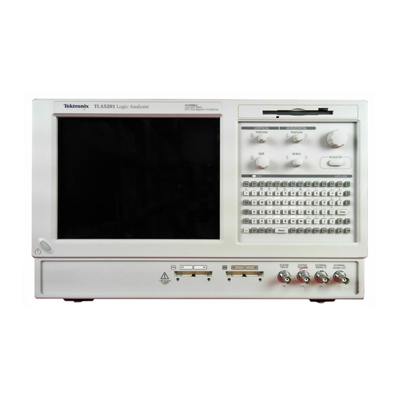
Service Manual TLA5000 Series Tektronix Logic Analyzer 071-1305-00 This document applies to firmware version 1.00 and above. Warning The servicing instructions are for use by qualified personnel only. To avoid personal injury, do not perform any servicing unless you are qualified to do so. - Page 3 Copyright © Tektronix, Inc. All rights reserved. Tektronix products are covered by U.S. and foreign patents, issued and pending. Information in this publication supercedes that in all previously published material. Specifications and price change privileges reserved. Tektronix, Inc., P.O. Box 500, Beaverton, OR 97077...
- Page 4 Tektronix, with shipping charges prepaid. Tektronix shall pay for the return of the product to Customer if the shipment is to a location within the country in which the Tektronix service center is located. Customer shall be responsible for paying all shipping charges, duties, taxes, and any other charges for products returned to any other locations.
-
Page 6: Table Of Contents
......... . . Contacting Tektronix . - Page 7 Table of Contents Probe Interface ..........3- - 3 Acquisition .
- Page 8 Table of Contents Maintenance Preventing ESD ..........6- - 1 Inspection and Cleaning .
- Page 9 Table of Contents Restoring the Hard Disk Image ........6- - 44 Backing Up Files .
- Page 10 Table of Contents List of Figures Figure i: TLA5000 series logic analyzers ..... . . xviii Figure 2- -1: Location of the ground connection .
- Page 11 Table of Contents Figure 6- -14: Power supply removal ......6- -27 Figure 6- -15: Interface board and Mother board cable connections 6- -28 Figure 6- -16: Mother board removal .
- Page 12 Table of Contents List of Tables Table i: Tektronix Logic Analyzer Family documentation ..Table ii: TLA5000 series family ......
- Page 13 Table of Contents viii TLA5000 Series Service Manual...
-
Page 14: General Safety Summary
General Safety Summary Review the following safety precautions to avoid injury and prevent damage to this product or any products connected to it. To avoid potential hazards, use this product only as specified. Only qualified personnel should perform service procedures. While using this product, you may need to access other parts of the system. -
Page 15: Installation 2
General Safety Summary Provide Proper Ventilation. Refer to the manual’s installation instructions for details on installing the product so it has proper ventilation. Symbols and Terms Terms in this Manual. These terms may appear in this manual: WARNING. Warning statements identify conditions or practices that could result in injury or loss of life. -
Page 16: Service Safety Summary
Service Safety Summary Only qualified personnel should perform service procedures. Read this Service Safety Summary and the General Safety Summary before performing any service procedures. Do Not Service Alone. Do not perform internal service or adjustments of this product unless another person capable of rendering first aid and resuscitation is present. - Page 17 Service Safety Summary TLA5000 Series Service Manual...
-
Page 18: Preface
Preface This is the service manual for the TLA5000 Logic analyzer products. Read this preface to learn how this manual is structured, what conventions it uses, and where you can find other information related to servicing this product. Read the Introduction following this preface for safety and other important background information needed before using this manual for servicing this product. -
Page 19: Related Documentation
Tektronix logic analyzer product. Table i: Tektronix Logic Analyzer Family documentation Location TLA Documentation Documents available in printed form and downloadable from the Tektronix web site. Tektronix Logic Analyzer Family User Manual TLA5000 Logic Analyzer Installation Reference TLA5000 Series Logic Analyzer Installation Manual P6417 &... -
Page 20: Contacting Tektronix
This phone number is toll free in North America. After office hours, please leave a voice mail message. Outside North America, contact a Tektronix sales office or distributor; see the Tektronix web site for a list of offices. TLA5000 Series Service Manual... - Page 21 Preface TLA5000 Series Service Manual...
-
Page 22: Introduction
Introduction This manual contains information needed to properly service the logic analyzer. This introduction contains information critical to safe and effective servicing. To prevent personal injury or damage to the logic analyzer, consider the following requirements before attempting service: H Read the General Safety Summary and Service Safety Summary found at the beginning of this manual. -
Page 23: Tla5000 Series Logic Analyzers
102 channel, 2 GHz timing with 125 ps MagniVu Acquisition, 235 MHz state, 512 K depth Internal and external display TLA5204 136 channel, 2 GHz timing with 125 ps MagniVu Acquisition, 235 MHz state, 512 K depth Internal and external display... -
Page 24: Adjustment And Certification Interval
Warranty Repair Service Tektronix warrants this product for one year from date of purchase. The warranty is located behind the title page in this manual. Tektronix technicians provide warranty service at most Tektronix service locations worldwide. The Tektronix... - Page 25 Service Options. Tektronix Service Options can be selected at the time you purchase your instrument. You select these options to provide the services that best meet your service needs. These service options are listed on the Tektronix Service Options page following the title page of this manual.
-
Page 26: Specifications
TLA5000 series logic analyzer products. This document is available on the Tektronix Logic Analyzer Family Product Documentation CD or can be downloaded from the Tektronix web site as a PDF file. 1- 1... - Page 27 Specifications 1- 2 TLA5000 Series Service Manual...
-
Page 28: Operating Information
Operating Information This chapter covers basic installation information and some high-level operating instructions. For detailed installation information, refer to the TLA5000 Series Installation Manual; for detailed operating information, refer to the online help. Installation The basic operating software is already installed on the hard disk. Use the information in this section to set up the instrument for service or to verify proper operation. -
Page 29: Connect The Accessories
Operating Information Rear panel AC Power Ground connection Figure 2- 1: Location of the ground connection Connect the Accessories The accessory connections are the same as those on a personal computer. The connection points are shown in Figure 2- -2 on page 2- -3. WARNING. -
Page 30: Figure 2- 2: Tla5000 Series Accessory Connections
Operating Information Description Icon/Label Locations Keyboard ....Mouse ....RS-232 ..Printer . -
Page 31: Connecting Probes
Operating Information Connecting Probes After you connect all the accessories, you can connect the probes to the instrument. CAUTION. When attaching the probe to the logic analyzer, you must use care to evenly tighten probe screws until they are snug. First slightly tighten screws, then snug each screw to 4 in-lbs (max). -
Page 32: Power On The Logic Analyzer
Operating Information Power On the Logic Follow these steps to power on the instrument. Analyzer CAUTION. To prevent damage to the accessories, connect the keyboard, mouse, and other accessories before applying power to the product. 1. Connect the power cord (see Figure 2- -4 for the AC power location). 2. -
Page 33: Checking The P64Xx Logic Analyzer Probes (Optional)
Operating Information Performing the Incoming After the power-on diagnostic finishes checking the basic functionality of the Inspection logic analyzer, you need to perform an incoming inspection. The incoming inspection consists of verifying the basic operation of the logic analyzer. For a more detailed functionality check, run the following self-calibration and extended diagnostics procedures. -
Page 34: Operating Information
For detailed information on using the logic analyzer refer to the online help. For additional information on the latest software version or other information, refer to the release notes. To access the release notes, click Start > Programs > Tektronix Logic Analyzer > TLA Release Notes. 2- 7 TLA5000 Series Service Manual... - Page 35 Operating Information 2- 8 TLA5000 Series Service Manual...
-
Page 36: Theory Of Operation
Theory of Operation This chapter provides a high-level overview of the board level theory of operation for the logic analyzer. Refer to the Diagrams chapter for a functional block diagram of the instrument. Hardware General The logic analyzer controller contains a PC motherboard and microprocessor system that controls the entire instrument. -
Page 37: Power Supply
Theory of Operation internal LCD display signal when used with the Windows 2000 Proffessional operating system. H Power Distribution and Miscellaneous Circuitry. The power supply circuitry on the interface board generates the majority of the 2.5 V needed by the acquisition circuitry. -
Page 38: Cd Drive
Theory of Operation CD Drive The CD drive is a slim-line CD-RW drive. The actual CD-RW drives may vary as new drives become available. USB 2.0 Ports A dual external USB 2.0 port allows external connection to USB devices. Two ports are use internally by the keypad and the floppy disk drive. -
Page 39: Internal Indicator Leds
Theory of Operation Internal Indicator LEDs The logic analyzer has two internal indicator LEDs located on the PC Interface board. These LEDs can be used for troubleshooting: H Ready Indicator. This LED indicates that the instrument has passed the power-up diagnostics and is ready to communicate with the acquisition controller. -
Page 40: Performance Verification
NOTE. This chapter does not contain any procedures for verifying, adjusting, or certifying the TLACAL1 Performance Verification fixture. If the test fixture requires, verification, adjustment, or certification, you must return the test fixture to the factory.; contact your local Tektronix service center for more information. Summary Verification Functional verification procedures verify the basic functionality of the instru- ment inputs, outputs, and basic instrument actions. -
Page 41: Figure 4- 1: Calibration/Certification Procedure Flow Chart
(30 minutes). Gather required test Load PV/Adjust equipment. software. Is it OK Perform procedure with customer to using software. Tektronix-supplied remove/reconnect probes probes. from System Under Test? Repair or adjust Do tests equipment as pass? required. -
Page 42: Test Equipment
Analyzer specifications. These specifications are listed in the Tektronix Logic Analyzer Product Specifications document on the Tektronix Logic Analyzer Family Product Documentation CD or can be downloaded from the Tektronix website as a PDF file. Table 4- -1 shows the required equipment list; this equipment is required for the performance verification and adjustment procedures. -
Page 43: Connecting The Test Fixture
Complete the following steps to install the performance verification software: 1. Close all open applications. 2. Insert Disc 1 of the Tektronix Logic Analyzer Family application software CD in the CD-ROM drive. 3. On the desktop select Start → Run to display the Run dialog. -
Page 44: Starting The Performance Verification Software
1. Allow the logic analyzer and all test equipment to warm up for at least 30 minutes. 2. Exit the logic analyzer application. 3. Select Start → Programs → Tektronix Logic Analyzer → TLACAL. An application window similar to Figure 4- -2 appears. 4. The instrument appears selected in the list. Click either the Verification button, Adjustment button, or Certification button depending on the type of procedure that you want to perform. -
Page 45: Software Overview
6. Run the self calibration from the TLA application. 7. Run the adjustment procedures. 8. Run the tests a second time to verify the failure. 9. If all else fails, contact your local Tektronix service center for additional information. 4- 6... -
Page 46: Functional Verification
Performance Verification Functional Verification This section contains instructions for performing the functional verification procedures for the logic analyzer. These procedures provide an easy way to check the basic functionality of the logic analyzer and probes. The test fixture or software is not required for any of the functional verification checks. If any check within this section fails, refer to the Troubleshooting section in the Maintenance chapter of this manual for assistance. -
Page 47: Extended Diagnostics
Perform the following steps to run the mainframe diagnostics: 1. Quit all other applications on the instrument. 2. Select Start → Programs → Tektronix Logic Analyzer → TLA Mainframe Diagnostics. 3. Click the Run button to start the diagnostics. Follow the online instructions to complete the tests. -
Page 48: Performance Verification Instructions
H The logic analyzer and the test fixture must have been last adjusted at an ambient temperature between +20 _C and +30 _C. H The logic analyzer and test fixture must be in an operating environment within the limits described in the Tektronix Logic Analyzer Product Specifications document. Procedure Overview When using the performance verification software, you will connect external test equipment and probes to the logic analyzer in response to prompts on the screen. -
Page 49: Table 4- 2: Performance Verification Tests
NOTE. Before testing an instrument following repair, you must first complete the adjustment procedure. Table 4- -2 lists the specifications as checked (n) in the Tektronix Logic Analyzer Product Specifications document for the logic analyzer and the performance verification software checks used to verify those specifications. In addition to the software test listed in the table, some specifications are verified by the built-in diagnostics. -
Page 50: Performance Verification Procedures
Performance Verification Performance Verification Procedures Table 4- -3 provides a summary of the performance verification procedures. The procedures are listed by groups and include individual procedures. Some of these procedures are optional and are recommended for performing a thorough performance verification. Others are the minimum required to verify the advertised specifications of the logic analyzer. -
Page 51: Figure 4- 3: Tlacal1 Test Fixture Connections
Performance Verification Figure 4- 3: TLACAL1 test fixture connections 4- 12 TLA5000 Series Service Manual... -
Page 52: Figure 4- 4: Default Verification Dialog Box
Performance Verification Module+Probe Gain & These procedures verify the threshold accuracy of the instrument. These tests can Offset Procedures be run separately as certifiable parameters (see Logic Analyzer Certification beginning on page 4- -19. Complete the following steps to run the procedures: 1. - Page 53 Performance Verification 6. Verify that Pulse Threshold is selected under Module+Probe Gain & Offset Procedures. Clear all other procedure selections in the dialog box. NOTE. The software will perform all selected procedures without interruption, with the exception of when user interaction is required (such as moving a probe). To limit the test to specific procedures, clear any procedures that you do not want to run.
-
Page 54: Module+Probe Timing Procedures 4
Performance Verification Module+Probe Timing These procedure verify the minimum pulse width specification and the accuracy Procedures of the time base. It is assumed that the logic analyzer is already connected to the test fixture and that all test equipment has had a 30-minute warm-up period. Complete the following steps to run the procedures: 1. -
Page 55: Figure 4- 5: Module+Probe Timing Procedure Probe Connections
Performance Verification Figure 4- 5: Module+Probe timing procedure probe connections 7. Click the Next button at the bottom of the dialog box to begin the procedure. The software will begin the procedures and display a list of results in the window. -
Page 56: Setup And Hold Procedure
Performance Verification NOTE. Note that the Timebase test is only run on the first probe section. When the software tests the next section, the Timebase test is not run. The screen will display a line indicating that the test is not run; you can ignore this message. 8. -
Page 57: Figure 4- 6: P6419 Setup & Hold Procedure Connections
Performance Verification 6. Click the Next button at the bottom of the dialog box to display the probe connection instructions. Follow the on-screen instructions to connect the probes from the logic analyzer to the test fixture. If necessary, refer Figure 4- -6 on page 4- -6 and to the test fixture label to determine the correct probe connection. -
Page 58: Logic Analyzer Certification
Performance Verification The software will begin the procedures and display a list of results in the window. 8. After the first set of procedures are done, click the Next button to display the instructions for the next step. Move the probes on the test fixture as indicated by the instructions. -
Page 59: Start The Software
Performance Verification Power on the test fixture, logic analyzer, and other test equipment. Allow all test equipment to warm up for 30 minutes before continuing. Start the Software Complete the following steps to run the procedures: 1. If you have not already done so, exit the TLA application. 2. - Page 60 Performance Verification probes from the logic analyzer to the test fixture. If necessary, refer to the test fixture label to determine the correct probe connection. NOTE. When connecting the P6419 Logic Analyzer probes, make sure that the alignment pin on the probe head aligns with the hole on the test fixture. Tighten the probe head screws by alternating between them until they are finger tight (no more than 1 in-lbs of torque).
- Page 61 Performance Verification 4- 22 TLA5000 Series Service Manual...
-
Page 62: Adjustment Procedures
NOTE. There are no adjustment procedures for the TLACAL1 Performance Verification test fixture in this section. If the test fixture requires any adjustments, you must return the test fixture to the factory; contact your local Tektronix service center for more information. -
Page 63: Using The Software
Adjustments performed before the operating temperature has stabilized may cause errors in performance. H The logic analyzer and test fixture must be in an operating environment within the limits described in the Tektronix Logic Analyzer Family Product Specifications document. Using the Software This section describes how to perform adjustments using the software. - Page 64 Adjustment Procedures With the exception of the self calibration procedures, all other procedures must be completed using the performance verification software and the test fixture. Figure 5- -1 on page 5- -4 shows the locations of connectors and test points on the test fixture.
-
Page 65: Figure 5- 1: Tlacal2 Test Fixture Connections
Adjustment Procedures Figure 5- 1: TLACAL2 test fixture connections 5- 4 TLA5000 Series Service Manual... -
Page 66: Module+Probe Timing Procedures
Adjustment Procedures Module+Probe Timing Procedures The Module+Probe Timing procedures consist of the deskew adjustments. These procedures are required to adjust the logic analyzer. These procedures use the logic analyzer probes connected to the Deskew and Minimum Pulse connections on the test fixture. Equipment Setups These procedures require the same setups as described in the Performance Verification chapter of this manual. -
Page 67: Figure 5- 3: Default Adjustment Procedure Dialog Box
Adjustment Procedures 4. Verify that Deskew is selected under the Module+Probe Timing Procedures. Figure 5- 3: Default Adjustment procedure dialog box 5. Click the Next button at the bottom of the dialog box to display the probe connection instructions. Follow the on-screen instructions to connect the probes from the logic analyzer to the test fixture. -
Page 68: Figure 5- 4: Deskew Procedure Probe Connections
Adjustment Procedures Figure 5- 4: Deskew procedure probe connections NOTE. If any failures occur, you must complete the entire test sequence. Do not click the Back button; otherwise the test results will be incorrect. Address the problem and then restart the Deskew procedures. In some cases the software will detect a failure and automatically redo the test until it passes or times out and stops the test. -
Page 69: Completing The Adjustment Steps
Performance Verification Procedures to verify that the all parameters are within the allowable specifications. If any of the adjustment and performance verifica- tion procedures fail, further service may be necessary. Contact your local Tektronix service center for recommended action. 5- 8 TLA5000 Series Service Manual... -
Page 70: Preventing Esd
Maintenance This chapter contains the information needed to do periodic and corrective maintenance on the logic analyzer. To repair the instrument, you must exchange or replace the failed part; this manual does not provide component-level procedures for isolating components on the failed part. The information in this chapter is designed for use by qualified service person- nel. -
Page 71: Inspection And Cleaning
To confirm this, inspect the chassis for physical damage incurred during transit. Retain the packaging in case shipment for repair is necessary. If there is damage or deficiency, contact your local Tektronix representative. Cleaning procedures consist of exterior and interior cleaning of the chassis. -
Page 72: Flat Panel Display Cleaning
Maintenance Flat Panel Display The logic analyzer display is a soft plastic display and must be treated with care Cleaning during cleaning. CAUTION. To prevent damage to the flat panel display, do not use improper cleaning agents or methods. Avoid using abrasive cleaners or commercial glass cleaners to clean the display surface. - Page 73 Maintenance 6- 4 TLA5000 Series Service Manual...
-
Page 74: Removal And Installation Procedures
Removal and Installation Procedures This section contains procedures for removal and installation of field-replaceable parts. This section is set up as a series of tasks. Preparation WARNING. Before performing this or any other procedure in this manual, read the Safety Summary found at the beginning of this manual. To prevent possible injury to service personnel or damage to the logic analyzer, read Installation in Chapter 2, and Preventing ESD on page 6- -1. -
Page 75: Equipment Required
Removal and Installation Procedures Equipment Required Most parts in this logic analyzer can be removed using a screwdriver with a T-15 Torx tip. Table 6- 1: Tools required for module removal Item General tool number Name Description Screwdriver handle Accepts Torx-driver bits 620-440 T-15 Torx tip Used for removing most of the... -
Page 76: Trim And Covers
Removal and Installation Procedures Trim and Covers Remove the trim and covers as shown in Figures 6- -1 on page 6- -9, by following this procedure. 1. Turn the logic analyzer off. 2. Remove the power cord and all probes. 3. - Page 77 Removal and Installation Procedures c. Slide the trim panel toward the rear of the instrument allowing the tabs to clear the cover openings, then pull out to remove the panel from the instrument. 6. Remove the VGA Panel by gently pulling the trim up and out from the instrument.
-
Page 78: Figure 6- 1: Trim And Covers
Removal and Installation Procedures Accessory pouch T-15 Torx-drive screws (2) Top cover trim Carrying handle Left side panel VGA panel Acquisition trim Right side panel CD-drive trim Front panel trim T-15 Torx-drive screws (2) T-15 Torx-drive screws (3) Front panel cover Figure 6- 1: Trim and covers 6- 9 TLA5000 Series Service Manual... -
Page 79: Right-Side Cover
Removal and Installation Procedures Right-Side Cover Remove the right-side cover to access most of the internal components of the instrument. Refer to Figure 6- -2 while removing the right-side cover. 1. Remove the top and right trim to access the right-side cover. NOTE. -
Page 80: Bottom Covers
Removal and Installation Procedures Bottom Covers NOTE. You should only need to remove the bottom covers when servicing the Acquisition board. 1. Remove the top, left, and right trim covers. 2. Remove the bottom cover (with feet) as shown in Figure 6- -3 on page 6- -12 by following this procedure. -
Page 81: Figure 6- 3: Bottom Cover Removal
Removal and Installation Procedures Bottom metal cover T-15 Torx-drive screws (9) Bottom cosmetic cover Figure 6- 3: Bottom cover removal 6- 12 TLA5000 Series Service Manual... -
Page 82: Adding Memory
Removal and Installation Procedures Adding Memory To add memory to your logic analyzer, follow these instructions. 1. Remove the top and right trim and top-right covers by following the procedure on page 6- -7. 2. Install the memory in the location shown in Figure 6- -4. Memory board (s) Battery Figure 6- 4: Memory board and battery location... -
Page 83: Locator Diagram
Removal and Installation Procedures Locator Diagram Use Figure 6- -5 to locate the components for the remaining removal and installation procedures. Mother board Hard disk drive Fans Floppy disk drive Interface board Power supply assembly CD-drive adapter board Display module assembly CD-drive Acquisition... -
Page 84: Floppy Disk Drive
Removal and Installation Procedures Floppy Disk Drive 1. Remove the top and right trim and the top-right cover. 2. Locate the Floppy Disk Drive in the locator diagram in Figure 6- -5 on page 6- -14. 3. Set the instrument so its bottom is down on the work surface and the front panel is facing you. -
Page 85: Hard Disk Drive
Removal and Installation Procedures Hard Disk Drive 1. Remove the top and right trim and the top-right cover. 2. Set the instrument so its bottom is down on the work surface and the front panel is facing you. 3. Locate the Hard Disk Drive in the locator diagram in Figure 6- -5 on page 6- -14. -
Page 86: Display
Removal and Installation Procedures 9. Remove the two Phillips screws that secure the CD drive adapter board to the back of the CD drive. 10. Remove the CD drive adapter board from the CD drive. 11. To reinstall the hard disk drive, reverse steps 1 through 10. When installing the assembly in the chassis, align the two tabs from the bracket to the slots in the chassis before tightening the Torx-drive screws. -
Page 87: Display Adapter Board
Removal and Installation Procedures T-15 Torx-drive screws (4) Finger relief Finger relief Flex cable Display assembly Figure 6- 7: Flat panel display assembly removal Display Adapter Board To remove the display adapter board perform the following: 1. Remove the trim and covers by following the procedure on page 6- -7. 2. -
Page 88: Standby/On Switch Flex Circuit
Removal and Installation Procedures T-15 Torx-drive screws (3) Display adapter board Inverter Adapter cable Screws (2) Inverter board Figure 6- 8: Display adapter board removal Standby/On Switch Flex Circuit 1. Remove the trim and covers by following the procedure on page 6- -7. 2. -
Page 89: Front-Panel Knobs
Removal and Installation Procedures c. Align the holes in the flex circuit to the two index posts on the front side of the Display assembly. d. Firmly press the flex circuit to the Display assembly chassis surface. 7. Reinstall the display assembly and then the trim and covers. Front-Panel Knobs 1. -
Page 90: Front Panel Assembly
Removal and Installation Procedures Front Panel Assembly 1. Remove the trim and covers by following the procedure on page 6- -6. 2. Set the instrument so its bottom is down on the work surface and its front panel is facing you. 3. -
Page 91: Figure 6- 10: Front Panel Assembly Removal
Removal and Installation Procedures Floppy disk support tab (2) Ribbon cable T-15 Torx-drive screws (6) Figure 6- 10: Front panel assembly removal 6- 22 TLA5000 Series Service Manual... -
Page 92: Front Panel Board
Removal and Installation Procedures Black stripe toward connector Screwdriver Figure 6- 11: JR1 flex cable connector removal Front Panel Board 1. Remove the trim and covers by following the procedure on page 6- -6. 2. Remove the front panel knobs. 3. -
Page 93: Front Panel Keypad
Removal and Installation Procedures Front Panel Keypad 1. Remove the trim and covers by following the procedure on page 6- -6. 2. Remove the front panel knobs. 3. Remove the front panel assembly. 4. Remove the front panel board. 5. Remove the Front Panel keypad: 6. -
Page 94: Fans
Removal and Installation Procedures CAUTION. When removing or installing the keypad, make sure you do not touch the switch contact with your fingers. The oils in your fingers will degrade or damage the switch contacts. To help prevent damage to the keypad use cotton gloves when removing or installing the keyboard pad. -
Page 95: Power Supply
Removal and Installation Procedures Plastic fastener Plastic fasteners Left side of the instrument Figure 6- 13: Fan fastener removal Power Supply 1. Remove the top and right trim and the top-right cover. 2. Remove the floppy disk drive assembly. 3. Set the instrument so its bottom is down on the work surface and the back is facing you. - Page 96 Removal and Installation Procedures 6. Remove the single T-15 Torx-drive screw that secures the power supply to the right side of the chassis. 7. Move the power supply towards the front of the instrument to disengage the power connector from the back panel. Then lift the power supply out of the chassis so that you can access the cables and disconnect them from the circuit boards and hard disk drive.
-
Page 97: Interface Board And Mother Board Cable Connections
Removal and Installation Procedures Interface Board and Mother Board Cable Connections Figure 6- -15 shows the location of cables and cable connectors for the Interface board and the Mother board. Pay close attention to this diagram and the cable connections when you disassemble and reassemble the instrument. Mother board HD/CDRW cables... -
Page 98: Mother Board
Removal and Installation Procedures Mother Board 1. Remove all the trim, top-right cover, and bottom covers. 2. Remove the floppy disk drive assembly. 3. Set the instrument so its bottom is down on the work surface and the back is facing you. - Page 99 Removal and Installation Procedures Front of the instrument Mother board assembly VGA bracket Jack screws (2) T-15 Torx-drive screws (8) T-15 Torx-drive Mother board screws (6) Jack screws (6) Figure 6- 16: Mother board removal 6- 30 TLA5000 Series Service Manual...
-
Page 100: Interface Board
Removal and Installation Procedures Interface Board 1. Remove all the trim, top-right cover, and bottom covers. 2. Remove the floppy disk drive assembly. 3. Remove the power supply. 4. Remove the Mother board. 5. Set the instrument so its bottom is down on the work surface and the top panel is facing you. - Page 101 Removal and Installation Procedures Interface board T-15 Torx-drive screws (6) Guide pin Figure 6- 17: Interface board removal 6- 32 TLA5000 Series Service Manual...
-
Page 102: Replacing The Acquisition Board
Removal and Installation Procedures Replacing the Acquisition Board 1. Remove the trim and covers by following the procedure on page 6- -7. 2. Remove the bottom covers. 3. Set the instrument so its top is down on the work surface and its bottom is facing up. - Page 103 Removal and Installation Procedures Daughter board screws (18) Acquisition board Guide pin Washers (4) Nuts (4) Figure 6- 18: Acquisition board removal 6- 34 TLA5000 Series Service Manual...
-
Page 104: Daughter Boards
Removal and Installation Procedures Daughter Boards 1. Remove the trim and covers by following the procedure on page 6- -7. 2. Remove the bottom covers. 3. Set the instrument so its top is down on the work surface and its bottom is facing up. - Page 105 Removal and Installation Procedures 6- 36 TLA5000 Series Service Manual...
-
Page 106: Troubleshooting
H Do Diagnostics, beginning on page 6- -39, to locate the failed replaceable part within the logic analyzer. For assistance, contact your local Tektronix Service Center. Service Level This section supports isolation of faults within the logic analyzer to the replaceable-part level. -
Page 107: Check For Common Problems
Troubleshooting Check for Common Problems Use Table 6- -2 to quickly isolate possible failures. The table lists problems related to the logic analyzer and possible causes. The list is not exhaustive, but it may help you eliminate a problem that is quick to fix, such as a loose cable. Table 6- 2: Failure symptoms and possible causes Symptom Possible cause(s) -
Page 108: Diagnostics
Troubleshooting Table 6- 2: Failure symptoms and possible causes (Cont.) Symptom Possible cause(s) H Defective cable from interface board to display adapter Internal display blank board H Defective cable from inverter board to display adapter board H Defective cable from inverter board to backlighting display lamp H Defective backlighting display lamp H Faulty display... -
Page 109: Mainframe Diagnostics
Perform the following steps to run the mainframe diagnostics: 1. Quit all other applications on the instrument. 2. Select Start → Programs → Tektronix Logic Analyzer → TLA Mainframe Diagnostics. 3. Click the Run button to start the diagnostics. Follow the online instructions to complete the tests. - Page 110 Troubleshooting Table 6- 3: BIOS Error messages (Cont.) Error message Explanation Cache Memory Bad An error occurred while testing L2 cache. Memory may be bad. CMOS Battery Low The battery may be losing power. Replace the battery soon. CMOS Display Type Wrong The display type is different than what has been stored in CMOS.
-
Page 111: Bios Beep Codes
Troubleshooting Table 6- 3: BIOS Error messages (Cont.) Error message Explanation NVRAM/CMOS/PASSWORD cleared by NVRAM, CMOS, and passwords have been Jumper cleared. The system should be powered off and the jumper removed. <CTRL_N> Pressed CMOS is ignored and NVRAM is cleared. User must enter Setup. -
Page 112: Restoring Or Reinstalling Software
Troubleshooting Table 6- 4: Beep codes (Cont.) Beeps Description CMOS shutdown register test error Invalid BIOS (for example, POST module not found, etc.) Restoring or Reinstalling Software Most of the software comes factory-installed when you receive your logic analyzer. You only need to refer to this section if you reinstall the software. These instructions refer to resetting the controller BIOS, restoring the operating system (hard disk image), and reinstalling the application software. -
Page 113: Table 6- 5: Tla User File Suffixes
Troubleshooting Restoring the Hard Disk Image The Tektronix Logic Analyzer comes with a set of CDs (labeled TLA5000 Hard Disk Image) containing the Microsoft Windows operating system and the latest application software. All software required to restore the hard disk drive to its factory configuration is included on the CDs. -
Page 114: Table 6- -6: Bios Boot Settings For Reinstalling Software From The
Troubleshooting NOTE. You can reinstall the Microsoft Windows operating system and other software only from the Hard Disk Image CD that came with the instrument. These software applications are licensed and cannot be reinstalled by any other method without violating the license agreements. Installing the Operating This procedure overwrites all data on the hard disk drive with the new product System and TLA... -
Page 115: Reinstalling The Tla Application Software 6
1. Log on to the instrument as Administrator and quit any applications. 2. Install Disc 1 of the Tektronix Logic Analyzer Family Application Software in the CD-ROM drive of the logic analyzer. 3. Click Run in the Windows Start menu to display the Run dialog box. -
Page 116: Upgrading Or Restoring Firmware 6
System window. 1. Exit the logic analyzer application. 2. Click Start → Programs → Tektronix Logic Analyzer → TLA Firmware Loader. 3. Select the module from the Supported list box near the top of the window. - Page 117 Troubleshooting 13. Verify that the firmware version matches the version on the label that you recorded in step 9. 14. If the firmware versions do not match, update the label on the back of the instrument. 6- 48 TLA5000 Series Service Manual...
-
Page 118: Repackaging Instructions 6
H Type and serial number of the instrument. H Reason for returning. H A complete description of the service required. Mark the address of the Tektronix Service Center and the return address on the shipping carton in two prominent locations. 6- 49... - Page 119 Repackaging Instructions 6- 50 TLA5000 Series Service Manual...
- Page 120 Options This chapter lists options that might be installed in the instrument. Other product options were selected when the instrument was purchased and are not listed here. The following PowerFlex options are available for all versions of the TLA5000 Series Logic Analyzer: H Option 7S: Increased memory to 2M@235 MHz.
- Page 121 Options 7- 2 TLA5000 Series Service Manual...
- Page 122 Electrical Parts List Refer to the Mechanical Parts List chapter for a complete list of replaceable parts. 8- 1 TLA5000 Series Service Manual...
- Page 123 Electrical Parts List 8- 2 TLA5000 Series Service Manual...
- Page 124 Diagrams Secondary SVGA Sound DIMM Serial CDRW ROM Parallel Ethernet Micro 10.4” TFT Mouse Floppy drive Display Keyboard 1024 x 768 XVGA ATX Power supply Fans 300 W w/fan On/Standby PCI 116 2 + 2 24 + 10 24 10 4 Primary SVGA Front Interface board...
- Page 125 Diagrams 9- 2 TLA5000 Series Service Manual...
- Page 126 TLA5000 Series logic analyzer. Use this list to identify and order replacement parts. Parts Ordering Information Replacement parts are available through your local Tektronix field office or representative. Changes to Tektronix products are sometimes made to accommodate improved components as they become available and to give you the benefit of the latest improvements.
- Page 127 Items in this section are referenced by figure and index numbers to the exploded view illustrations that follow. Tektronix part number Use this part number when ordering replacement parts from Tektronix. 3 and 4 Serial number Column three indicates the serial number at which the part was first effective. Column four indicates the serial number at which the part was discontinued.
- Page 128 M/S 7H- - 4~TWO PANASONIC WAY SECAUCUS, NJ 07094 68167 BELKIN COMPONENTS 1303 WALNUT PARKWAY COMPTON, CA 90220 80009 TEKTRONIX INC 14150 SW KARL BRAUN DR~PO BOX 500 BEAVERTON, OR 97077- - 0001 83486 ELCO INDUSTRIES INC 1101 SAMUELSON ROAD ROCKFORD, IL 61101...
- Page 129 - - 8 333- - 4475- - 00 PANEL,FRONT; INPUT,136CH,SUB- - PART 333- - 4462- - 00 0KB05 333- - 4475- - 00 W/335- - 0962- - 00 LABEL ATTACHED;TLA5204,SAFETY CONTROLLED - - 9 101- - 0158- - 00 TRIM RING; FR110,PC/ABS...
- Page 130 Mechanical Parts List Figure 10- 1: External parts 10- 5 TLA5000 Series Service Manual...
- Page 131 Mechanical Parts List Replaceable parts list Fig. & index Tektronix part Serial no. Serial no. Mfr. number number effective discont’d code Name & description Mfr. part number 10- - 2- - 1 200- - 4814- - 00 COVER,TOP; 0.050 AL,SAFETY CONTROLLED...
- Page 132 Mechanical Parts List Figure 10- 2: Inner panels 10- 7 TLA5000 Series Service Manual...
- Page 133 Mechanical Parts List Replaceable parts list Fig. & index Tektronix part Serial no. Serial no. Mfr. number number effective discont’d code Name & description Mfr. part number 10- - 3- - 1 671- - 5655- - XX CIRCUIT BD ASSY; INTERFACE,TESTED...
- Page 134 Mechanical Parts List Figure 10- 3: Display, Front panel, Interface board, and Mother board 10- 9 TLA5000 Series Service Manual...
- Page 135 Mechanical Parts List Replaceable parts list Fig. & index Tektronix part Serial no. Serial no. Mfr. number number effective discont’d code Name & description Mfr. part number 10- - 3- - 24 119- - 6813- - 00 DISPLAY MODULE; LCD;1024 X 768;10.4 INCHES...
- Page 136 Mechanical Parts List 10- 11 TLA5000 Series Service Manual...
- Page 137 Mechanical Parts List Replaceable parts list Fig. & index Tektronix part Serial no. Serial no. Mfr. number number effective discont’d code Name & description Mfr. part number 10- - 4- - 1 407- - 4951- - 00 BRKT,MOUNTING; HARD DISK DRIVE,.050 ALUM...
- Page 138 Mechanical Parts List 10 11 Figure 10- 4: Drives 10- 13 TLA5000 Series Service Manual...
- Page 139 Mechanical Parts List Replaceable parts list Fig. & index Tektronix part Serial no. Serial no. Mfr. number number effective discont’d code Name & description Mfr. part number 10- - 5- - 1 672- - 1721- - 00 CIRCUIT BD ASSY; 34CH ACQUISITION ASSEMBLY,TESTED...
- Page 140 Mechanical Parts List Figure 10- 5: Acquisition assembly 10- 15 TLA5000 Series Service Manual...
- Page 141 952442- - 0403 BUTTON, WHEELED, WITH USB TO PS2 ADAPTER, SAFETY CONTROLLED 016- - 1524- - 04 MOUSE PAD; ANTI STATIC TEKTRONIX;TLA700 SERIES 119- - 6906- - 00 KEYBOARD; BLACK,MINI,PS2,SAFETY CONTROLLED TK6599 MCK- - 91 407- - 4435- - 01 BRACKET,SUPPORT;...
Need help?
Do you have a question about the TLA5204 and is the answer not in the manual?
Questions and answers