Table of Contents
Advertisement
Quick Links
Advertisement
Table of Contents

Related Manuals for Aaeon EPIC-5536


Summary of Contents for Aaeon EPIC-5536
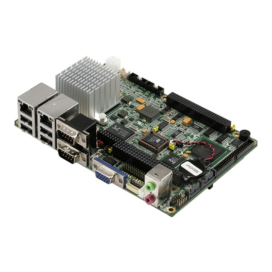
- Page 1 EPIC-5536 AMD Geode LX 800/900 (500/600MHz) Processors DDR SODIMM Up to 1GB Up to 24-bit TFT/LVDS LCD Panel 4 USB 2.0 / 5 COMs / 1 IDE/ 2 SATAI/ 1 CompactFlash/ Digital I/O EPIC-5536 Manual Rev.A 1st Ed. June 2008...
-
Page 2: Copyright Notice
AAEON assumes no liabilities resulting from errors or omissions in this document, or from the use of the information contained herein. AAEON reserves the right to make changes in the product design without notice to its users. - Page 3 E P I C B o a r d E P I C - 5 5 3 6 Acknowledgments All other products’ name or trademarks are properties of their respective owners. Award is a trademark of Award Software International, Inc. CompactFlash™...
-
Page 4: Packing List
Before you begin installing your card, please make sure that the following materials have been shipped: • 1 9657666600 Jumper Cap • 1 9681945600 Cable Kit for EPIC-5536 • 1 EPIC-5536 CPU Board w/ Heatsink • 1 Quick Installation Guide •... -
Page 5: Table Of Contents
E P I C B o a r d E P I C - 5 5 3 6 Contents Chapter 1 General Information 1.1 Introduction..............1-2 1.2 Features ..............1-3 1.3 Specifications ............1-4 Chapter 2 Quick Installation Guide 2.1 Safety Precautions ............ 2-2 2.2 Location of Connectors and Jumpers ....... - Page 6 E P I C B o a r d E P I C - 5 5 3 6 2.18 PC/104 Connector (CN3) ........2-13 2.19 PCI-104 Connector (CN4)........2-13 2.20 COM1/2 Connector (CN5)........2-14 2.21 Power Connector (CN6).......... 2-14 2.22 LVDS Connector (CN9)........... 2-15 2.23 Keyboard/Mouse Connector (CN10).......
- Page 7 E P I C B o a r d E P I C - 5 5 3 6 Chapter 3 Award BIOS Setup 3.1 System Test and Initialization........3-2 3.2 Award BIOS Setup ............ 3-3 Chapter 4 Driver Installation 4.1 Installation ..............
-
Page 8: Chapter 1 General Information
E P I C B o a r d E P I C - 5 5 3 6 Chapter General Information 1- 1 Chapter 1 General Information... -
Page 9: Introduction
(500/600MHz) processor or optional LX700 processor. This model features 200-pin DDR SODIMM and system memory is up to 1GB for DDR 333 or 512MB for DR400. Moreover, EPIC-5536 adopts AMD LX series and CS5536 as its chipset. EPIC-5536 deploys Realtek 8100C 10/100Base-TX chip that features two RJ-45 ports or optional RTL 8110S Gigabit LAN to display the transcendent performance of network connections. -
Page 10: Features
E P I C B o a r d E P I C - 5 5 3 6 1.2 Features Onboard AMD Geode™ LX 800/900 Processors SODIMM DDR 333 Max. 1GB and DDR400 Max. 512MB Up to 24-bit TTL/LVDS LCD Panel Dual 10/100Base-TX Ethernet (Optional Gigabit LAN) AC97 2.0 Codec 2 CH Audio PC/104+ Socket Expansions... -
Page 11: Specifications
E P I C B o a r d E P I C - 5 5 3 6 1.3 Specifications System Onboard AMD Geode LX800/900 (500/600MHz) processors (Optional LX 700) System Memory 200-pin DDR SODIMM x 1, max. 1GB for DDR333 & 512MB for DDR 400 Chipset AMD LX series + CS5536... - Page 12 E P I C B o a r d E P I C - 5 5 3 6 Storage Temperature F~176 F (-40 C~80 Operating Humidity 0%~90% relative humidity, non-condensing MTBF (Hours) 70,000 Board Size 4.53”(L) x 6.5” (W) (115mm x 165mm) Gross Weight 1.2 lb (0.5kg) Display: Support: CRT/LCD simultaneous display...
- Page 13 E P I C B o a r d E P I C - 5 5 3 6 Serial Port RS-232 x 3, COM TTL only/ GPS x 1, RS-232/422/485 x 1 Parallel Port SPP/ EPP/ ECP mode USB 2.0 x 4 PS/2 Port Keyboard + Mouse x 1 Digital I/O...
-
Page 14: Chapter 2 Quick Installation Guide
E P I C B o a r d E P I C - 5 5 3 6 Chapter Quick Installation Guide Notice: The Quick Installation Guide is derived from Chapter 2 of user manual. For other chapters further installation instructions, please refer to the user manual CD-ROM that came with the product. -
Page 15: Safety Precautions
E P I C B o a r d E P I C - 5 5 3 6 2.1 Safety Precautions Always completely disconnect the power cord from your board whenever you are working on it. Do not make connections while the power is on, because a sudden rush of power can damage sensitive electronic components. -
Page 16: Location Of Connectors And Jumpers
E P I C B o a r d E P I C - 5 5 3 6 2.2 Location of Connectors and Jumpers Component Side Chapter 2 Quick Installation Guide... - Page 17 E P I C B o a r d E P I C - 5 5 3 6 Solder Side Chapter 2 Quick Installation Guide...
-
Page 18: Mechanical Drawing
E P I C B o a r d E P I C - 5 5 3 6 2.3 Mechanical Drawing Component side Chapter 2 Quick Installation Guide... - Page 19 E P I C B o a r d E P I C - 5 5 3 6 Solder side Chapter 2 Quick Installation Guide...
-
Page 20: List Of Jumpers
E P I C B o a r d E P I C - 5 5 3 6 2.4 List of Jumpers The board has a number of jumpers that allow you to configure your system to suit your application. The table below shows the function of each of the board's jumpers: Jumpers Label... -
Page 21: List Of Connectors
E P I C B o a r d E P I C - 5 5 3 6 2.5 List of Connectors The board has a number of connectors that allow you to configure your system to suit your application. The table below shows the function of each board's connectors: Connectors Label... - Page 22 E P I C B o a r d E P I C - 5 5 3 6 CN18 LCD Inverter Power Connector CN19 Floppy Connector CN20 COM5/GPS Connector CN21 Power Output Connector CN23 Audio Connector (Line-in) CN24 Battery Wafer CN25 Compact Flash Connector CN26...
-
Page 23: Setting Jumpers
E P I C B o a r d E P I C - 5 5 3 6 2.6 Setting Jumpers You configure your card to match the needs of your application by setting jumpers. A jumper is the simplest kind of electric switch. It consists of two metal pins and a small metal clip (often protected by a plastic cover) that slides over the pins to connect them. -
Page 24: Cfd1 Selection (Jp1)
E P I C B o a r d E P I C - 5 5 3 6 2.7 CFD1 Selection (JP1) Function Master mode Slave mode (Default) 2.8 ATX Simulates AT Power (JP2) Function ATX Power ATX Power Simulates AT Power (Default) 2.9 CMOS Clear Selection (JP3) Function Clear CMOS... -
Page 25: Ttl Clock And Lvds Operating Selection (Jp6)
E P I C B o a r d E P I C - 5 5 3 6 2.12 TTL Clock and LVDS Operating Selection (JP6) Function Inverse Clock Normal Clock (Default) +3.3V for CN9 (Default) +5V for CN9 2.13 Fan Power Selection (JP7) Function +12V (Default) 2.14 AT/ATX Power Type Selection (JP8) -
Page 26: Lpt Connector (Cn2)
E P I C B o a r d E P I C - 5 5 3 6 2.17 LPT Connector (CN2) Signal Signal STB- AFDX PTD0 ERRX PTD1 PAR_INTX PTD2 SLINX PTD3 PTD4 PTD5 PTD6 PTD7 ACKX BUSY SLCT 2.18 PC/104 Connector (CN3) Standard PC104 ISA Connector 2.19 PCI-104 Connector (CN4) -
Page 27: Com1/2 Connector (Cn5)
E P I C B o a r d E P I C - 5 5 3 6 2.20 COM1/2 Connector (CN5) COM1 (Up) Signal Signal DCD1 RXD1 TXD1 DTR1 DSR1 RTS1 CTS1 COM2 (Down) Signal Signal DCD2 (422TXD-/485DATA-) RXD2 (422RXD-) TXD2 (422TXD+/485DATA+) DTR2 (422RXD+) DSR2... -
Page 28: Lvds Connector (Cn9)
E P I C B o a r d E P I C - 5 5 3 6 +12V +12V 2.22 LVDS Connector (CN9) Signal Signal Backlight enable LVDS Power TX1CLK# TX1CLK LVDS Power TX1OUT#0 TX1OUT0 TX1OUT#1 TX1OUT1 TX1OUT#2 TX1OUT2 TX1OUT#3 TX1OUT3 LVDS Power... -
Page 29: Irda Connector (Cn11)
E P I C B o a r d E P I C - 5 5 3 6 +5V with fuse MDAT MCLK 2.24 IrDA Connector (CN11) Signal IRRX IRTX 2.25 COM3 Connector (CN12) Signal Signal DCD3 RXD3 TXD3 DTR3 DSR3 RTS3 CTS3... -
Page 30: System Fan Connector (Cn14)
E P I C B o a r d E P I C - 5 5 3 6 2.27 System Fan Connector (CN14) Signal FAN Power FAN_TAC 2.28 Front Panel Connector (CN15) Signal Signal Power Button HD_LED +3.3V BEEP Power LED Reset 2.29 Digital I/O Connector (CN16) Signal... -
Page 31: Ttl Lcd Connector (Cn17)
E P I C B o a r d E P I C - 5 5 3 6 DIO_2 CN16 PIN2 Bit 6 U47 PIN21 (GPIO26) DIO_3 CN16 PIN3 Bit 5 U47 PIN22 (GPIO25) DIO_4 CN16 PIN4 Bit 4 U47 PIN23 (GPIO24) DIO_5 CN16 PIN5 Bit 3... -
Page 32: Lcd Inverter Power Connector (Cn18)
E P I C B o a r d E P I C - 5 5 3 6 LCD CLOCK LCD VSYNC LCD DE LCD HSYNC 2.31 LCD Inverter Power Connector (CN18) Signal LCD Inverter Power Backlight Control Backlight enable 2.32 Floppy Connector (CN19) Signal Signal... -
Page 33: Com5/ Gps Connector (Cn20)
E P I C B o a r d E P I C - 5 5 3 6 DIR# STEP# TRAK0# WPT# RDATA# HDSEL# DSKCHG# 2.33 COM5/ GPS Connector (CN20) Signal GPS LED VCC3.3-BAT. +3.3V 2.34 Power Output Connector (CN21) Signal +12V 2-20... -
Page 34: Audio Line-In Connector (Cn23)
E P I C B o a r d E P I C - 5 5 3 6 2.35 Audio Line-in Connector (CN23) Signal LINE_IN_R Audio GND LINE_IN_L 2.36 Battery Wafer (CN24) Signal Battery Power 2.37 CompactFlash Connector (CN25) Standard Compact Flash Connector (Type I & II) 2.38 IDE Connector (CN26) Signal Signal... -
Page 35: Vga Connector (Cn29)
E P I C B o a r d E P I C - 5 5 3 6 PID0 PID15 PDREQ PIOW# PIOR# PRDY Pull 330R to GND PACK# PIRQ14 PPDA1 ATA66_DET PPDA0 PPDA2 PPCS1# PPCS3# HDLED# 2.39 SATA Connector (CN27, 28) Standard SATA Connector 2.40 VGA Connector (CN29) Signal... -
Page 36: Standby Power Connector (Cn30)
E P I C B o a r d E P I C - 5 5 3 6 DDC_DAT HSYNC VSYNC DDC_CLK 2.41 Standby Power Connector (CN30) Signal PS_ON# +5V Standby 2-23 Chapter 2 Quick Installation Guide... - Page 37 E P I C B o a r d E P I C - 5 5 3 6 Below Table for China RoHS Requirements 产品中有毒有害物质或元素名称及含量 AAEON Main Board/ Daughter Board/ Backplane 有毒有害物质或元素 部件名称 铅 汞 镉 六价铬 多溴联苯 多溴二苯醚 (Pb)
-
Page 38: Chapter 3 Award Bios Setup
E P I C B o a r d E P I C - 5 5 3 6 Chapter Award BIOS Setup Chapter 3 Award BIOS Setup 3-1... -
Page 39: System Test And Initialization
3. The CMOS memory has lost power and the configuration information has been erased. The EPIC-5536 CMOS memory has an integral lithium battery backup for data retention. However, you will need to replace the complete unit when it finally runs down. -
Page 40: Award Bios Setup
E P I C B o a r d E P I C - 5 5 3 6 3.2 Award BIOS Setup Awards BIOS ROM has a built-in Setup program that allows users to modify the basic system configuration. This type of information is stored in battery-backed CMOS RAM so that it retains the Setup information when the power is turned off. - Page 41 Save CMOS value changes to CMOS and exit setup. Exit Without Saving Abandon all CMOS value changes and exit setup. You can refer to the "AAEON BIOS Item Description.pdf" file in the CD for the meaning of each setting in this chapter. Chapter 3 Award BIOS Setup 3-4...
-
Page 42: Chapter 4 Driver Installation
E P I C B o a r d E P I C - 5 5 3 6 Chapter Driver Installation 4 - 1 Chapter 4 Driver Installation... - Page 43 E P I C B o a r d E P I C - 5 5 3 6 The EPIC-5536 comes with a CD-ROM that contains all drivers and utilities that meet your needs. Follow the sequence below to install the drivers: Step 1 –...
- Page 44 E P I C B o a r d E P I C - 5 5 3 6 4.1 Installation: Insert the EPIC-5536 CD-ROM into the CD-ROM Drive. And install the drivers from Step 1 to Step 7 in order. Step 1 –Install LX-Graphic Driver 1.
- Page 45 E P I C B o a r d E P I C - 5 5 3 6 3. Click on Control Panel button 4. Click on System button 5. Select Hardware and click on Device Manager… 6. Double click on Entertainment Encryption/Decryption Controller 7.
- Page 46 E P I C B o a r d E P I C - 5 5 3 6 8. Click on Next 9. Select Search for a suitable driver…, then click on Next 10. Select Specify a location, then click on Next 11.
- Page 47 E P I C B o a r d E P I C - 5 5 3 6 8. Click on Next 9. Select Search for a suitable driver…, then click on Next 10. Select Specify a location, then click on Next 11.
- Page 48 E P I C B o a r d E P I C - 5 5 3 6 1. Creating a Drive Disk: copy the SATA driver from AAEON CD to floppy disk before install OS. Click on Step 7-VRAID_Driver_V5508 Click on VRAIDDrv (see below picture) Click on DriverDiskPrep.exe (see below picture)
- Page 49 E P I C B o a r d E P I C - 5 5 3 6 Click on the OS what you are going to install. Install Floppy or USB Floppy 4 - 8 Chapter 4 Driver Installation...
- Page 50 E P I C B o a r d E P I C - 5 5 3 6 Finish: driver disk ready. 2. Following are the raid configuration steps. Press <Tab> key to enter Raid BIOS setup (Raid BIOS only enable when SATA HDD connected) 4 - 9 Chapter4 Drivers Installation...
- Page 51 E P I C B o a r d E P I C - 5 5 3 6 Create Array 4 - 10 Chapter 4 Driver Installation...
- Page 52 E P I C B o a r d E P I C - 5 5 3 6 After Raid has been created, set this array bootable. 4 - 11 Chapter4 Drivers Installation...
- Page 53 E P I C B o a r d E P I C - 5 5 3 6 4 - 12 Chapter 4 Driver Installation...
- Page 54 E P I C B o a r d E P I C - 5 5 3 6 Now the Raid Array is ready for OS installation 3. Insert your Windows CD, and then restart the computer 4. Follow the on-screen instructions to begin the Windows installation.
- Page 55 E P I C B o a r d E P I C - 5 5 3 6 Note: When F6 is active, a prompt appears at the bottom of the screen for only 5 seconds. If you miss your chance to press F6, restart your computer.
- Page 56 E P I C B o a r d E P I C - 5 5 3 6 8. The computer reads the disk 9. When the SATA driver is found, press Enter. 4 - 15 Chapter4 Drivers Installation...
- Page 57 E P I C B o a r d E P I C - 5 5 3 6 10. Follow the on-screen instructions to complete the installation. After finish installing OS, you have to install VIA Raid management Utility. Setup RAID Management A.
- Page 58 E P I C B o a r d E P I C - 5 5 3 6 4 - 17 Chapter4 Drivers Installation...
-
Page 59: Appendix A Programming The Watchdog Timer
E P I C B o a r d E P I C - 5 5 3 6 Appendix Programming the Watchdog Timer Appendix A Programming the Watchdog Timer... -
Page 60: Programming
E P I C B o a r d E P I C - 5 5 3 6 A.1 Programming EPIC-5536 utilizes ITE 8712 chipset as its watchdog timer controller. ( K version ) Below are the procedures to complete its configuration and the AAEON intial watchdog timer program is also attached based on which you can develop customized program to fit your application. - Page 61 E P I C B o a r d E P I C - 5 5 3 6 Exit the MB PnP Mode. Undesired result may occur if the MB PnP Mode is not exited normally. (1) Enter the MB PnP Mode To enter the MB PnP Mode, four special I/O write operations are to be performed during Wait for Key state.
- Page 62 E P I C B o a r d E P I C - 5 5 3 6 hardware reset will automatically clear the bits, and does not require the software to clear them. Description Reserved Returns to the Wait for Key state. This bit is used when the configuration sequence is completed.
-
Page 63: Ite8712 Watchdog Timer Initial Program
E P I C B o a r d E P I C - 5 5 3 6 WatchDog Timer Time-out Value (LSB) Register (Index=73h, Default=00h) Description WDT Time-out value 7-0 WatchDog Timer Time-out Value (MSB) Register (Index=74h, Default=00h) Description WDT Time-out value 15-8 A.2 ITE8712 Watchdog Timer Initial Program .MODEL SMALL... -
Page 64: Appendix B I/O Information
E P I C B o a r d E P I C - 5 5 3 6 Appendix I/O Information Appendix B I/O Information... -
Page 65: I/O Address Map
E P I C B o a r d E P I C - 5 5 3 6 B.1 I/O Address Map Address Description User Address 000-01F DMA Controller #1 000-000F 020-03F Interrupt Controller #1, Master 020-021 040-05F System Time 040-043 060-06F 8042 (Keyboard Controller) -
Page 66: Irq Mapping Chart
E P I C B o a r d E P I C - 5 5 3 6 B.3 IRQ Mapping Chart IRQ0 System Timer IRQ8 System CMOS / Real time clock IRQ1 Keyboard IRQ9 Microsoft ACPI – Compliant system IRQ2 Cascade to IRQ Controller IRQ10 COM3 IRQ3 COM2... - Page 67 E P I C B o a r d E P I C - 5 5 3 6 Appendi Mating Connecotor C - 1 Appendix C Mating Connector...
-
Page 68: Appendix C Mating Connector
E P I C B o a r d E P I C - 5 5 3 6 C.1 List of Mating Connectors and Cables The table notes mating connectors and available cables. Connector Function Mating Connector Available Cable P/N Label Cable Vendor Model no... - Page 69 E P I C B o a r d E P I C - 5 5 3 6 1.25mm Pitch 40 pins TTL LCD TFT LCD CN17 e-call (e-call.0110-01-55 Connector cable 3-400 or compatible) 2.0mm Pitch 5 Inverter pins (CATCH CN18 Catch Inverter...
Need help?
Do you have a question about the EPIC-5536 and is the answer not in the manual?
Questions and answers