Ingersoll-Rand X8I Operator's Manual
System automation
Hide thumbs
Also See for X8I:
- Operator's manual (502 pages) ,
- Detailed description (11 pages) ,
- Operator's manual (11 pages)
Table of Contents
Advertisement
Before installing or starting this unit for the first
time, this manual should be studied carefully to
obtain a working knowledge of the unit and or the
duties to be performed while operating and
maintaining the unit.
RETAIN THIS MANUAL WITH UNIT. This Technical
manual contains IMPORTANT SAFETY DATA and
should be kept with the unit at all times.
More Than Air. Answers.
Online answers: http://www.air.irco.com
Ingersoll Rand
System Automation
Operator's Manual
C.C.N. : 80444060
REV.
DATE : MAY 2008
X8I
: B
Advertisement
Table of Contents

Related Manuals for Ingersoll-Rand X8I


Summary of Contents for Ingersoll-Rand X8I
- Page 1 Ingersoll Rand System Automation Operator’s Manual Before installing or starting this unit for the first time, this manual should be studied carefully to obtain a working knowledge of the unit and or the duties to be performed while operating and maintaining the unit.
-
Page 2: Table Of Contents
INSTALLATION ................3 DISPLAY ITEM STRUCTURE...........27 OPERATION ..................3 NORMAL OPERATIONAL DISPLAY (MENU PAGE P00) 27 MAINTENANCE AND REPAIR ..........3 ACCESSING THE X8I CONFIGURATION SCREENS ..27 SECTION 4 — COMPRESSOR CONNECTION AND CONTROL ................5 USER LEVEL MENUS ..............29 SERVICE LEVEL MENUS ............30 COMPRESSOR CONNECTION AND CONTROL ....5... -
Page 3: Section 2 - Introduction
Maintenance, repairs or modifications must only be main power supply and the X8I. carried out by competent personnel under qualified • The X8I should be mounted in such a location as to supervision. allow operational and maintenance access without •... - Page 4 Attach a label to the isolator switch and to the • The X8I must only be cleaned with a damp cloth, unit stating ‘WORK IN PROGRESS - DO NOT using mild detergents if necessary. Avoid the use of APPLY VOLTAGE’ . Do not switch on electrical any substances containing corrosive acids or alkalis.
-
Page 5: Section 4 - Compressor Connection And Control
All Nirvana Compressors, 20 HP (15KW) and above require the irV-485 Gateway. ir-485 The EXP Box connects to the X8I controller via a two wire, dedicated RS485 network The ir-485 Gateway interface module is installed within the compressor control cabinet and connected to the X8I Use Belden 9841 or Equivalent In Grounded Conduit using Belden 9841 or equivalent RS485 cable. -
Page 6: Pressure Detection And Control
Remote Compressor Management; EX Box (option) The VSD Box connects to the X8I controller via a two wire, RS485 network utilizing the ir485 protocol The EX Box is an ‘EXtension’ to the X8I providing additional ‘ir-PCB’ connectivity. Each air compressor in a system, that requires VSD Box integration, must be equipped with an individual VSD The EX Box will typically be used to provide ‘ir-PCB’... -
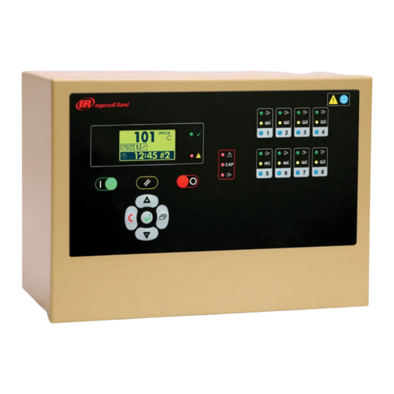
Page 7: X8I Main Display
X8I MAIN DISPLAy User Interface : System Pressure Value System Pressure Units Unit Status Unit Active Functions 17:30 User Menu Item System Alarms (Warning) : Unit Run Indicator (green LED) Unit Alarm Indicator (Red LED) System Alarms (Warning) : Group Compressor Fault Insufficient Capacity Alarm (Warning) -
Page 8: Section 5 - Installation Overview
Reference X8I Application and Interconnect Guide For Compressors The RS485 Network is a Serial, Point to Point Wiring Connections Between The X8I, The ir-485 or irV- Communication Network Refer to the X8I Application and 485 Gateway and The Compressor, S3 Direct Connects, and Interconnect Guide For Wiring Details and Connectivity. -
Page 9: Installation
DEMAND (DRy) SIDE PRESSURE CONTROL UNIT LOCATION The X8I can be mounted on a wall using conventional bolts. The X8I can be located remotely from the compressors as long as it is within 330 feet (100 meters) of cable length when connecting compressors directly with ir-PCB’s. -
Page 10: Pressure Sensor Connection
X8I providing protection and voltage isolation. Consult the X8I Interconnect and Application Guide prior to the installation of the X8I and the ir-PCB to the air compressor. Pressure Sensor Wiring and Location... -
Page 11: Ir-485 And Irv-485 Gateway Module
Gateway and Interconnect Guide For Wiring Details and Connectivity. The cable used between the X8I and the ir-485 and irV- 485 Gateways is Belden 9841 (or equivalent). It should be The following example details the “correct” method of run in grounded conduit and should not be greater than wiring the RS485 Network 4000 feet (1219 meters) in length. - Page 12 If it is necessary to follow the route of power supply cables for a short distance (for example: from a compressor X8I to a wall along a suspended cable tray) attach the RS485 or signal cable on the outside of an earthed cable tray such that the cable tray forms an earthed electrical interference shield.
-
Page 13: Section 6 - Control Features And Functions
“b” is reached. Once point “b” is reached, the X8I will load the next compressor in the sequence to match the air demand. This cycle will repeat as long as the X8I is able to keep the system air pressure between PH and PL. - Page 14 The most accurate way to determine the size of air The X8I’s factory default DA setting of “1” is adequate for receivers or the additional volume required would the majority of compressed air systems but may need...
-
Page 15: Standard Control Features And Functionality
Lead position. By assigning compressor 1 a STANDARD SEQUENCE CONTROL STRATEGIES priority of 1 and the other three compressors a priority The standard configuration of the X8I provides ENER of 2, the variable speed compressor will always remain at (Energy Control) sequence control strategy, Priority... - Page 16 4. To ensure of the X8I. The X8I can be instructed to change among that compressor 1 is always at the front of the sequence the tables at any time based on the configuration of the and compressor 4 is always at the end of the sequence, pressure schedule.
- Page 17 See the Quick Setup Manual. pressure as quickly as possible. Normal operational control will then begin. If the X8I is able to complete the transition in less time than is allotted without threatening energy efficiency Three prefill modes are available. ‘Backup’ and ‘Standard’...
-
Page 18: Alternate Control Features And Functionality
Energy Control Mode (ENER) is the STANDARD control Fault item. mode of the X8I. Alternate control strategies of the X8I are ‘Insufficient Capacity’ is available as a dedicated data the basic FILO (First in / Last Out) and EHR (Equal Hours communications item. - Page 19 These readings are viewable and adjustable in the X8I C01 setting screens. The X8I will use these values during EHR mode. The running hours on the X8I should be routinely checked to see that they match the...
-
Page 20: Section 7 - Display And Menu Operation
SECTION 7 — DISPLAy AND MENU OPERATION The Main Display and the keypad and navigation buttons on the X8I are depicted below and provide the following functionality: User Interface : System Pressure Value System Pressure Units Unit Status Unit Active Functions... - Page 21 Unit Functions: The following Icons are used by the X8I to display the Controller Active Functions. Operating Mode : EHR - Equal Hours Run FILO - Timer Rotation ENER - Energy Control Active Functions : Power Failure Auto-Restart System Pressure Status : Table #1 Increasing to normal operational levels (Prefill,...
- Page 22 Main Manu Real Time Clock 17:30 17.30 (24r system) # 1 = Monday to # 7 = Sunday Compressor Detailed Status: A: 100% User Manu A number of User menu information displays are available that can be accessed directly from the front panel using the Up and Down navigation buttons.
-
Page 23: Indicators
Fast Flash: Shutdown (Trip) Slow Flash – One or more compressors Alarm Slow Flash: Alarm (Warning) (Warning) The X8I fault indicator does not indicate compressor b) Insufficient Capacity Alarm (Warning) fault states; see Compressor Status Indicators. On – Insufficient Capacity... - Page 24 Compressor Identification Item values 6 and 7 are only shown if compressor type is IRV-485 (variable capacity/speed). Each compressor connected to the X8I will have a unique assigned compressor identification number; starting at compressor 1 increasing sequentially to the number of...
- Page 25 If the power failure auto-restart function is enabled the X8I will automatically start, when power is restored after a disruption or failure, if the X8I was in a ‘started’ state when the power disruption or failure occurred. The X8I will not automatically restart if the X8I was in...
-
Page 26: Section 8 - Commissioning
230Vac (+-10%), 50/60Hz). Please refer to the X8I Quick Setup Manual for instruction 2. Open the front panel of the X8I and check the to accomplish this. location of the link wire(s) connected to the OPTIONAL FEATURES AND FUNCTIONS “Voltage Selection”... -
Page 27: Section 9 - System Configuration
SECTION 9 — SySTEM CONFIGURATION DISPLAy ITEM STRUCTURE ACCESSING THE X8I CONFIGURATION SCREENS Operational system status and values are accessible from the normal user display. To view status or values that are Access Code: not normally visible on the default screen, press UP or Access to adjustable menu page items is restricted by DOWN. - Page 28 Item is view only (not adjustable) or in instances number ‘01’ (for example: P01-01.01). where the item cannot be adjusted while the X8I is in an operational state; stop the X8I first.
-
Page 29: User Level Menus
USER LEVEL MENUS User Configuration TABLE #1 01 Ct Real Time Clock Set 02 PS Pressure Schedule Enable 01 PH High Pressure Set Point 03 AR Auto Restart Enable 02 PL Low Pressure Set Point 04 RP Rotation Interval 03 Pm Minimum Pressure Alarm 05 TS Default Table Select... -
Page 30: Service Level Menus
XPM Expansion Module C:5-8 Diagnostic Menu Sensor Calibration only available when applicable EXP Expansion Box is 01 1O Pressure Offset installed and registered (detected) by the X8I. 02 1R Pressure Range Digital Input #1 (Di 1) Digital Input #8 (Di 8) -
Page 31: X8I Configuration Screens
‘n’ = number of compressors in the system. 8 is the when the ‘Table’ is active. The default setting for this maximum number of compressors for the X8I parameter is 98 PSI. The values for this parameter are: The highest value for the Low Pressure setpoint = PH Priority Settings: “High Pressure”... - Page 32 The default setting for this Schedule consists of 28 individual settings that instruct parameter is A . the X8I to change from one Table to another, or put the system into Standby mode, dependant on time of (Represents the pre-fill function is in Automatic day and day of the week.
- Page 33 P02 - PP Prefill Pressure The Pressure Setpoint used by the X8I to determine if the Pre-fill Function is required at start up. If pressure is at, or 08 Ct 1 . 18:00 above, this setting at system startup, the prefill function will be abandoned immediately and normal pressure control and sequence strategy will be implemented.
- Page 34 S01 - RP Rotation Interval S01 - TS Default Table Select The X8I provides a Timed rotation event that can be This parameter determines the ‘Table’ that will be used automatically triggered on a routine basis using a by default when ‘Pressure Schedule’ is not active and no pre-determined interval, a pre-determined time each table is selected remotely on a digital input.
- Page 35 S02 - CF Stop Control Function This parameter determines if the X8I maintains control of the compressors when the X8I is stopped. The default 01 P> setting for this parameter is . (Represents the Stop Control Function is disabled) The values for this...
- Page 36 When inhibited the Restricted Capacity Alarm panel S02 - PC Pressure Change Time indication will still function; alarm code generation and This parameter adjusts the time that the X8I will remote alarm indications are inhibited. implement a smooth and controlled change from one ‘target’...
- Page 37 S02 – AI Auxiliary Digital Input S02 – AO Auxiliary Output Function S02 10.01 S02 11.01 01:D1 01:AF The function of the Auxiliary input. The function of the Auxiliary output ‘volt-free’ relay contacts. 01:DI Digital Input 01:AF Any Fault No defined function but status (0=normal, 1=activated) Any Alarm (Warning), Shutdown (Trip) or Compressor Not Available.
- Page 38 This parameter determines the Communication Broadcast the detected pressure display matches the applied Timeout between the X8I and the I/O box. If the I/O Box pressure. An applied pressure equal too, or greater fails to communicate on the RS485 network within the than, the nominal system working pressure is set ‘Communications Broadcast Timeout’...
- Page 39 C01 – 01 to C01 – ‘n’ Run Hours’ ‘n’ = number of compressors in the system. 8 is the maximum number of compressors for the X8I This parameter is set to match the running hours of each compressor. Record of detected ‘running’ hours for each compressor.
- Page 40 C03 – 01 to C03 – ‘n’ Compressor Connection’ C03 01.01 ‘n’ = number of compressors in the system. 8 is the maximum number of compressors for the X8I 100 % This parameter sets the type, method of connection, and...
-
Page 41: X8I Compressor Connectivity And Functional Settings
‘Standby’ or ‘Auto Restart’ condition. Example Compressor 1 is a VSD: This time is used by the X8I for accurate recording of ‘run hours’ (EHR mode), operational calculations and Max CFM = 700 other data recording applications. An accurate time is Max Output Capacity 700/700 = 100% important for successful X8I operation. - Page 42 System capacity. When the compressor is detected as operating below the % Minimum Efficiency value for a period of time the X8I will immediately re-evaluate utilization and re-configure, if possible, to utilize a the smaller capacity, more efficient compressor, or combination of compressors.
- Page 43 The error code • Error code symbols (if applicable) • The date the error occurred • The time the error occurred • The active operational functions of the X8I at the time the error occurred; (see: X8I Status Display for Icons)
- Page 44 An independent measuring device can be used to check the displayed electrical measurement. A1: System Pressure, 4-20mA The X8I is equipped with comprehensive diagnostic functions. Each input can be examined individually and A2: Digital: ir-PCB #4 – Alarm/Serv.
- Page 45 V outputs. Set the analog output to the following to switch each ‘V’ output as required. o only available when applicable EXP Expansion Box is installed and registered (detected) by the X8I. 4.0mA All ‘V’ outputs OFF X8I Controller Diagnostics: 7.0mA V1 = ON;...
-
Page 46: Section 10 - Fault Codes
X8I COMPRESSOR FAULT INDICATIONS, Trip (Shutdown): TyPES, AND CODES: In the event of a unit or system “fault” the X8I will display a fault code. The fault code becomes an item in the user 1sec operational display menu. If more than one “active” fault occurs, each will be displayed as a separate item in the The Fault LED will ‘fast flash’... - Page 47 SyS.05 Remote Alarm (Warning) The controller’s main power supply must be removed and re-applied to reset this condition. Auxiliary Input Function ‘AA’ E5001: Internal memory failure The auxiliary Input is set for ‘Alarm (always active)’ function and is in a Fault condition. The unit’s controller has detected disruption to the internal permanent application memory storage (FLASH).
-
Page 48: Section 11 - Parts List
SECTION 11 — PARTS LIST Item Part No. Description Item Part No. Description 22194773 XI Installation Kit 42659250 X8I, Kit 80444078 Quick Setup Guide 23242159 Unit, X8I 80444086 Manual, User CD 42659268 Unit, Controller 42659284 Unit, XPM-PSU24 39265913 Unit, XPM-TAC24... -
Page 49: Section 12 - Diagrams
SECTION 12 — DIAGRAMS T1-46-321-R6-DiC-CG Terminal PCB +VDC +VDC A-GND C031 C032 +VDC C019 C010 C020 C010 C021 XPM-LED C022 C011 C023 C024 C012 C025 C013 C026 C019 C014 C027 C015 R-SEQ C016 C024 C034 150k C017 C011 C018 150k C019 C012 C012... -
Page 50: Connection Diagram
Connection Diagram Terminal PCB 115V 'UL' @ 5A maximum. Auxiliary Output #1 Auxiliary Input #1 330ft (100m) max Multi485 330ft (100m) max System Pressure 4-20mA +20VDC Ready/Run Alarm/Serv. 330ft (100m) max LOAD IR-PCB 6-core IRV-PCB 7-core +20VDC Ready/Run Alarm/Serv. 330ft (100m) max LOAD IR-PCB 6-core IRV-PCB 7-core... -
Page 51: Xpm-Tac24
XPM-TAC24 BLUE BLACK ORANGE BROWN WHITE GREEN VIOLET T3.15A T1.6A T1.6A T1.0A VOLTAGE SELECT 230V +-10% 230V 115V 115V +-10% T1.0A 5x20mm 24Vac/2 24Vac/1 N L E earthed isolated... -
Page 52: X8I Commissioning Form
X8I COMMISSIONING FORM Customer Contact Customer Ref: Phone Internal Ref: Installation/Site Commission Date Software Ser No. Commission Engineer Comp #1 Manufacturer Comp #1 Model/Type Comp #1 Working Pressure bar/psi VA Hz Comp #1 Full Load Capacity Comp #2 Manufacturer Comp #2 Model/Type... - Page 53 High Pressure Set Point psi/bar Low pressure Set Point psi/bar Minimum Pressure Alarm psi/bar Sequence Rotation Mode FILO ENERGY Comp #1 Priority Comp #2 Priority Comp #3 Priority Comp #4 Priority Comp #5 Priority Comp #6 Priority Comp #7 Priority Comp #8 Priority High Pressure Set Point psi/bar...
- Page 54 Prefill Function !>X Prefill Time Prefill Pressure psi/bar Primary Compressors 1 2 3 4 5 6 7 8 9 10 11 12 Backup Compressors 1 2 3 4 5 6 7 8 9 10 11 12 Pressure Schedule Auto Restart Rotation Interval Default Table Select Number of Compressors...
- Page 55 Compressor #1 Hours Compressor #2 Hours Compressor #3 Hours Compressor #4 Hours Compressor #5 Hours Compressor #6 Hours Compressor #7 Hours Compressor #8 Hours Compressor #1 Type IR-PCB IRV-PCB IR-485 IRV-485 Start Time Max Capacity Min Capacity Min Efficiency Compressor #2 Type IR-PCB IRV-PCB IR-485...
Need help?
Do you have a question about the X8I and is the answer not in the manual?
Questions and answers