Lionel FasTrack Owner's Manual
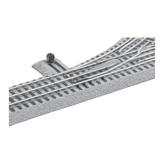
Train tracks, command control remote
switch
Hide thumbs
Also See for FasTrack:
- Owner's manual (4 pages) ,
- Owner's manual (12 pages) ,
- Owner's manual (9 pages)

Subscribe to Our Youtube Channel
Related Manuals for Lionel FasTrack


Summary of Contents for Lionel FasTrack
- Page 1 71-2045-250 10/10 Lionel Lionel Command Control Remote Command Control Remote Switch Switch Owner’s Manual Owner’s Manual 71-2045-250 Generic CC switch.indd 1 10/7/10 2:44 PM...
-
Page 2: Table Of Contents
You may choose to remove the installed manual controllers and forgo that wiring all together. The switch connects easily to other FasTrack track sections. Use the switch to join two track loops, create a switching yard, or add a siding. Run your trains around your layout... -
Page 3: Joining The Fastrack Track Sections
Joining the FasTrack track sections asTrack track sections join together easily. With interlocking roadbed sections Rail tab and large rail tabs, the track fits together securely so you always get good electrical contact. Refer to Figure 1 to see how to join the track sections. -
Page 4: Operating The Switch In Conventional Mode
Operating the switch in conventional mode ou may operate the switch using the controller or the illuminated switch lamp on the roadbed. Refer to Figure 3. To operate the switch using the controller, power up the track, then pull the lever to the opposite position. -
Page 5: Changing The Switch Stand Location
Changing the switch stand location ou may choose to position the switch stand either inside or outside the loop of track. Follow these steps and refer to Figure 4 to change the location of the switch stand. 1. Remove the two screws that secure the small roadbed section to the switch and lift away the roadbed section. -
Page 6: Operating Your Switches In Command Control Environment
Command Control operations Operating your switches in the Command Control environment our Command-equipped switch Example Address Switch #1 comes factory-programmed with Set PowerMaster to CMD or traditional a switch ID# of “1.” To get your switch power supplies to full throttle (no more in action, set PowerMasters to CMD than 19 volts) or set all power supplies on full (no... -
Page 7: Programming Your Switches
Command Control operations continued Programming your switches Program button Figure 5. Switch program button Programming: 1. Make sure that the command base is on and properly installed. 2. Power up the track. 3. Press and hold the program button for 1 to 2 seconds. The lantern will start to blink. 4. -
Page 8: Train Route Information
Command Control operations continued Programming your switches Soft Set Programming The TMCC switch incorperates “Soft Set Technology” which allows the operator to change the ID# (1-99) without physically activating the program button. This is great for switches that are not easily accessable. 1. -
Page 9: Routing The Controller Cable
Routing the controller cable he controller cable has been routed through the notch on the curved side of the roadbed at the factory. You may choose to route the controller cable through the notch on the straight side of the roadbed. As illustrated in Figure 7, remove the notch section from the straight side of the roadbed and bend the metal tabs to free the controller cable. -
Page 10: Mounting The Controllers
Mounting the controllers f you have multiple switches and controllers, you may choose to snap the interlocking controller bases together and mount them to your control panel using screws. To join the controller bases, snap the bases together on a flat surface as illustrated in Figure 8. Drive screws through the holes in the controller bases to secure the controllers to your layout. -
Page 11: Powering The Switch Through A Separate Power Supply
(LEDs). The LEDs are expected to last for the life of the switch and are not user serviceable. See your authorized Lionel Service Center if your LEDs require service. 71-2045-250 Generic CC switch.indd 11... -
Page 12: Limited Warranty/Lionel Service
(or copy) from an Authorized Lionel Retailer*, will at the discretion of Lionel LLC, be repaired or replaced, without charge for parts or labor. In the event the defective product cannot be repaired, and a suitable replacement is not available, Lionel will offer to replace the product with a comparable model (determined by Lionel LLC), if available.
Need help?
Do you have a question about the FasTrack and is the answer not in the manual?
Questions and answers