Table of Contents
Advertisement
A U T O M A T I C
T R A N S M I S S I O N
M U L T I - C H A N N E L
T W O - W A Y
L C D
R E M O T E
S T A R T E R
S Y S T E M
W I T H
V I R T U A L
T A C H
S Y S T E M
( A S
P R G - 1 0 0 0
C O M P A T I B L E )
CT-3400 TW
Installation Guide
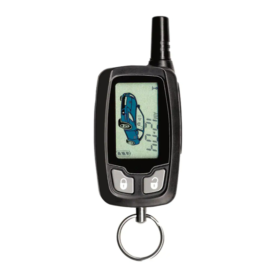
A note concerning the battery inside the transmitter:
Depending on the usage of the transmitter, the battery can last anywhere between 3 to 6
months. When the battery is low, it the transmitter will emit two beeps in a repetitive
cycle. At that point you should replace your battery with a new one. That is why we
recommend that you keep a spare battery somewhere handy such as the glove
compartment.
Notice
The manufacturer will accept no responsibility for any electrical damage resulting from improper installation of
the product, be that either damage to the vehicle itself or to the unit. This unit must be installed by a certified
technician using all safety devices supplied. Only registered technicians will be eligible to use the ProStart
technical support telephone service.
Please review the Installation Guide carefully before beginning any work.
Warning
This unit is designed for vehicles with an automatic transmission only. Before installing the unit, test that the
vehicle will not start if the gear select lever is in the "Drive" position. If the vehicle starts in gear, install a manual
transmission car starter instead.
DOC. 2.53
- CT-3400TW -
-September 4, 2007 -
- MO -
Assembled in Canada
Advertisement
Table of Contents

Related Manuals for ProStart CT-3400 TW


Summary of Contents for ProStart CT-3400 TW
-
Page 1: Installation Guide
This unit must be installed by a certified technician using all safety devices supplied. Only registered technicians will be eligible to use the ProStart technical support telephone service. -
Page 2: Table Of Contents
• 1 – Plug-in 2-volt LED • 1– Five-button Multi-channel Two-way • 1 – 6-pin Main Ignition Harness LCD Transmitter • 1 – 5-pin Secondary Harness • 1 – Antenna Interconnect Cable • 1 – 2-pin Secondary Harness P. 2 Installation Guide CT-3400 TW... -
Page 3: Installation Tools
The PAB is mounted on the side of the unit. equipped with air bags and anti-theft radios This push button mimics the hood-pin switch in ♦ Never ground the control unit to the order to avoid having to get out of the vehicle steering column. CT-3400 TW Installation Guide... -
Page 4: Harness Description
Use the 5th relay (pin F) and output extra relays to power up any extra . wires if necessary. DO NOT JUMP WIRES at the switch, this will compromise the OEM electrical IGNITION P. 4 Installation Guide CT-3400 TW... -
Page 5: 5-Pin Secondary Harness
There is a also a negative Parking Light output. Only one of these output two different outputs needs to be connected. 12-Pin Accessories Harness This harness has the remaining wires used in some remote starter installations as well as the optional user convenience outputs. CT-3400 TW Installation Guide... - Page 6 ): When the external trigger wire is START/STOP programmed to trigger the starter a ground pulse on this line will start or stop the engine. Option 3 ((-) Input Key Sense): When the external trigger wire is programmed P. 6 Installation Guide CT-3400 TW...
- Page 7 Minimum waiting time is 3 seconds. Maximum waiting time is 18 seconds. If no Glow-plug wire is found on the vehicle, the Glow-plug input on the Remote Car Starter may be “timed out”. The Remote Car Starter will power CT-3400 TW Installation Guide...
-
Page 8: 2-Pin Harness
“ON” for 20 seconds flash the hood pin as this will bring up the events playback and will not bring you the programming centre. You now have 20 seconds to select one of the sub- menus. P. 8 Installation Guide CT-3400 TW... -
Page 9: The Programming Assistance Button (A.k.a. Pab)
When getting into the Programming Option Mode, the Parking Lights will flash once, twice depending on the option you have entered. The unit will stay in Programming Mode until the Hood Pin-switch or the CT-3400 TW Installation Guide... - Page 10 To select one of four options, press the appropriate button on the transmitter: • button = Option 1 LOCK • button = Option 2 UNLOCK • button = Option 3 TRUNK • button = Option 4 START/STOP • then button = Option 5 LOCK Table 4 P. 10 Installation Guide CT-3400 TW...
-
Page 11: Programming Options
OFF) OPTION 2 DISABLED OPTION 3 ENABLED (with starter kill will flash when the starter kill engages. This option should be selected ONLY if the starter kill is installed.) CT-3400 TW Installation Guide P.11... - Page 12 FUNCTION 1 – Multi-Level Features OPTION 1 Multi-car Features, Basic Features, Customized Features OPTION 2* Basic Features, Multi-car Features, Customized Features OPTION 3 Customized Features, Multi-car Features, Basic Features OPTION 4 Basic Features, Customized Features, Multi-car Features P. 12 Installation Guide CT-3400 TW...
-
Page 13: Virtual Tach System
No manual adjustments are necessary. However, you should go through the Tach programming procedure every time a new Unit is installed. FLASH the Hood Pin Switch (see p. 8). Before the 20 seconds have passed. Press and hold the Brake Pedal. CT-3400 TW Installation Guide P.13... -
Page 14: Horn Honk Timing
Ignition Re-lock When ignition is (but not under remote start) and a door is opened and closed, the system will re-lock all doors next time the brake pedal is pressed. P. 14 Installation Guide CT-3400 TW... -
Page 15: Lock Pulse Duration
While the Engine is running, press on the transmitter until the LOCK, UNLOCK START/STOP parking lights come on. • Pressing will unlock the doors. LOCK UNLOCK • Pressing will leave the doors as they are. START/STOP CT-3400 TW Installation Guide P.15... -
Page 16: Turbo Mode
The system will be rearmed only once. Extra rearm pulses will not be sent when is pressed LOCK several times. (Certain factory alarms are affected when additional rearm pulses are sent once the system is armed.) P. 16 Installation Guide CT-3400 TW... -
Page 17: Secure Lock
Zone 3 Bypass is used as a trunk pin (Mode 3, Function 5, Option 1). Programmable External Trigger The External Trigger wire can be connected to a trunk pin-switch generating a negative signal when the trunk is open. CT-3400 TW Installation Guide P.17... -
Page 18: Smart Ignition Locks
5 times quickly. TRUNK The parking lights will flash 5 times quickly. (Otherwise you may also simply press the buttons repeatedly, until you get the parking light flashes.) P. 18 Installation Guide CT-3400 TW... -
Page 19: Resetting The Module (Without The Plug-In Valet Button)
• The range will be significantly lower in a crowded parking lot than in open space. • Always hold the transmitter high, approximately at shoulder height. Holding the transmitter against your chin will also increase your range. CT-3400 TW Installation Guide P.19... - Page 20 • Windows and windshields tinted with lead or metallic tints will decrease the operating range. • The antenna cable may have been cut and/or is grounded out on the chassis. Try using another cable. The receiver may be faulty. Try replacing it with another. P. 20 Installation Guide CT-3400 TW...
-
Page 21: Testing
Always make all your connections before plugging in the module, and be sure to test all functions properly before closing up the installation. Show the customer where the valet switch has been installed and place the warning label in a visible location under the hood. CT-3400 TW Installation Guide P.21... -
Page 22: Diagnostics (Parking Lights)
Locking or unlocking a door (with Door pulses configured to 4 sec.) • ON 20 seconds The hood pin has been flashed and you now have access to the programming options. Constant flashes • Panic mode is triggered. up to 25 sec. P. 22 Installation Guide CT-3400 TW... -
Page 23: Installation Order
This will protect the wires from rubbing against the bare metal and possibly shorting out. If you are installing an Alarm / starter combo module, mount the siren in the engine compartment at this time. CT-3400 TW Installation Guide P.23... - Page 24 - Program the Tach Signal - Change the programming of the options, if necessary - Test the module's operations If all of the testing is successful the install is complete, and the vehicle can be put back together. P. 24 Installation Guide CT-3400 TW...
-
Page 25: A Basic Introduction To The Relay
Remember, there is no polarity on a relay’s coil. This means that you may apply positive from the battery to either terminal 85 OR 86, and then Ground the OTHER terminal to activate the relay. In other words, you may use either a positive or negative trigger to energize the relay. CT-3400 TW Installation Guide P.25... - Page 26 Isolated for a reason, the wiring of the remote star module should reflect this.) The relay connections: 85: Connects in parallel to the Ignition 1 output from the remote start module. This becomes the positive side of the coil. P. 26 Installation Guide CT-3400 TW...
- Page 27 When the remote start module powers the Park lights, the OEM park light wire is opened, and power from the remote start module is sent only to the actual Parking Lights ( from 87 through 30). CT-3400 TW Installation Guide P.27...
- Page 28 “Starter Side” of the of the starter wire. 87A: Connects to the “Key Side” of the cut OEM starter wire. 30: Connects to the “Starter Side” of the cut OEM start wire. P. 28 Installation Guide CT-3400 TW...
-
Page 29: Troubleshooting Q & A
Does the light on the remote control turn on when you press the button? • Is the Ignition wire connected properly? • Are you waiting too long between programming steps? • After flashing the hood pin turn the key to ON, WAIT for 2 seconds. CT-3400 TW Installation Guide P.29... - Page 30 10. The factory alarm goes off when I start by remote. Did you hook the disarm wire? • Do you have the correct OEM disarm wire? • Did you program the disarm wire? (CT-3100/3160 only) • P. 30 Installation Guide CT-3400 TW...
- Page 31 22. Sometimes I have to press button I twice to lock my doors. Normal on 3100/3160 if you wait past the starter kill arm cycle (approx. 35 seconds) • Program toggle mode. (3100/3160 only) • CT-3400 TW Installation Guide P.31...
- Page 32 Door locks are reverse polarity, and not positive trigger. • 28. I blow fuses every time I try the remote Trunk release using relay. Trunk release is reverse polarity, and not positive trigger. • P. 32 Installation Guide CT-3400 TW...
Need help?
Do you have a question about the CT-3400 TW and is the answer not in the manual?
Questions and answers