
Related Manuals for Arbiter Systems 1084A


Summary of Contents for Arbiter Systems 1084A
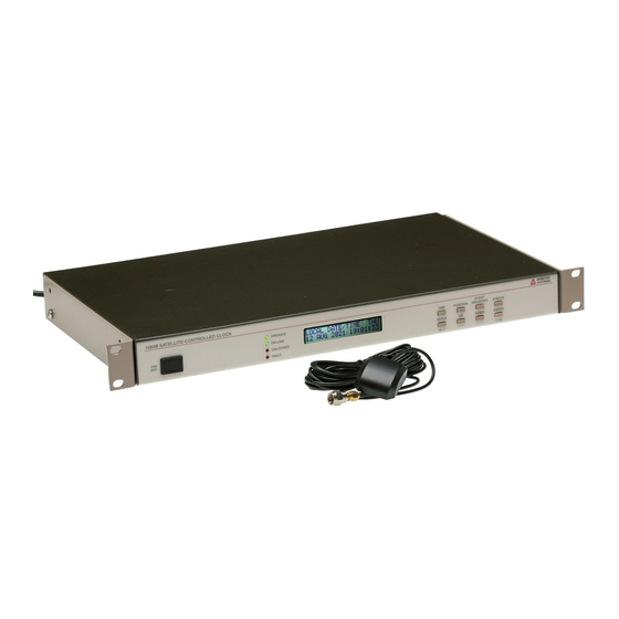
- Page 1 MODEL 1084A/B/C SATELLITE-CONTROLLED CLOCK OPERATION MANUAL ARBITER SYSTEMS, INC. PASO ROBLES, CA 93446 U.S.A. WWW.ARBITER.COM...
- Page 2 Description This manual is issued for reference only, at the convenience of Arbiter Systems. Reasonable effort was made to verify that all contents were accurate as of the time of publication. Check with Arbiter Systems at the address below for any revisions made since the original date of publication.
- Page 3 See Contact Information on page ii. “Limited Lifetime” means that Arbiter Systems will repair or replace the defective component as long as com- ponents are available and for no more than five years after the product has been deemed obsolete.
- Page 5 Startup and Basic Operation Appendix A Specifications and Technical Details Appendix B Using Surge Arresters Appendix C Options List Appendix D CE Mark Certification Appendix E Statement of Compliance Index Copyright Arbiter Systems Incorporated February 2016 All rights reserved. International copyright secured. PD0016100AJ...
-
Page 7: Table Of Contents
3.2.2 Option 07, Connecting Power to the 1084A/B/C ....12 3.3 Option 08, 10 to 60 Vdc Power With Terminal Power Strip and Surge Withstand . . 13 3.3.1... - Page 8 viii CONTENTS 3.7.1 Connecting an Event Input at P3 or Main RS-232 Port ... . 15 4 GPS Antenna and Cable Information 4.1 GPS Antenna Installation ....... . . 17 4.1.1 Mounting the Antenna .
- Page 9 CONTENTS 6.7 Set Programmable Pulse Mode ......39 6.7.1 Entering Numerical Values ......39 6.7.2 Prog Pulse, Seconds–Per–Pulse Mode .
- Page 10 CONTENTS 8.2 Event Inputs ........60 8.2.1 Event Timing Input .
- Page 11 CONTENTS 10.5.1 Longitude Display ....... . . 92 10.5.2 Latitude Display ........92 10.5.3 Elevation Display .
- Page 12 CONTENTS B.3.4 Weather Sealing the Connections ......102 B.3.5 Suggested Mounting ....... . 102 B.4 Physical Dimensions .
- Page 13 CONTENTS xiii C.12.2 Specifications ........140 C.12.3 Output Jumper Configuration (JMP2) .
- Page 14 CONTENTS C.19.2 Option 34 Setup ........179 C.19.3 SSH Console Interface .
- Page 15 4.4 GPS Surge Arrester ........20 5.1 Model 1084A/B/C Main Board ......26 6.1 Main RS-232C Setup .
- Page 16 C.1 Option 03 Jumper Configuration ......110 C.2 Model 1084A/B/C Clocks ....... . . 112 C.3 Option 06 Firmware Setup .
- Page 17 LIST OF FIGURES xvii C.31 Configure VLAN Network Settings ......187 C.32 View Operation ........188 C.33 View SNMP Operation .
- Page 18 xviii LIST OF FIGURES...
- Page 19 List of Tables 2.1 Annunciator LED Definitions ....... 2.2 Command Key Definitions ....... . . 3.1 Available IEC-320 Cordsets by Country .
- Page 20 LIST OF TABLES C.4 Option 19, Second RS-232 Port Pin Locations ..... . 139 C.5 Option 20A, Four Fiber Optic Output Configuration ....142 C.6 Option 23, Sample Rates, f = 384 .
-
Page 21: Unpacking The Clock
Use care when handling. Remember to store the antenna in a safe place before the final installation. Static Discharge Note that the Model 1084A/B/C series clocks are electronic devices and use static-sensitive components in their operation. Therefore, use care when handling against static discharges. -
Page 22: Attaching Rack-Mount Ears To 1084A/B/C Series Clocks
Attaching Rack-Mount Ears to 1084A/B/C Series Clocks Each Model 1084A/B/C comes with two rack-mount ears suitable for mounting in a 19-inch system rack. These ears have four mounting holes, two of which are used to attach them to the sides of the clock. -
Page 23: Attaching Rack-Mount Ears
1.4 Attaching Rack-Mount Ears to 1084A/B/C Series Clocks Figure 1.2: Attaching Rack-Mount Ears... - Page 24 Unpacking the Clock...
-
Page 25: Front And Rear Panels
LED for higher visibility. ON/OFF switch is optional and can be added for a small charge. The upper row of keys are Information keys and the lower row of keys are Configuration keys. Illustrated below are the front panels of all of the 1084A, 1084B and 1084C, showing all of the indicators and controls. -
Page 26: Annunciator Led Definitions
Front and Rear Panels Figure 2.1: Model 1084A/B/C Front Panel Description Definitions for the annunciator LEDs are found in Table 2.1 and definitions for keys in Table 2.2. Each of upper row of keys allow you to view clock information, like time and date, geographical position and instrument status. -
Page 27: Led Status Indicators
2.2 Front Panel Controls and Indicators Function Alternate Function TIME time and date POSITION view latitude, longitude and elevation EVENT or DEVIATION view event or deviation STATUS view clock and receiver status SETUP enter setup mode move cursor left in data entry mode select upper value increase numerical value... -
Page 28: Rear Panel Identification And Connectors
Rear Panel Identification and Connectors This section contains information to assist you in identifying where to connect inlet power, the GPS antenna cable and all of the input and output cables on the Model 1084A/B/C series clocks. Figure 2.2: Model 1084A/B/C Rear Panel Description 2.3.1... -
Page 29: Antenna Input
2.3.2 Antenna Input The Model 1084A/B/C provides a type-F, GPS antenna input connector not only as the connection point for GPS signal, but also supplies 5 volts to energize the antenna. It is equipped with a threaded, type-F female connector. -
Page 30: And Rs-485 Communication Ports
2.3.5 Form C, Relay Contacts The Model 1084A/B/C has two sets of Form C relay contacts that have three contact points: ERR (Normally Closed), OK (Normally Open) and COM (Common), where “Normally” refers to clock powered OFF. For information on how to connect to them and their specifications, see Chapter 8, Relay Contacts and Event Inputs. -
Page 31: Connecting Inlet Power, Input And Output Signals
Model 1084A/B/C Power Supplies To provide for a wide range of inlet power sources, the 1084A/B/C can be ordered with any one of three different power inlet modules. Each of the power inlet module connectors are illustrated here and also in Chapter 2. -
Page 32: Option 07, Iec-320 Power Inlet Module
120V Japan JIS8303 120V Table 3.1: Available IEC-320 Cordsets by Country 3.2.2 Option 07, Connecting Power to the 1084A/B/C Connect the IEC-320 plug to the IEC-320 connector on the 1084A/B/C, and then connect the wall plug into the wall socket. -
Page 33: Option 08, 10 To 60 Vdc Power With Terminal Power Strip And Surge Withstand
3.3 Option 08, 10 to 60 Vdc Power With Terminal Power Strip and Surge Withstand Option 08, 10 to 60 Vdc Power With Terminal Power Strip and Surge Withstand This option replaces the standard power supply with one accepting 10 to 60 Vdc (DC only), < 20 VA typical. -
Page 34: Fuse Types And Locations
Connecting Inlet Power, Input and Output Signals Fuse Types and Locations Use the fusing table below for identifying the correct fuse for your option power supply. PS Option Arbiter PN Fuse ID Size, mm FU0001816 F1AL250V 5 x 20 FU0001419 T2AL250V 5 x 20 FU0001816... -
Page 35: Connecting An Event Input At P3 Or Main Rs-232 Port
Connecting an Event Input at P3 or Main RS-232 Port An event input may be connected to the Model 1084A/B/C series clock through the P3 (the standard 1-PPS output) or the main RS-232C port. For complete details, see Section 5.2.2. - Page 36 Connecting Inlet Power, Input and Output Signals...
-
Page 37: Gps Antenna And Cable Information
This section should help you with installing the GPS antenna and antenna cable(s) to the Model 1084A/B/C series clocks. It should also be a source of information if you should need to trouble shoot the antenna cable system. These clocks achieve their accuracy by comparing and adjusting the internal clock signal to the incoming GPS signal. -
Page 38: Optional Antenna Mounting Kit
The Antenna Mounting Kit (P/N AS0044600) is designed specifically for use with antennas shipped with Arbiter Systems GPS-controlled clocks. The hardware included with the bracket allows in- stallation of the antenna on a mast or pipe up to about 2” in diameter, and a different clamp may be substituted for use with a larger diameter pipe. -
Page 39: Antenna Mounting Bracket
4.1 GPS Antenna Installation Figure 4.2: Antenna Mounting Bracket Figure 4.3: Antenna Mounting with AS0044600... -
Page 40: Verifying Antenna And Cable Operation
GPS Antenna and Cable Information Verifying Antenna and Cable Operation A two-color operate LED, located at the base of the antenna, indicates proper antenna operation. GREEN indicates proper operation (i.e. the antenna is getting the correct voltage); AMBER indicates improper operation (i.e. the voltage is low). 4.2.1 Checking the Antenna Voltage The GPS clock provides +5 Vdc to the GPS antenna, which is carried through the antenna cable. -
Page 41: Technical Details On Gps, Antennas And Cables
4.4 Technical Details on GPS, Antennas and Cables Technical Details on GPS, Antennas and Cables 4.4.1 Antenna Cable Length and Loss Considerations Standard Antenna Cable The standard antenna cable assembly included with the clock is constructed using a 15-meter (50-foot) length of RG-6 type low-loss coaxial cable, terminated with male Type F connectors. Optional lengths of RG-6 coax are separately available for longer runs;... - Page 42 Available Antenna Cables and Accessories for Longer Runs Arbiter Systems offers longer antenna cables for use with all models of clocks when the standard 15-meter (50-foot) cable is inadequate. For RG-6 cable runs greater than 250 feet, up to 500 feet, Arbiter offers a 21-dB in-line amplifier, P/N AS0044700.
- Page 43 4.4 Technical Details on GPS, Antennas and Cables Adjacent Signals Although the standard RG-6 style cable is triple-shielded and has excellent shielding properties, be cautious when routing near sources of high RF power, or alongside cables carrying high power RF, such as transmitter cables. In these applications, consider using RG-11 style cable (P/N WC0004900).
- Page 44 GPS Antenna and Cable Information...
-
Page 45: Setting Internal Jumpers
Setting Internal Jumpers Introduction Jumpers in the the 1084A/B/C series clocks are already set up at the factory according to the purchase order. Should it be necessary to change any jumpers to enable any new function, follow the instructions in this section. -
Page 46: Output Function At P1, No Jumper
To record and display the various event and deviation measurements requires re-configuring the hardware and event settings on the Model 1084A/B/C. As illustrated in Figure 5.1, on a standard Model 1084A/B/C there are two I/O connectors, which can also be used for an input function. -
Page 47: Jmp2, Fiber Optic Output (Option 20)
JMP5, Receiver Battery (Option 02) Obsolete Not used on current Model 1084A/B/C clocks. Earlier clocks, with Option 02, use a circuit board mounted Ni-Cd battery enabled with JMP5. New Model 1084A/B/C clocks use a receiver with its own manganese dioxide rechargeable lithium (MnO –... -
Page 48: Jmp6, Output Enable
Select DSR or programmable pulse on pin 6 of the main serial port by jumper, JMP10. Position A selects DSR output and position B selects programmable pulse. 5.2.11 JMP11, Model 1089A/B/C Obsolete JMP11 may be found on the Model 1084A/B/C main board and is obsolete as it was used in the Model 1089A/B/C, which is obsolete. -
Page 49: The Setup Menus
(2) remotely, using either the main RS-232C port or Option RS-232C port. To configure Model 1084A, you must use the RS-232C port(s). Both methods are described in this section. For complete information on configuring all clocks remotely through either serial port, please refer to Chapter 9, Serial Communication and Command Set. -
Page 50: Setup Menus
The Setup Menus Setup Menus Setup Menus Setup Items Main RS-232C Main RS-232C Port Parameters and Broadcast Local Hour & DST Set Local Offset, Daylight Saving mode Out Of Lock Set Time Interval Before Alarm Backlight Set to ON, OFF or AUTO System Delays Set Timing Delay in Nanoseconds Programmable Pulse... -
Page 51: Numeric Data Entry Mode
6.1 Setup Menus 6.1.2 Numeric Data Entry Mode Numeric data entry mode is activated anytime you enter a menu that requires a change in numerical value and press either the UP or DOWN key to change the digit value. When in this mode, the function of the SETUP and ENTER keys change to give left and right cursor control. -
Page 52: Setting The Main Rs-232C Port
RS-232C port parameters; see Section 6.2.1. To set up the broadcast mode, press SETUP and skip to Section 6.2.2. NOTE: port settings may not be changed 1084A series clock since it does not have a keypad, and there are no port setting commands. -
Page 53: Setting Port Parameters
Enter this menu from the “Set Main RS-232?” menu; see Figure 6.1. The “Set Broadcast Mode” menu allows you to configure the Model 1084A/B/C to broadcast ASCII time/date-related data from the available RS-232C ports. With the UP/DOWN keys select the desired broadcast mode and press ENTER to immediately start the broadcast. -
Page 54: Set Local Hour
The Setup Menus Set Local Hour There are two local hour settings: (1) Local Offset, and (2) DST/Summertime. Use “Set Local Off- set” to adjust the difference in time between UTC to your local standard time. Local offset may be adjusted in 15-minute increments up to plus or minus 12 hours. -
Page 55: Set Daylight Saving Time (Dst)
6.3 Set Local Hour 6.3.2 Set Daylight Saving Time (DST) For automatic changeover, use the AUTO setting described in Figure 6.4. Make sure to determine the changeover requirements in your locale before trying to adjust these clock settings. The default setting is for North America, where DST begins on the second Sunday of March at 2 am and ends on the first Sunday of November at 2 am. -
Page 56: Set Out Of Lock
The Setup Menus Set Out of Lock Use the “Set Out of Lock” feature to control how the clock responds to an out-of-lock condition. Unlocked indications include the red UNLOCKED LED being lit, and the Out-of-Lock relay on the rear panel switching to the unlocked condition. Out of Lock means that the GPS receiver in the clock is no longer tracking any satellites and that the time may drift according to characteristics of the internal clock and environmental conditions. -
Page 57: Set Back Light
6.5 Set Back Light Set Back Light If the optional LCD back light (Option 01) is installed in the clock, use the “Set Back Light” menu to configure how the back light operates. If back light is not installed, then the “Set Back Light” menu will have no effect. -
Page 58: Set System Delays
The Setup Menus Set System Delays 6.6.1 Cable Delay Use the “Set System Delays” menu to offset the delay in time for the GPS signal received at the GPS antenna to reach the GPS receiver. The delay in nanoseconds (10 seconds) is a product of the length of the cable and the its velocity factor. -
Page 59: Set Programmable Pulse Mode
6.7 Set Programmable Pulse Mode Set Programmable Pulse Mode Use the “Set Prog. Pulse” menu to set up one of the many pulse modes available for broadcasting a pulse from P2 at a predetermined interval or rate (see Table 5.1 and Figure 5.1). Pulse modes include Seconds per Pulse, Pulse per Hour, Pulse per Day, Single Trigger (pulse per year), Slow Code and Pulse Polarity. -
Page 60: Prog Pulse, Seconds-Per-Pulse Mode
The Setup Menus 6.7.2 Prog Pulse, Seconds–Per–Pulse Mode Use the Seconds–Per–Pulse mode to generate a pulse every X number of seconds, from 1 to 60,000 seconds, and a Pulse Width of from 10 milliseconds to 600 seconds. Refer to Section 6.7 above for additional detail on the programmable pulse mode. -
Page 61: Prog Pulse, Pulse-Per-Hour Mode
6.7 Set Programmable Pulse Mode 6.7.3 Prog Pulse, Pulse–Per–Hour Mode Use the Pulse–Per–Hour mode to generate a pulse every hour, at the number of specified seconds (from 0 to 3599 seconds) after the hour. Refer to Section 6.7 above for additional detail on the programmable pulse mode, and entering eumerical values. -
Page 62: Prog Pulse, Pulse-Per-Day Mode
The Setup Menus 6.7.4 Prog Pulse, Pulse–Per–Day Mode Use the Pulse–Per–Day mode to generate a pulse every day, at the specified hour, minute, second and fractional seconds. Refer to Section 6.7 above for additional detail on the programmable pulse mode, and entering numerical values. RS-232C: see Section 9.2.10. Figure 6.12: Pulse–Per–Day Setup... -
Page 63: Prog Pulse, Single Trigger
6.7 Set Programmable Pulse Mode 6.7.5 Prog Pulse, Single Trigger Use the Single-Trigger mode to generate a pulse once per year at the specified Julian day, hour, minute, second and fractional seconds. For reference, many calendars indicate the Julian Day. Refer to Section 6.7 above for additional detail on the programmable pulse mode, and entering numerical values. -
Page 64: Prog Pulse, Slow Code
The Setup Menus 6.7.6 Prog Pulse, Slow Code Slow code is a programmable pulse mode that causes the output voltage to be held high and go low for six seconds on the day, four seconds on the hour and two seconds on the minute. Note: make sure to set the Pulse Polarity to negative for normal operation. -
Page 65: Prog Pulse - Pulse Polarity
6.7 Set Programmable Pulse Mode 6.7.7 Prog Pulse – Pulse Polarity Use “Pulse Polarity” to change the pulse’s OFF-to-ON behavior as follows: 1. Positive: the voltage is held low (0 Vdc) when the pulse is off and transitions high (5 Vdc) when on. -
Page 66: Set Irig Time Data
The Setup Menus Set IRIG Time Data Use the “Set IRIG Time Data” menu to adjust the time zone for IRIG-B Time Data between your locale and UTC, and to turn ON or OFF the IEEE-1344 extension. The IEEE-1344 extension controls some additional information contained in the IRIG-B time code (see Section 7.3.3). -
Page 67: Set The Event Or Deviation Modes
6.9 Set the Event or Deviation Modes Set the Event or Deviation Modes Use the Event/Deviation mode to capture an event (signal) at either P3 (standard I/O) or J2 (main RS-232C port). Configure for either event timing (up to 500 stored events) or one pulse-per- second (1 PPS) deviation, including sigma (see Section 8.2.3 for details on the principle of deviation measurement). -
Page 68: Set The Auto Survey Mode
The Setup Menus 6.10 Set the Auto Survey Mode Use one of the Auto Survey modes to control how and when the clock determines position infor- mation. The accuracy of the position (and indirectly, time) is based on averaging the assigned number of position fixes surveyed, either during startup or by a single survey. -
Page 69: Set Position Hold On Or Off
6.11 Set Position Hold ON or OFF 6.11 Set Position Hold ON or OFF With Position Hold turned ON, the surveyed position is placed into memory and used for computing more precise timing solutions. With Position Hold turned OFF, the GPS receiver is placed in the Fix mode, calculating a new position approximately every second. -
Page 70: Set Option Control
The Setup Menus 6.12 Set Option Control Use the “Set Option Control” menu to configure any main board or auxiliary board option mounted in the clock. Some of these options require you to configure additional settings; information on configuring specific options is located in the Option List (see Appendix C), by option number. RS-232C: see Section 9.2.13. -
Page 71: Timing, Irig-B And Pulses
Timing Output Description When viewing the rear panels of the Model 1084A/B/C, you will see that there are a number of different types of connectors as illustrated in Figure 7.1. Generally, there is a power inlet connector, a GPS antenna connector, two DB-9 serial connectors (one is an optional RS-232 port), two SPDT relay connectors and three timing outputs. -
Page 72: Standard Inputs/Outputs
7.2.3 Analog Driver The 1084A/B/C has one analog driver available exclusively for modulated IRIG-B signals. Ad- ditional analog drivers may be added as options (e.g. Option 03, 27, 29). The analog driver is basically a push-pull audio design (MMBT4401/4403), which supplies a 4.5 Volt peak-to-peak (10 Vpp on Option 03) signal through a 19.6-ohm source resistor to IED’s. -
Page 73: Output Signal Description
The Model 1084A/B/C transmits Format B with four variations as seen in Table 7.2. Note that with the newer IRIG Standard 200-04, two of the designations have changed: the older B000 has become B004 and B120 has become B124. -
Page 74: Irig-B Ieee 1344 Extension
Timing, IRIG-B and Pulses Figure 7.2: IRIG-B Waveforms 7.3.3 IRIG-B IEEE 1344 Extension As mentioned above, the IEEE 1344 enables extra bits of the Control Function (CF) portion of the IRIG-B time code. Within this portion of the time code, bits are designated for additional features, including: Calendar Year (old method, now called BCD Y EAR... -
Page 75: Connecting Outputs
7.4.1 Attaching Cables to Screw Terminals Some of the option boards mounted in the Model 1084A/B/C series clocks have screw terminals instead of BNC connectors to connect wiring. To mount wiring to screw terminals, prepare the twisted pair cable by stripping back at least 1/4” of the insulation and any shielding; DO NOT tin the bare wire. -
Page 76: Synchronizing Multiple Ied's From One Masterclock Output
Timing, IRIG-B and Pulses For important considerations about IRIG-B connections, distribution of signals and accuracy, down- load the file, IRIG-B accuracy and connection requirements.pdf at the following link: http://arbiter.com/resources/documentation.php and select Timing and Frequency, then select Ap- plication Notes/Option Information. 7.4.3 Synchronizing Multiple IED’s From One Masterclock Output In many installations, master clock signals are “fanned out”... -
Page 77: Wire Losses
7.4 Connecting Outputs Therefore, if you had 10 mA of load current (I load) the available voltage (Vpp) would be 4.304 Vpp. If the load current equals 100 mA, then the available voltage would be 2.54 Vpp. So, you can see how the increasing load current (i.e number of loads) affects the available drive voltage at the clock output. -
Page 78: Cable Delays
(VF), which is a percentage of the speed of light in free space, and characteristic of the specific cable. The velocity factor for the RG-6 cabling used by Arbiter Systems for GPS antenna connections, is about 83% of C. Most transmission lines have velocity factors in the range of 65% to 97%. -
Page 79: Relay Contacts And Event Inputs
8.1.2 Out-of-Lock Relay Operation The Model 1084A/B/C considers the out-of-lock condition as a fault, but reports it separately to the Out-of-Lock relay and the Out-of-Lock LED. The Out-of-Lock relay changes state when the clock loses synchronization with the GPS or is powered OFF. ERR is then shorted with respect to COM and OK is open with respect to COM. -
Page 80: Event Inputs
8.2.1 Event Timing Input When configured for event timing, the 1084A/B/C series clocks can provide one input channel with 0.1 microsecond resolution. This channel is primarily used for synchronization via the RS-232 port with an external computer or other type of device. It may also be used to time an external 5 V CMOS signal applied to P3;... -
Page 81: Event Timer Input Channel Configuration
8.2 Event Inputs 8.2.5 Event Timer Input Channel Configuration In order for the Model 1084A/B/C to receive a timing input, adjustments to both the hardware and software configuration may be required. The hardware configuration is described in Section 5.2.2. 8.2.6 Firmware Setup Reconfiguration of the firmware may also be required to allow measurement and display of event... -
Page 82: Rs-232C Event Trapping
8.2.8 RS-232C Event Trapping The event capture channel of the Model 1084A/B/C can be configured to capture one or more events via the RS-232C Serial Interface. The time mark for a captured event will correspond to the leading edge of the start bit of the first character in the RS-232C signal. This event mode can be both armed and interrogated for data over the RS-232C interface, allowing automated synchronization of an external computer or system. -
Page 83: Serial Communication And Command Set
Serial Communication and Command Introduction Model 1084A/B/C series clocks have one main RS-232C port, and one optional RS-232C port. These are labeled RS-232C and Option RS-232C. When viewing the rear panel, the main port is nearest the antenna connector and the optional port is to the left of the Standard I/O connectors. - Page 84 Serial Communication and Command Set When a command requests information from a clock, it returns the most current data available. Numeric data is returned as an ASCII string of numeric characters, with leading sign and embedded decimal point as needed. Strings are normally terminated with carriage return and line feed char- acters, however sometimes this is not the case.
-
Page 85: Broadcast Mode Commands
B2 configures the clock to broadcast data formatted for Vorne large format time displays from the main RS-232C port. O2 configures the clock to broadcast from the option RS-232C port Vorne- formatted data. Refer to Arbiter Systems Application Note 103 for more information on using large format displays with Arbiter Systems’ GPS clocks. - Page 86 Serial Communication and Command Set Broadcast Mode – EVENT DATA Command: B3, 03 B3 configures the clock to broadcast from the main RS-232C port any event data at the time it is recorded. O3 configures the clock to broadcast from the option RS-232C port any event data at the time it is recorded.
- Page 87 9.2 Command Set Broadcast Mode – EXT. ASCII Command: B5, O5 B5 configures the clock to broadcast from the main RS-232C port, the time-of-day as ASCII data using an extended format prefaced with a time quality indicator (Q). O5 configures the clock to broadcast the same data from the option RS-232C port.
- Page 88 Serial Communication and Command Set Broadcast Mode – YEAR plus ASCII Command: B8, O8 B8 configures the clock to broadcast from the main RS-232C port, the year and time-of-day as ASCII data appended with a time quality indicator. O8 configures the clock to broadcast from the option RS-232C port.
-
Page 89: Event Mode Commands
9.2 Command Set Broadcast Mode - NMEA183ZDA Command: 1,nB 1,nB configures the clock to broadcast the National Marine Electronics Association Standard (NMEA - 0183) to broadcast ZDA format from the main RS-232C port, where n = the update rate in seconds from 1 to 9999. ZDA, time and date, includes the UTC day, month, year, and local time zone. - Page 90 Serial Communication and Command Set Set Channel – Event Command: AE AE sets Channel A to the event recording mode. Response: Clear Event Buffer Command: CA CA clears the channel A event buffer and then resets the read and wrote indices to 0. Response: Return Deviation for Event Channel Command: DA...
-
Page 91: Status Mode Commands
9.2 Command Set 9.2.3 Status Mode Commands Return Status of Event/Deviation Command: SA SA returns the event/deviation channel setup information, read index number and write index number. Response: D(E), R = nnn, S = mmm Format: indicates the input channel is in 1–PPS deviation mode indicates the input channel is in event mode = Channel read index (001 to 500) mmm = Channel write index (001 to 500) - Page 92 Serial Communication and Command Set EEPROM Status Command: SE SE returns the EEPROM status. Response: T=t CE=ee Format: = 0, No Timeout Error; t = 1, Timeout Error = Number of corrected errors in reading EEPROM data Receiver Status Command: SR SR returns the current receiver status.
- Page 93 9.2 Command Set Survey Status Command: SQ SQ returns Auto-Survey mode data. For a survey in progress, it returns current status of the survey. For a completed survey, it returns the final results of the survey, i.e. the averaged position. Response: Sn Pm Fnnnn #nnnn Tyyyy:dd:hh:mm:ss E(W)ddd:mm:ss.sss N(S)dd:mm:ss.sss Hmmmmm.mm Format:...
- Page 94 Serial Communication and Command Set external clock conditions nn:nn hexadecimal representations of the status byte. The two digits preceding the colon describe present condition of the instrument. The two digits after the colon indicate the parameters that have changed. See Table 9.3 Weight Function Weight...
-
Page 95: Local / Daylight Savings Time Setup Commands
9.2 Command Set 9.2.4 Local / Daylight Savings Time Setup Commands Return Daylight Saving/Summer Time Settings Command: 0DT 0DT returns the current Daylight Saving / Summer Time Settings to the connected RS-232C port (Modes: OFF, ON, or AUTO). Response: Mode :AUTO START :02:00 Second SUN of MAR STOP :02:00 First SUN of NOV Set Daylight Saving/Summer Time Mode... -
Page 96: Front Panel Control Commands
Serial Communication and Command Set 3 = Last, 4 = Second from Last, and 5 = Third from Last. y = DayOfWeek (0 through 6), with 0 = Sun, 1 = Mon, . . . , 6 = Sat. z = Minutes after midnight z (0 through 1440). Response: Local Offset Command Command:... -
Page 97: Irig-B Data Output Commands
9.2 Command Set Set Backlight – ON Command: L1 L1 selects the continuous backlight operation – Model 1084B/C only, with Option 01 installed. Response: Set Backlight – AUTO Command: L2 L2 enables the automatic backlight operation – Model 1084B/C only, with Option 01 installed. It keeps the backlight active for 30 seconds after any key is pressed. -
Page 98: Position Data Commands
Serial Communication and Command Set 9.2.7 Position Data Commands Set Position Hold Elevation Command: MMMMM.mmH MMMMM.mmH command sets the antenna elevation in meters MSL (mean sea level); fractional meters of elevation are optional. Survey must be turned OFF and Position Hold ON to enter position data. - Page 99 9.2 Command Set Response: nnnnn.nn (from -1000.00 to +18000.00 meters WGS-84) Return Latitude Command: LA LA returns the current antenna latitude. In Position Hold mode, LA returns the current position- hold latitude setting. In Fix mode, LA returns the most recent computed latitude value (calculated each second).
-
Page 100: Survey Mode Commands
Serial Communication and Command Set properly, the position used by the receiver must be fairly accurate. Due to the risk that previously stored position data may be inaccurate, exercise caution when activating the Position–Hold mode without either performing an Auto Survey or getting the position directly. Failure to observe these precautions may result in serious timing errors. -
Page 101: Date And Time Commands
9.2 Command Set 9.2.9 Date and Time Commands Set Receiver Time Command: yyyy:mm:dd:hh:mmTS TS sets the receiver time to the entered value (UTC format), only when not locked to the GPS. The command is ignored when locked to satellites. When the receiver is initially activated, and has not locked onto satellites, acquisition time may be improved by giving the clock an initial estimate of UTC time, which it can use (with stored position and almanac data) to determine which satellites and Doppler shifts to use in acquisition. -
Page 102: Programmable Pulse Output Commands
Serial Communication and Command Set NOTE: The DL, DU, TL and TU command formats are identified as follows: yyyy = year = hour = month (JAN DEC) = minute = day of month = second = day of year 9.2.10 Programmable Pulse Output Commands Pulse Width Command: nnn.nnPW... - Page 103 9.2 Command Set Set Alarm Time Mark Command: ddd:hh:mm:ss(.ss)OU(OL) OU sets the time at which the clock issues the programmable pulse, in the UTC format. OL sets the time at which the clock issues the programmable pulse, in the Local format. If ddd is set to 0, the pulse will repeat daily at the specified time.
-
Page 104: Antenna System Delay Commands
Serial Communication and Command Set 9.2.11 Antenna System Delay Commands Set Antenna Delay Command: nnnnnnDA nnnnnnDA sets antenna system delay compensation value. NOTE: Factory default setting for the standard 15-meter (50-foot) cable is 60 ns. Time range is from 0 to 999999 nanoseconds. The exact syntax for a 60-ns delay is 60DA. -
Page 105: Option Control Settings
9.2 Command Set n = 8, 9 and 10 return status displays n = 11 returns event/deviation display Response: Echoes current display (40 characters); no line wrap. For display contents, see Chap- ter 10, Startup and Basic Operation. Set Option Control Command: m,n,k,lXI m,n,k,lXI configures the specified option in the clock, where m = 0 for the main board and m = 1 for the auxiliary board. -
Page 106: Communication Port Information
The following two examples show the commands to set up the specific options in a clock using the serial port instead of the front panel. Example 1 – Model 1084A, Main board Opt. 19, Aux board Opt. 28 0,2,1084XI 1,7,1084,0XI Note: the 0 before XI in the last command sets the Option 28 frequency to 60 Hz. -
Page 107: Startup And Basic Operation
Startup behavior is based on Models 1084B/C clocks with a display. Startup behavior for the 1084A have no visible display other than four annunciator LEDs. For the 1084A, time and position (and other) data may be viewed if monitoring through a RS-232 port. -
Page 108: Front Panel Indication - 1084B/C
10.2 Front Panel Indication – 1084B/C 10.2.1 Display Indication at Startup In the startup sequence, the LCD display should indicate clock status as follows: ARBITER SYSTEMS GPS SUBSTATION CLOCK followed by: COPYRIGHT (C) 2010 ARBITER SYSTEMS, INC. followed by:... -
Page 109: Status Display Indications
10.2 Front Panel Indication – 1084B/C Status Display GPS RECEIVER STATUS TRACKING: 00 10.2.3 Status Display Indications There are three indications when successively pressing the STATUS key. These are as follows: CLOCK STATUS STARTUP* *The second line will change between STARTUP, to UNLOCKED (with time), to NOT STABILIZED, to LOCKED–AUTO SURVEY, to LOCKED–POSITION HOLD. -
Page 110: Irig-B Time Data
Startup and Basic Operation Deviation Display 1 PPS: 0.00 µS SIGMA: 0.00 µS 10.2.5 IRIG-B Time Data IRIG-B time is immediately sent out, when the clock is powered ON, from any timing output port configured for IRIG-B as indicated above. Time will not be accurate until the Unlocked LED extinguishes. -
Page 111: Date And Time Display, Universal Time Coordinated (Utc)
10.4 Time Display Modes – 1084B/C 10.4.1 Date and Time Display, Universal Time Coordinated (UTC) The Date and Time Display UTC mode displays UTC, in the Date and Time format, as maintained by the United States Naval Observatory (USNO), as described below: UTC DATE/TIME www dd mmm yyyy hh:mm:ss Where:... -
Page 112: Daylight Saving-Summer Time
Startup and Basic Operation LOCAL DATE/TIME www yyyy ddd:hh:mm:ss NOTE: Unless the daylight saving and local offset parameters have been set properly, this display may not reflect the correct local time. 10.4.5 Daylight Saving–Summer Time The Daylight Saving Time or Summer Time (DST) configuration feature allows expanded settings. The addition of AUTO allows the user to customize the DST settings to match the requirements of locations in either Northern or Southern latitudes. -
Page 113: Elevation Display
10.5 Position Display Modes – 1084B/C 10.5.3 Elevation Display ANTENNA ELEVATION XXXXX.XX m WGS-84 Where the elevation is displayed referenced to the WGS-84 datum. - Page 114 Startup and Basic Operation...
-
Page 115: A Technical Specifications And Operating Parameters
Scope In this section you will find information relating to the functional and operational characteristics of the standard Model 1084A/B/C Satellite Controlled Clocks. Topics included in this section are Receiver Characteristics, I/O Configuration, System Interface(s), Antenna System, Operator Interface(s), and Physical Specifications. -
Page 116: Position Accuracy (Rms)
Technical Specifications and Operating Parameters A.2.5 Position Accuracy (rms) 25 meters, SA (USA Department of Defense Selective Availability) OFF, 100 meters, SA ON. Elevation, 140 meters, SA on A.2.6 Satellite Tracking 12 channels, C/A code (1575.42 MHz) The receiver simultaneously tracks up to twelve satellites. Results from all tracked satellites are averaged in Position-Hold Mode or, with Position-Hold Off, are determined by least-squares esti- mation. -
Page 117: Relay Contacts
1-in. – 14 (approximately M25.4 x 1.81) marine-mount thread or a 3/4-in. NPT pipe thread. Other mounting configurations are available (contact Arbiter Systems). GPS Antenna Assembly, 3/4-in. Pipe Thread Mount, 35 dB gain; Operates on 5 Vdc. -
Page 118: Setup Functions
Technical Specifications and Operating Parameters A.5.2 Setup Functions Initial Position System Delays Position Hold RS-232 Parameters Programmable Pulse Option Control Local Hour IRIG Time Data – Out-of-Lock Indication Event/Deviation – Backlight Auto Survey – Table A.1: Setup Functions Listed A.5.3 Display 2-line by 20-character supertwist LCD;... -
Page 119: System Interface
A.6 System Interface System Interface A.6.1 RS-232C Interface Pin No. Function Pin No. Function Not Connected RS-232 Output/Prog Pulse RS-232, Rx Data Not Connected RS-232, Tx Data RS-422/485, Tx-A RS-232 Input RS-422/485, Tx-B Ground – – Table A.2: Main RS-232 Port Pin Definitions NOTE: pins 6 –... -
Page 120: Weight
8 kg (18 lbs.) includes antenna, cables, and accessories. (Shipping) A.7.3 Power Requirements The Model 1084A/B/C comes with one of three user-specified internal power supplies. Additionally, the antenna receives power through the antenna cable connected to the Type F connector on the rear panel. -
Page 121: B Using Surge Arresters
Appendix B Using Surge Arresters Introduction These instructions cover the installation of the Arbiter Systems Model AS0094500, Surge Arrester. The AS0094500 performs two basic functions: 1. Provides a solid and reliable grounding point for the antenna system connected to a GPS receiver;... -
Page 122: Antenna And Clock Connections
Using Surge Arresters If grounding via the ground-wire screw connection, use the largest possible gauge wire, with the shortest possible ground path. Hole diameter allows up to 8 AWG wire (0.129 in or 3.26 mm). This wire should be as short as possible, and connected to a good earth ground. Alternately, the AS0094500 could be mounted directly to a well-grounded plate within the facility. -
Page 123: Suggested Mounting Of The As0094500 Surge Arrester
B.4 Physical Dimensions Figure B.1: Suggested Mounting of the AS0094500 Surge Arrester... - Page 124 Using Surge Arresters...
-
Page 125: C Options List
Some of these signals do not apply to the Model 1084A/B/C series clocks because the signals do not originate on the main clock board. The key to usage is to check the basic specification of the clock to determine... -
Page 126: Option 01: Backlighted Lcd Display
Options List Option 01: Backlighted LCD Display C.2.1 General Description – 1084B/C Only Option 01 for the Arbiter System line of Satellite-Controlled Clocks adds illumination to the front panel display, if so equipped. The standard reflective liquid crystal display (LCD) is replaced with a transflective LCD. -
Page 127: Option 02: Gps Battery Backup - Obsolete
Model 1088A/B clock. The purpose of the standard RAM backup battery is to preserve the configuration settings for the instrument. 2. The standard Models 1083A, 1083B, 1093A/B/C and 1084A/B/C clocks do not contain a RAM backup battery because an EEPROM has replaced the RAM. -
Page 128: Option 03: Four Additional Outputs - Obsolete
Option 03 adds four rear-panel outputs, which may be configured to any available signal in the 1084A/B/C series clocks. Note that there are more jumper settings on the Option 03 board than the 1084A/B/C is capable of providing. The configuration of the four outputs can be changed at any time via internal jumper settings. -
Page 129: C.4 Option 03: Four Additional Outputs – Obsolete
IRIG format “B” time code, Manchester encoded with 1-kPPS car- Manchester): rier, and data transitions on time mark. *not available in the Model 1084A/B/C Changing Output Settings via Internal Settings Case Removal To change the configuration of Option 03, the top cover of the instrument must be removed. -
Page 130: Option 03 Jumper Configuration
Options List General Information Option 03 incorporates an extremely flexible output selection system using jumpers on the Option 03 printed circuit board. Each of the four rear-panel BNC-type I/O connectors, included with Option 03, can be configured to perform any of the available output functions. Figure 1 shows the locations and functions for all of the jumpers on the Option 03 board. -
Page 131: Output Connector Jumper Settings
100 kPPS 10 kPPS 1 kPPS 100 PPS 60 PPS* 50 PPS* 10 PPS IRIG-D/1 PPM 1 PPM 1 PPS Programmable Pulse Out of Lock IRIG-B Mod. Manch. No Connection Table C.1: Output Connector Jumper Settings *not available in Model 1084A/B/C... -
Page 132: Option 04: On/Off Switch
Options List Option 04: ON/OFF Switch Option 04, ON/OFF switch for satellite-controlled clocks, can be mounted in Models 1084A/B only. Model 1084C LED uses the full front panel and Option 04 switch cannot be mounted. Figure C.2: Model 1084A/B/C Clocks... -
Page 133: Option 06: Parallel Bcd Output (1 Millisecond Resolution)
Option 06: Parallel BCD Output (1 millisecond Resolution) C.6.1 General Description Option 06 for the Model 1084A/B/C expands the capabilities of the instrument to include: Either of the following: – Time-of-year output in Binary-Coded Decimal (BCD) format, with resolution down to 1 millisecond;... -
Page 134: Option 06 Firmware Setup
Options List C.6.2 Option 06 Firmware Setup Figure C.3: Option 06 Firmware Setup... -
Page 135: Specifications
High-Speed CMOS, buffered, (74HCXXX), 0 to 5 volts. Time Data Format: UTC or Local time data; corresponds to setting for IRIG time data (see 1084A/B/C Operation Manual). Time Accuracy: Rising edge delay of 100 nS maximum (1 mS bit), relative to 1 PPS output rising edge. -
Page 136: Digital Outputs
Toggles ”low” nn minutes after loss of satel- lite signal lock. Range for ”nn” is 00 to 99, and is set using the SETUP menu or RS-232C (refer to 1084A/B/C Opera- tion Manual). Setting of 00 disables this function (output remains ”high”). -
Page 137: Option 06, Connector Pin Designation
C.6 Option 06: Parallel BCD Output (1 millisecond Resolution) C.6.5 Option 06, Connector Pin Designation Pin No: BCD Mode Parallel Data Mode Function/Bit Weighting: Function: Ground Ground 1 PPS output Data Bit 47 Output 4 (Dig. only) Data Bit 45 Output 2 (Dig./An.) Data Bit 27 Day 200... -
Page 138: Option 06 Output Connector
Options List 40 Sec. Data Bit 18 10 Sec. Data Bit 16 4 Sec. Data Bit 14 1 Sec. Data Bit 12 400 mS Data Bit 10 100 mS Data Bit 8 40 mS Data Bit 6 10 mS Data Bit 4 4 mS Data Bit 2 1 mS... -
Page 139: Configuration
Local time or Coordinated Universal Time (UTC), and will be the same as the time format which is specified in the SETUP menu for the IRIG time data outputs. For further details, refer to the flowchart titled ”Set IRIG Time DATA? in the 1084A/B/C Operation manual. - Page 140 Options List Parallel Data Output Mode Full operation in the parallel data output mode utilizes all 50 contacts of the output connector. However, use of any combination of digital signal outputs or analog signal outputs will reduce the number of data bits available by up to four (data bits 19, 27, 44, and 45). For details, refer to the sections pertaining to these individual functions.
- Page 141 C.6 Option 06: Parallel BCD Output (1 millisecond Resolution) Analog Signal Outputs The two analog signal outputs can be individually enabled and configured, using the following steps: To enable analog signal output number 1, set jumper JMP4 to position ”B”. This setting also eliminates the possibility of having parallel data bit 44, digital signal output number 3.
-
Page 142: Option 06 Output Jumper Settings
Options List Figure C.5: Option 06 Output Jumper Settings... -
Page 143: Option 06 Board Layout And Jumper Locations
C.6 Option 06: Parallel BCD Output (1 millisecond Resolution) Figure C.6: Option 06 Board Layout and Jumper Locations... -
Page 144: Option 07: Inlet Power Supply Description
Options List Option 07: Inlet Power Supply Description C.7.1 85 to 264 Vac, 47 to 440 Hz, 110 to 370 Vdc, IEC–320 Connector Option 07 provides an ac/dc power module, which includes an IEC-320 type inlet and mating ac cord. Input voltages are 85 to 264 Vac, 47 to 440 Hz or 110 to 370 Vdc, less than 20 Volt-Amps maximum. -
Page 145: Option 08: Inlet Power Supply Description
C.8 Option 08: Inlet Power Supply Description Option 08: Inlet Power Supply Description C.8.1 10 to 60 Vdc ONLY, Terminal Power Strip, SWC Option 08 replaces the standard IEC-320 power inlet module with a three-position, screw-type terminal block, including Surge Withstand Capability (SWC). With DC ONLY inlet voltages from 10 to 60 Vdc, this feature is intended for use in installations where it is necessary or desirable to have the instrument power hard-wired. -
Page 146: Option 10: Inlet Power Supply Description
Options List Option 10: Inlet Power Supply Description C.9.1 110 to 350 Vdc, 85 to 250 Vac, 47 to 440 Hz Terminal Power Strip, SWC Option 10 replaces the standard IEC-320 power input module with a three-position, screw-type terminal block, including Surge Withstand Capability (SWC). This feature is intended for use in installations where it is necessary or desirable to have the instrument power hard-wired. -
Page 147: Option 17: Parallel Bcd Output And Second Rs-232C Port
Option 17: Parallel BCD Output and Second RS-232C Port C.10.1 General Description Option 17 for the standard Model 1084A/B/C and 1088A/B clocks expand the capabilities of the instrument to include: Either of the following: a. Time-of-year output in Binary-Coded Decimal (BCD) format, with resolution down to 1 millisecond;... -
Page 148: Option 17 Firmware Setup Procedure
Options List C.10.2 Option 17 Firmware Setup Procedure Figure C.10: Option 17 Firmware Setup Note: For additional programming information on other options, please see Chapter 6 or other options in Appendix C. -
Page 149: Specifications
High-Speed CMOS, buffered, (74HCXXX), 0 to 5 volts. Time Data Format: UTC or Local time data; corresponds to setting for IRIG time data (see 1084A/B/C Operation Manual). Time Accuracy: Rising edge delay of 100 nS maximum (1 mS bit), relative to 1 PPS output rising edge. -
Page 150: Digital Outputs
Toggles ”low” nn minutes after loss of satel- lite signal lock. Range for ”nn” is 00 to 99, and is set using the SETUP menu or RS-232C (refer to 1084A/B/C Opera- tion Manual). Setting of 00 disables this function (output remains ”high”). - Page 151 C.10 Option 17: Parallel BCD Output and Second RS-232C Port RS-232C Output Type: CMOS, -12 to +12 volts. Input Type: Standard RS-232C levels. Inputs Available: Receive Data (“RXD”): Connector pin 4. Receives data from external device.Requires that JMP3 be set to position “B”. Precludes use of digital signal output 2 or parallel data bit 27.
-
Page 152: Option 17, Connector Pin Designation
Options List C.10.5 Option 17, Connector Pin Designation Pin No: BCD Mode Parallel Data Mode RS-232C Function/Bit Weighting: Function: Function Ground Ground Ground 1 PPS output Data Bit 47 Output 4 (Dig. only) Data Bit 45 Output 2 (Dig./An.) Data Bit 27 Day 200 Data Bit 35 Day 80... -
Page 153: Option 17 Output Connector
C.10 Option 17: Parallel BCD Output and Second RS-232C Port Note: Table C.3 continued below. 40 Sec. Data Bit 18 10 Sec. Data Bit 16 4 Sec. Data Bit 14 1 Sec. Data Bit 12 400 mS Data Bit 10 100 mS Data Bit 8 40 mS... -
Page 154: Configuration
Local time or Coordinated Universal Time (UTC), and will be the same as the time format which is specified in the SETUP menu for the IRIG time data outputs. For further details, refer to the flowchart titled ”Set IRIG Time DATA? in the 1084A/B/C Operation manual. - Page 155 C.10 Option 17: Parallel BCD Output and Second RS-232C Port Parallel Data Output Mode Full operation in the parallel data output mode utilizes all 50 contacts of the output connector. However, use of any combination of digital signal outputs or analog signal outputs, or RS-232C will reduce the number of data bits available by up to four (data bits 19, 27, 44, and 45).
- Page 156 Options List Analog Signal Outputs The two analog signal outputs can be individually enabled and configured, using the following steps: To enable analog signal output number 1, set jumper JMP4 to position ”B”. This setting also eliminates the possibility of having parallel data bit 44, digital signal output number 3. To select the type of signal for analog output 1, remove the jumper from jumper strip JMP9 (which is no longer active, since it corresponds to digital signal output number 3), and place it on jumper strip JMP8 in either position 1 or 2 (refer to Figure C.13).
-
Page 157: Option 17 Output Jumper Settings
C.10 Option 17: Parallel BCD Output and Second RS-232C Port Figure C.12: Option 17 Output Jumper Settings... -
Page 158: Option 17 Board Layout And Jumper Locations
Options List Figure C.13: Option 17 Board Layout and Jumper Locations... -
Page 159: Option 19: Second Rs-232C Interface
Specification Commands All commands, which are available for the main RS-232C port on the Model 1084A/B/C, may be used with Option 19. See Chapter 9 for list of RS-232 commands. Note that broadcast commands supporting the main RS-232 port begin with the letter “B” and broadcast commands supporting the second RS-232 port begin with the letter “O”. -
Page 160: Option 20: Fiber Optic Output, Type St 820Nm
C.12 Option 20: Fiber Optic Output, type ST 820nm C.12.1 Purpose When installed into the standard Model 1084A/B/C, Option 20 provides one selectable fiber-optic output with Type ST connector and 820-nm transmitter compatible with multimode fiber. C.12.2 Specifications One fiber-optic output is jumper-configurable to each of the standard digital (CMOS) signal out- puts: IPPS, IRIG-B unmodulated and IRIG-B Modified Manchester(IEEE P1344 High-Precision... -
Page 161: Option 20A: Four Fiber Optic Outputs
The optical signal is ON whenever the selected logic signal is HI. Transmitter bandwidth is com- patible with all available logic signals. Option 20A may be installed in Slot A of Model 1084A/B/C, in either Slot A or B of the standard Model 1088A/B clock and in Slot A of Model 1093A/B/C clock. - Page 162 1, 2, 3 – – IRIG-B Mod. Manch. 2, 3 Table C.5: Option 20A, Four Fiber Optic Output Configuration 1. Signals available on the Model 1093A/B/C 2. Signals available on the Model 1088A/B 3. Signals available on the Model 1084A/B/C...
-
Page 163: Option 20A Jumper Locations
C.13 Option 20A: Four Fiber Optic Outputs Figure C.14: Option 20A Jumper Locations... -
Page 164: Option 23, Comtrade Sample Rate Generator
COMTRADE sampling rate output can be used as a general- purpose configurable output, and can deliver any of the 21 standard signals available in the Model 1084A/B/C. The Option 23 assembly may be installed in the standard option slot available (Slot... -
Page 165: Specifications
C.14 Option 23, COMTRADE Sample Rate Generator C.14.4 Specifications Sampling Rates Samples/cycle for 60 Hz for 50 Hz 23040 19200 11520 9600 7680 6400 5760 4800 3840 3200 2880 2400 1920 1600 1440 1200 Table C.6: Option 23, Sample Rates, f = 384 base Samples/cycle... -
Page 166: Performance
Model 1084A/B/C and Model 1088A/B. The SETUP menu can be easily accessed from the front panel keyboard. The Option 23 SETUP menu is illustrated in Figure C.15 for the standard clock Model 1084A/B/C. Figure 5-2 illustrates the standard Model 1088A/B SETUP menu. However, for clarity only Option 23 is described. -
Page 167: Option 23, Front Panel Setup
Option 23, Front Panel Setup The information provided on this page should help you to configure the Option 23 on the Model 1084A/B/C clocks. If you should need additional information on setting up from the front panel keys, please go to Chapter 6. -
Page 168: C.14.10Changing Hardware Settings Via Internal Jumpers
Options List C.14.10 Changing Hardware Settings via Internal Jumpers It is necessary to set a jumper in order to assign the output signal to a specific I/O connector. The following paragraphs describe the procedure for setting these jumpers. Cover Removal To change the I/O configuration of the rear-panel connectors, the top cover of the instrument must be removed. - Page 169 C.14 Option 23, COMTRADE Sample Rate Generator Output Signal Function Jumpers Mode Jumpers IRIG-B Modulated, 10 Vpp Deviation ( 5 V)* IRIG-B IRIG-E IRIG-H 10 MPPS 5 MPPS 1 MPPS 100 kPPS 10 kPPS 1 kPPS 100 PPS 60 PPS* 50 PPS* 10 PPS IRIG-D/1 PPM...
-
Page 170: Option 23 Internal Jumper Setup
Options List Figure C.16: Option 23 Internal Jumper Setup... -
Page 171: Option 27: 8-Channel High Drive
C.15 Option 27: 8-Channel High Drive C.15 Option 27: 8-Channel High Drive C.15.1 General Description Option 27 provides eight independent, IRIG-B buffered outputs, each capable of driving multiple loads. Outputs are short circuit and surge protected. Each output is individually configurable for either modulated or unmodulated IRIG-B signals via jumper settings as illustrated in Figure C.17. -
Page 172: Option 27 Jumper Locations
Options List Figure C.17: Option 27 Jumper Locations... -
Page 173: Output Load And Loop Example - Unmodulated Irig-B
C.15 Option 27: 8-Channel High Drive C.15.4 Output Load and Loop Example – Unmodulated IRIG-B When designing circuits for connection to the output bus, several factors must be considered. 1. Loop Resistance 2. Type and quantity of loads connected 3. Maximum loop distance desired Table C.9 provides a matrix of these factors using the Schweitzer relay(s) as the output load(s). -
Page 174: Connecting Load(S) To Output Bus
Options List C.15.5 Connecting Load(s) to Output Bus The following example illustrates use of different types of SEL relays connected to the output bus. Total Load Current: 250 mA (peak) per driver or less. Note 1: Shielding is optional. However, if shielding is used, connect drain wire at source end of cable to a local surge ground. -
Page 175: Output Loading (Modulated Irig-B)
AGC amplifier, providing tolerance for signal level variations. Consequently, modulated IRIG-B loads may be connected with greater ease; Arbiter Systems rec- ommends that your simply calculate the effective parallel load impedance of the parallel-connected loads. -
Page 176: Option 28: Power System Time, Frequency And Phase Monitor
C.16.1 General Description This document describes Option 28 Power System Time, Frequency, and Phase Monitor, which is used in the Arbiter Systems line of standard Satellite-Controlled Clocks. C.16.2 Discussion Option 28 provides the clock with the ability to accept either a 50 Hz or 60 Hz, 30-300 Vrms signal input and measure the instantaneous phase, magnitude and frequency of the fundamental component while rejecting the effects of harmonics, noise and DC offsets. - Page 177 C.16 Option 28: Power System Time, Frequency and Phase Monitor Press ENTER, and then press the UP key until Option 28 is displayed. Press ENTER. You will be given additional setup choices for Option 28; Set System Time Dev?, Set UTC/Local Time, Set 50/60 Hz Input, and Return to Main Menu.
-
Page 178: Calibration
1.0, and is multiplied by the measured result to generate the displayed value. If an accurate ac source at 50 or 60 Hz is available (for example, the Arbiter Systems, Inc. Model 1040C Panel Meter Calibrator), the error (for boards with prefix 97420) can be measured and the correction factor entered as described. -
Page 179: Option 28 Firmware Setup Procedure
C.16 Option 28: Power System Time, Frequency and Phase Monitor C.16.8 Option 28 Firmware Setup Procedure Figure C.18: Option 28 Firmware Setup Procedure... -
Page 180: Option 28 Specific Rs-232 Commands
Options List C.16.9 Option 28 Specific RS-232 Commands The following symbols and syntax are used throughout the RS-232 Commands listing and are repeated here for emphasis: Shorthand for Carriage–Return, Line–Feed. “A” Channel A. “B” Channel B. “U” UTC Time, Channel A (or B). “L”... -
Page 181: C.16.10Option 28 Commands
C.16 Option 28: Power System Time, Frequency and Phase Monitor C.16.10 Option 28 Commands Return System Frequency Command: FS “FS” returns Option 28 system frequency. Response: SS ff.fff Where: SS = UTC seconds ff.fff = frequency Return System Frequency Deviation Command: FD “FD”... - Page 182 <BEL> character is transmitted on time. When properly configured, the Vorne display updates simultaneously upon receipt of the first bit of the <BEL> character. Refer to Arbiter Systems Application Note 103 for more information. Response:...
- Page 183 C.16 Option 28: Power System Time, Frequency and Phase Monitor 34 sss.sss Time Deviation* 66hhmmss System Time 77nn.nnn System Frequency 88nnn.nn System Phase 89nnn.nn System Magnitude 55ddd Day of Year <BEL> <BEL> = hex 07 The decimal points shown above are not actually transmitted in the data stream, but their position is implied.
- Page 184 Options List Start Broadcast Mode–ASCII Command: B7, O7 “B7” configures the Standard RS-232 broadcast mode to send Time, Frequency, and Phase Devi- ation, once per second, in ASCII format. “O7” configures the Option RS-232 broadcast mode to send Time, Frequency and Phase Deviation, once per second, in ASCII format. Response: broadcast mode, UTC: mm/dd/yyyy hh:mm:ssU ss +f.fff +t.tttt ppp.ppp vvv.vv...
- Page 185 C.16 Option 28: Power System Time, Frequency and Phase Monitor Set Voltage Amplitude Correction Command: v:kRV “v:kRV” sets the system voltage amplitude correction. Response: Where: v = Voltage correction per unit with 1.000000 equal to no correction. k = Security Key (e.g. 1084) Return Time, Frequency, Phase Deviation with UTC Time Command: nPD “nPD”...
-
Page 186: Option 29: Four Additional Outputs; Dry Contacts; +25/50 Vdc
General Description This document describes Option 29: Four Additional Outputs With Dry Contact and +25/50 VDC; which may be used in the Arbiter Systems Models 1084A/B/C, 1088B, and 1093A/B/C GPS Satellite-Controlled Clocks. Option 29 includes six configurable outputs. Four are standard, 5 V CMOS outputs;... - Page 187 C.17 Option 29: Four Additional Outputs; Dry Contacts; +25/50 Vdc Solid State Relay Output, continued Power Supply: Individually configurable for 0 VDC, +25 VDC, or +50 VDC. Available Signals: 1 PPH, 1 PPM, 1 PPS, Programmable Pulse, Locked and Out of Lock. Pulse Width: Individually configurable for a fixed, 50-ms pulse, or the de- fault width of pulse provided by the clock mainframe.
-
Page 188: Firmware Configuration
Options List Function Setup Jumpers–Default Settings 1 (Rightmost) CMOS Output 1 JMP4: Signal Select Default = 1 PPH Ground – CMOS Output 2 JMP3: Signal Select Default = 1 PPM Ground – CMOS Output 3 JMP2: Signal Select Default = Prog. Pulse Ground –... -
Page 189: Output Jumper Setting Changes
C.17 Option 29: Four Additional Outputs; Dry Contacts; +25/50 Vdc C.17.4 Output Jumper Setting Changes 1. Set Line Power switch to OFF position (if equipped). Disconnect the power cord from rear- panel. 2. Remove rack-mount ears (if equipped) and remove top cover using a T25 Torx driver. 3. -
Page 190: Option 29 Connector Signal Locations
Options List Figure C.20: Option 29 Connector Signal Locations... -
Page 191: Option 32/33: Ntp Server - Obsoleted By Opt34
Option 32 is a single internal Network Time Protocol (NTP) Server (Port 1), and used in the Arbiter Systems line of 19-inch, rack mount Satellite-Controlled Clocks. Option 33 is very similar to Option 32, however it has two identical and independent NTP servers (Port 1 and Port 2). Both options come with a six-foot phone cord and RJ-11 to DB9F adapter for connecting to the RS-232, or NTP Setup, port. - Page 192 Options List RS-232, NTP Setup The RS-232 port uses an RJ-11 style connector, which is configured as a DTE device with the following pin definitions: GND = Pin 2 TXD = Pin 3 RXD = Pin 4 GND = Pin 5 10/100 Base-T Option 32/33 uses the standard 10/100 base-T connection for connecting to an Ethernet.
-
Page 193: Jumper Settings
See jumper settings in Table C.13. Jumper Position Option Mode (Rev.B and following) Rev.A Board Modes JMP1 Determined by Model 1088B (same) Det. by Model 1084A/B/C or 1093A/B/C (same) JMP2 NTP Server(s) (same) Clock serial port (same) Configure NTP Server 1* via RS-232 only (same) Configure NTP Server 2* via RS-232 only... -
Page 194: Firmware Configuration
4. Press any of the upper row of keys to exit the configuration menu. RS-232 Port (1084A) To set up Option 32/33 in the 1084A, you will need to use a terminal program like HyperTerminal or Tera Term Pro. For a Model 1084A, type the following in the terminal window, “1,9,1084XI”. - Page 195 C.18 Option 32/33: NTP Server – Obsoleted by Opt34 telnet 192.168.0.232 9999 NOTE: The temporary IP address is reverted after every power reset of the NTS. Be sure to enter the configuration and store the parameters to make the changes permanent. After making a connection to configure the NTP server (either through the Ethernet or RS-232 port), the screen should display the top four lines;...
-
Page 196: General Configuration
Options List NOTE: The easiest way to enter configuration mode is to hold down the “x” key at the terminal (emulation) and then powering the NTP Server. This will ensure that the x characters will arrive in time. C.18.4 General Configuration After entering the configuration mode (confirmed with <CR>), the parameters can be changed;... - Page 197 C.18 Option 32/33: NTP Server – Obsoleted by Opt34 is enabled, up to seven MD5 or DES keys can be entered (key numbers 1..7). All key input must be done in hexadecimal format; MD5 key length is limited to eight characters. When leaving the setup mode after selecting function 9 all parameters are stored in a nonvolatile memory and the NTP server resets.
-
Page 198: Option 34: Ntp/Ptp Server
Option 34 provides Network Time Protocol (NTP) and Precision Time Protocol (PTP) servers in Arbiter Models 1084A/B/C, 1088A/B and 1093A/B/C GPS series clocks. These instructions will assist you in the setup and configuration of the Option 34 NTP/PTP server. Configure Option 34 using the Web Interface or the SSH Console. -
Page 199: Option 34 Setup
4. Option 34 should now be selected in the clock. Clocks Without a Display Models 1084A and 1093A do not have a keypad or LCD display, so that Option 34 must be selected through the RS-232 port. To select Option 34, use a terminal program (HyperTerminal or Tera... - Page 200 1. Make sure that you have the terminal program open at the same baud rate as the clock. For 1084A and 1093A it will be 9600 baud. 2. Type the letter “v” to verify communication. It should return the firmware date code.
- Page 201 NET1:192.168.000.232 64:73:E2:XX:XX:XX To Determine IP Address for 1093A/1084A For clocks without a display, type “IP” at the terminal window, as explained in Section C.19.2, and the clock should return the IP and MAC addresses for both ports in separate lines.
- Page 202 Options List Web Interface Instructions in this section cover the setup and maintenance of the Option 34 using the Web Interface. Configure the Option 34 insecurely through the Web Interface using HTTP, or securely using HTTPS. Both methods are discussed in this section. Instructions on using the Secure Shell (SSH) Console Interface for the same purpose are found in Section C.19.3.
-
Page 203: Startup Page
C.19 Option 34: NTP/PTP Server Startup Page – System When logging in to the Option 34 using the web interface, the opening screen should be the System Status information page. This provides an overview of the operation of the Option 34, NTP/PTP servers. -
Page 204: System Configure Page
Options List Figure C.24: System Configure Page System Configure HTTPS Page To configure the HTTPS page, follow these instructions. Figure C.25 shows how configuring for HTTPS protocol opens up a dialog to upload a PEM file to the Option 34 system. After opening the System Configuration page (shown in Section C.19.2 click the HTTPS button and it will open the PEM file dialog shown in Figure C.25. -
Page 205: Configure System Password
Update tab and click the Choose File button shown in Figure C.27. This should open your file browser in which you should be able to locate the file package obtained from Arbiter Systems. Click the Update button and the file should load to the Option 34. After uploading the package the Option 34 must be rebooted for the changes to take effect. -
Page 206: Checking Network Status
Options List Network Settings and Information To view the network status of your Option 34 follow these instructions. Figure C.29 displays network status for both Ethernet ports, 1 and 2. This includes the IP addresses, MAC addresses and some standard data traffic statistics. Figure C.29: Checking Network Status... -
Page 207: Configure Network Settings
C.19 Option 34: NTP/PTP Server Configure Network Settings To configure the network settings of your Option 34 follow these instructions. Figure C.30 illustrates the configurable network functions on Option 34. Notice that the Ethernet Port 1 Mode is selected as DHCP and Ethernet Port 2 Mode is selected as Static. When selecting Static, the additional settings (i.e. -
Page 208: View Operation
Figure C.32: View Operation SNMP Status View this web interface page to check the SNMP status as illustrated in Figure C.33. For additional detail on SNMP in the Model 1084A/B/C, see SNMP Support in Section C.19.4. Figure C.33: View SNMP Operation... -
Page 209: Snmp Configuration Page
C.19 Option 34: NTP/PTP Server Configure SNMP Follow these instructions to configure SNMP operation in the Option 34. Figure C.34 illustrates the different selections for enabling the service and selecting traps (notifications). For definitions of SNMP “Configure” selections, see Section C.19.4. Figure C.34: SNMP Configuration Page Checking the box enables the specific item;... -
Page 210: Ptp Status Page
Options List PTP Status Page To view the PTP service, select PTP tab on the left and the Status tab above. “+35” is the Current UTC-PTP Offset in seconds. Figure C.35 illustrates the status of PTP. Figure C.35: PTP Status Page... -
Page 211: Ptp Configuration Page
C.19 Option 34: NTP/PTP Server PTP Configuration To configure PTP follow these instructions. Figure C.36 illustrates the PTP configuration page. Choices for the Delay Mechanism include either P2P (Peer to Peer) or E2E (End to End). Protocol choices include UDP IPv4, UDP IPv6 or Layer 2. Figure C.36 shows the Advanced settings, which can be hidden using the Hide Advanced button. -
Page 212: Ntp Status Page
Options List Peer Delay Request – allows the requesting device to calculate the propagation delay for the individual segment. Announce receipt timeout – specifies the number of announceInterval that has to pass without receipt of an Announce message before the occurrence of the event AN- NOUNCE RECEIPT TIMEOUT EXPIRE. -
Page 213: Ntp Configure Page
C.19 Option 34: NTP/PTP Server Clock Jitter – is defined as the root-mean-square (RMS) average of the most recent offset differences, and it represents the nominal error in estimating the offset (of the clock). Clock wander – is the RMS of exponentially weighted frequency differences. This is not used directly, but can, along with the jitter, be a highly useful monitoring and debugging tool. -
Page 214: Ntp Authentication Page
Options List NTP Authentication Authentication involves advanced configuration for NTP, and used to prevent tampering with the timestamps on the logs generated by devices. You can configure a device to authenticate the time sources to which the local clock is synchronized. When you enable NTP authentication, the device synchronizes to a time source only if the source carries one of the authentication keys specified by the ntp trusted-key command. -
Page 215: Contact And Version Information
C.19 Option 34: NTP/PTP Server Option 34 Support Pages Use this page, with Figure C.40, to contact Arbiter Systems and for version support. Figure C.40: Contact and Version Information Pages... -
Page 216: Ssh Console Interface
C.19.3 SSH Console Interface These instructions cover the setup and maintenance of the 1084A/B/C using the Secure Shell (SSH) Console Interface. Secure Shell is an alternative to using the Telnet protocol, and used for securely gaining access to a remote system like the Model 1084A/B/C. Configure all 1084A/B/C settings through one of the Ethernet ports. -
Page 217: System Configure Page Using Ssh
C.19 Option 34: NTP/PTP Server Useful Keys for Console Navigation Arrow Keys – navigate up, down, left, and right Enter – accept the current selection SPACE – accept the current selection except in edit fields (same as Enter) – cancel an edit/change Q or q –... -
Page 218: Configure System Password Using Ssh
Options List Configure Session Timeouts From the System Configure page, use the cursor keys to navigate to the specific timeout feature (either Web Interface or Console Interface) and press ENTER to select. Press ENTER again to deselect. Configure Password Using the cursor keys navigate to the System Password page (Figure C.43). In the System/Password page, fill in the old and new password. -
Page 219: Checking Network Status Using Ssh
C.19 Option 34: NTP/PTP Server Network Settings and Information To view the network status of your Option 34 using the SSH Console follow these instructions. Use the cursor keys to navigate to Network Status (Figure C.44), which should display the network status for both Ethernet ports, 1 and 2. -
Page 220: Configure Network Settings Using Ssh
Options List Configure Network Settings To configure the network settings of your Option 34 follow these instructions. Figure C.45 illustrates the configurable network functions on Option 34. Notice that the Ethernet Port 1 Mode is selected as DHCP and Ethernet Port 2 Mode is selected as Static. When selecting Static, the additional settings (i.e. -
Page 221: View Operation Using Ssh
C.19 Option 34: NTP/PTP Server GPS Status and Time Quality This web interface page displays basic GPS satellite information and time quality. Select this page to view Time Quality, Satellite information and Leap Seconds accumulated and pending, as shown in Figure C.46. Figure C.46: View Operation Using SSH SNMP Status Use the cursor keys to select SNMP, then Status and press ENTER to view the SNMP status as... -
Page 222: Ptp Status Page Using Ssh
Options List PTP Status Page To view the PTP service, select PTP tab on the left and the Status tab above. Figure C.48 illustrates the status of PTP. Figure C.48: PTP Status Page Using SSH Configure PTP Service Please use the Web Interface to configure PTP. See Section C.19.2 for more information. NTP Status Page Use the cursor keys to select NTP, then Status and press ENTER. -
Page 223: Ntp Configure Page Using Ssh
C.19 Option 34: NTP/PTP Server NTP Terms NTP – reveals that it is either running or stopped. Root Dispersion – (or dispersion) represents the maximum error of the local clock relative to the reference clock. Offset – (or clock offset) represents the amount to adjust the local clock to bring it into correspondence with the reference clock. -
Page 224: Ntp Authentication Page Using Ssh
Options List NTP Authentication Authentication involves advanced configuration for NTP, and used to prevent tampering with the timestamps on the logs generated by devices. You can configure a device to authenticate the time sources to which the local clock is synchronized. When you enable NTP authentication, the device synchronizes to a time source only if the source carries one of the authentication keys specified by the ntp trusted-key command. -
Page 225: Contact And Version Information Pages Using Ssh
C.19 Option 34: NTP/PTP Server Option 34 Support Pages Use this page, with Figure C.52, to contact Arbiter Systems and for version support. Figure C.52: Contact and Version Information Pages Using SSH... -
Page 226: Snmp Support
The management program may also be able to configure some settings in the Model 1084A/B/C. See Section C.19.4 for a print out of the current MIB table. To obtain a soft copy of the MIB table for the Model 1084A/B/C, you may download it from the Arbiter Systems website at the following address: www.arbiter.com. - Page 227 C.19 Option 34: NTP/PTP Server which shows that both the SNMP service and traps are enabled. To view the SNMP Status screen, log in to the Option 34 with the web interface and select the SNMP tab on the left. Note that SNMP configuration is available only through the web interface.
- Page 228 Also, the SNMP agent that runs on Option 34 is also available for download and use in the Model 1084A/B/C. The MIB table is normally loaded in a MIB browser and the agent is normally uploaded into the Option 34.
- Page 229 C.19 Option 34: NTP/PTP Server systrap OBJECT IDENTIFIER ::= sys 5 ntp MODULE-IDENTITY LAST-UPDATED “201205230000Z” ORGANIZATION “Arbiter Systems” CONTACT-INFO “ Arbiter Systems, Inc. Paso Robles, CA Tel: +1 805 237 3831” DESCRIPTION “This MIB module defines a MIB which provides mechanisms to monitor and control an NTP server.”...
- Page 230 Options List MAX-ACCESS read-only STATUS current DESCRIPTION “The product family on which this agent is running.” device 2 sysDevModel OBJECT-TYPE SYNTAX OCTET STRING MAX-ACCESS read-only STATUS current DESCRIPTION “The device model.” device 3 sysDevSerialNumber OBJECT-TYPE SYNTAX OCTET STRING MAX-ACCESS read-only STATUS current DESCRIPTION “The device model.”...
- Page 231 C.19 Option 34: NTP/PTP Server DESCRIPTION “The device model.” version 4 sysDevVerClock OBJECT-TYPE SYNTAX OCTET STRING MAX-ACCESS read-only STATUS current DESCRIPTION “The device model.” version 5 sysDevVerNTP OBJECT-TYPE SYNTAX OCTET STRING MAX-ACCESS read-only STATUS current DESCRIPTION “The device model.” version 6 sysDevVerPTP OBJECT-TYPE SYNTAX OCTET STRING MAX-ACCESS read-only...
- Page 232 Options List SYNTAX MilliUnits MAX-ACCESS read-only STATUS current DESCRIPTION “The current temperature of the device.” diag 2 sysDiagTimeQuality OBJECT-TYPE SYNTAX OCTET STRING MAX-ACCESS read-only STATUS current DESCRIPTION “Clock time quality status.” diag 3 sysDiagNtpStatus OBJECT-TYPE SYNTAX OCTET STRING MAX-ACCESS read-only STATUS current DESCRIPTION “The operational status of NTP”...
- Page 233 C.19 Option 34: NTP/PTP Server STATUS current DESCRIPTION “Number of GNSS Satellites tracked by receiver 1” rec1 4 systrapPowerUp OBJECT-TYPE SYNTAX OCTET STRING MAX-ACCESS accessible-for-notify STATUS current DESCRIPTION “System powering up” systrap 1 systrapShutDown OBJECT-TYPE SYNTAX OCTET STRING MAX-ACCESS accessible-for-notify STATUS current DESCRIPTION “System shutting down”...
- Page 234 Options List DESCRIPTION “ String identifier for the NTP System Group.” ntpsys 1 ntpSysClock OBJECT-TYPE SYNTAX OCTET STRING MAX-ACCESS read-only STATUS current DESCRIPTION “the current local time. Local time is derived from the hardware clock of the particular machine and increments at intervals depending on the design used.”...
- Page 235 C.19 Option 34: NTP/PTP Server DESCRIPTION “” ntpsys 7 ntpSysClkWander OBJECT-TYPE SYNTAX MilliUnits MAX-ACCESS read-only STATUS current DESCRIPTION “” ntpsys 8 ntpSysRootDelay OBJECT-TYPE SYNTAX MilliUnits MAX-ACCESS read-only STATUS current DESCRIPTION “the total roundtrip delay to the primary reference source at the root of the synchronization subnet, in seconds”...
- Page 236 Options List ntpsys 12 ntpSysPrecision OBJECT-TYPE SYNTAX Integer32 MAX-ACCESS read-only STATUS current DESCRIPTION “signed integer indicating the precision of the various clocks, in seconds to the nearest power of two.” ntpsys 13 ntpSysRefTime OBJECT-TYPE SYNTAX OCTET STRING MAX-ACCESS read-only STATUS current DESCRIPTION “...
- Page 237 C.19 Option 34: NTP/PTP Server ntptrap 4 NTP MIB Object Definitions ntpSysLeap – two-bit code warning of an impending leap second to be inserted in the NTP timescale. ntpSysStratum – indicating the stratum of the local clock. 0, unspecified; 1, primary reference (e.g., calibrated atomic clock, radio clock);...
-
Page 238: Specifications
Options List C.19.5 Specifications Performance NTP: < 100 microseconds, depending on network load and clock accuracy PTP: < 100 microseconds (software) < 1 microsecond with hardware assist Interface Network Two Ethernet (Version 2.0/IEEE 802.3) 10/100BT or multimode SSF modules Protocols NTP, SNTP, PTP (IEEE 1588 -2008), UDP, ICMP, SNMP, TCP, SSH, SCP, SSL, HTTP, HTTPS. -
Page 239: Https/Ssl Certificate
If you enter ‘.’, the field will be left blank. ----- Country Name (2 letter code) [AU]:US State or Province Name (full name) [Some-State]:California Locality Name (eg, city) [ ]:Paso Robles Organization Name (eg, company) [Widgits Pty Ltd]:Arbiter Systems, Inc. - Page 240 Options List Organizational Unit Name (eg, section) [ ]:Lab Common Name (eg, YOUR name) [ ]: Email Address [ ]: techsupport@arbiter.com Please enter the following ‘extra’ attributes to be sent with your certificate request A challenge password [ ]: An optional company name [ ]: The generated file (my.csr) might look like the following: -----BEGIN CERTIFICATE REQUEST----- MIIBsDCCARkCAQAwcDELMAkGA1UEBhMCVVMxEzARBgNVBAgTCkNhbGlmb3JuaWEx...
-
Page 241: Time Zone Format Strings
C.19 Option 34: NTP/PTP Server Step 4 - Create the PEM File Once you have a purchased or self signed certificate file, the following command will create a single PEM file including the key and the certificate from the previous steps. cat private.key my.crt >... -
Page 242: Option 36: Four Configurable Outputs
General Description Option 36 replaces Option 03 and adds four rear-panel outputs, which may be configured to any available signal in the 1084A/B/C series clocks. The configuration of the four outputs can be changed at any time via internal jumper settings. - Page 243 JMP10 JMP11 JMP12 On the 1084A/B/C one signal is defined as analog: modulated IRIG-B. On all Mode jumpers, JMP9 – JMP12, use position B for analog signals, and use position A for digital signals. Clock Model Selection Jumpers JMP13 and JMP14 select the clock model in which Option 36 is mounted. JMP13 selects for Model 1088B and JMP14 selects for Model 1084A/B/C, Model 1093A/B/C and Model 1201B/C.
-
Page 244: Option 36 Jumper Configuration
Options List Figure C.53: Option 36 Jumper Configuration If IRIG-B is chosen as the output signal, then each selected output should produce a waveform very similar to one of the drawings in Figure C.54 below. Figure C.54: IRIG-B Waveforms and 1 Pulse Per Second... - Page 245 Out of Lock IRIG-B Mod. Manch. No Connection Table C.16: Option 36 Output Connector Jumper Settings *Not available on the Model 1084A/B/C. NOTE: If any of the jumpers were changed, replace the cover to the chassis before returning to service.
- Page 246 Options List...
-
Page 247: D Ce Mark Certification
Appendix D CE Mark Certification Introduction On the following pages contain the individual CE Mark Certifications for models covered in this manual. This includes Model 1084A, 1084B, 1084C. - Page 248 Date of Issue: June 30, 2003 Directives: 89/336/EEC Electromagnetic Compatibility 73/23/ EEC Low Voltage Safety Model Number(s): 1084A GPS Satellite-Controlled Clock Manufacturer: Arbiter Systems, Inc. 1324 Vendels Circle, Suite 121 Paso Robles, CA 93446 Harmonized EN55011 Class A, Radiated and Conducted Emissions...
- Page 249 Directives: 89/336/EEC Electromagnetic Compatibility 73/23/ EEC Low Voltage Safety Model Number(s): 1084B GPS Satellite-Controlled Clock Manufacturer: Arbiter Systems, Inc. 1324 Vendels Circle, Suite 121 Paso Robles, CA 93446 Harmonized EN55011 Class A, Radiated and Conducted Emissions Standard EN50082-1 Generic Immunity, Part 1...
- Page 250 Directives: 89/336/EEC Electromagnetic Compatibility 73/23/ EEC Low Voltage Safety Model Number(s): 1084C GPS Satellite-Controlled Clock Manufacturer: Arbiter Systems, Inc. 1324 Vendels Circle, Suite 121 Paso Robles, CA 93446 Harmonized EN55011 Class A, Radiated and Conducted Emissions Standard EN50082-1 Generic Immunity, Part 1...
-
Page 251: E Statement Of Compliance
Appendix E Statement of Compliance Introduction The following page is a statement of compliance that includes Model 1084A, 1084B, and 1084C. - Page 252 Arbiter Systems does not supply a type test certificate as requested for G.P.S. systems as the accuracy is a function of the G.P.S. system and not of the receiver. However we (Arbiter) hereby certify that this equipment conforms to all Arbiter Systems Incorporated specifications for...
- Page 253 Index 1-PPS delays, 58 description, 54 distance, 55 physical protection, 22 accessories timing output, 55 antenna & cable, 22 user-supplied, 23 included, 1 wire losses, 57 altitude, see elevation display CE mark certifications, 189 amplifier chapter list, v antenna cable, 22 comm ports, 63 analog drivers, 52 command key...
- Page 254 INDEX serial communications, 10 timecode description, 53 timing output, 10 unmodulated, 53 contact information, ii waveform comparison, 53 copyright, v IRIG-B Time code types, 53 cordsets issuance, ii IED-320 power inlet connector, 12 keys crimp tool description, 7 RG-11, 22 Down, 8 digital drivers, 52 Enter, 8...
- Page 255 INDEX Option 20, Single Fiber Optic Output, 138 broadcast Event Data, 66 Option 20A, Four Fiber Optic Outputs, 139 broadcast Extended ASCII, 67 Option 23, COMTRADE Sample Rate Gen- broadcast NMEA183 GLL, 68 erator, 142 broadcast NMEA183 ZDA, 69 Option 27, 8-Channel High Drive, 149 broadcast Status, 66 Option 28, Power System Time, Frequency broadcast strings, 65...
- Page 256 INDEX pulse polarity, 83 request, iii set pulse width, 82 synchronizing multiple devices on one port, 56 set time mark, 83 Pulse Per Hour, 82 time display modes, 91 Return timing outputs display buffer, 84 description, 51 elevation, 78 intro, 51 firmware version, 84 title page, v IP/MAC address, 86...
Need help?
Do you have a question about the 1084A and is the answer not in the manual?
Questions and answers