
Related Manuals for Arbiter Systems 1200B


Summary of Contents for Arbiter Systems 1200B
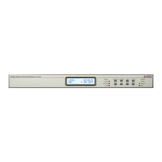
- Page 1 MODEL 1200B MODEL 1201B/C GNSS SYNCHRONIZED CLOCK OPERATION MANUAL ARBITER SYSTEMS, INC. PASO ROBLES, CA 93446 U.S.A. WWW.ARBITER.COM...
- Page 2 Description This manual describes the operation and configuration of the Model 1200B and Model 1201B/C GNSS Synchronized Clocks. It is issued for reference only, at the convenience of Arbiter Systems. Reasonable effort was made to verify that all contents were accurate at publication.
- Page 3 The responsibility of Arbiter Systems under this warranty is limited to repair or replacement, at Arbiter Systems’ option, of any product found to be defective. Arbiter Systems shall have no liability under this warranty unless it receives written notice of any claimed defect.
- Page 5 Using a Surge Arrester Appendix B Options List Appendix C Self-Signed Certificate for HTTPS Appendix D CE Mark Certification Appendix E Statement of Compliance Index Copyright Arbiter Systems Incorporated January 2021 All rights reserved. International copyright secured. Publication number: PD0051300G Reorder number: AS0096700...
-
Page 6: Table Of Contents
1 Getting Started 1.1 Model 1200B and 1201B/C Common Features ..... . 1.2 Model 1201B/C Advantages ....... . - Page 7 CONTENTS 4 GNSS Antenna and Cable Information 4.1 GNSS Antenna Installation ....... . 11 4.1.1 Mounting the Antenna .
- Page 8 viii CONTENTS 6.5.3 Holdover Estimated Uncertainty Model 1201B/C Only ... . . 28 6.5.4 Event/Deviation ........28 6.6 System Key Displays .
- Page 9 CONTENTS 8 Front Panel Menu System 8.1 Menu System ........55 8.1.1 Upper Keys .
- Page 10 CONTENTS 9.3.7 Protecting the 200 V FET Connection ..... . 78 9.3.8 DCF77 Time Signal ....... . 78 9.4 Connecting the Outputs .
- Page 11 CONTENTS 11.3 Custom Broadcast String Reference ......102 11.3.1 Installing a Custom String ......102 11.3.2 Start Custom Broadcast .
- Page 12 CONTENTS A Using a Surge Arrester A.1 Description ......... 115 A.2 Installation .
- Page 13 CONTENTS xiii B.10.2 Specifications ........139 B.10.3 Firmware Configuration .
- Page 14 2.2 Keypad and Annunciator LEDs (LEARN is labeled SURVEY on the 1200B) ..2.3 Model 1200B and Model 1201B/C Rear Panel Description ....
- Page 15 LIST OF FIGURES 7.16 Programmable Pulse, Single Trigger Screen ..... . . 46 7.17 Miscellaneous Screen ........48 7.18 Option Board Configuration Screen .
- Page 16 LIST OF FIGURES B.8 Startup Page ........149 B.9 System Configure Page .
- Page 17 List of Tables 3.1 Fuse Chart ......... 4.1 Antenna Mounting Bracket Parts List .
- Page 18 xviii LIST OF TABLES 11.9 Short Table of ASCII Characters ......107 12.1 Relay Specifications .
-
Page 19: Getting Started
1201B/C can provide the highest level of timing stability in the presence of a false GNSS signal, or from losing the GNSS reception. The Model 1201B/C is more accurate at 100 ns whereas the Model 1200B accuracy is 200 ns. The Model 1201B/C also benefits from the addition of ultra-stable oscillators with guaranteed holdover capability. -
Page 20: Standard Accessories
Getting Started Standard Accessories Components and accessories shipped with the clock are listed below. A pdf version of the operation manual may be downloaded from the Arbiter website. ˆ GNSS Synchronized Clock ˆ Choice of internal power supply ˆ Antenna Cable, 15 m (50 ft) with connectors ˆ... -
Page 21: Removing Rackmount Ears
1.6 Removing Rackmount Ears Removing Rackmount Ears Each clock comes with two, pre-installed rack-mount ears suitable for mounting in a 19 inch rack system. These ears have four mounting holes, two used to attach the rack-mount ear to one side of the clock, and two that attach the clock to the rack-mount system. -
Page 22: Front And Rear Panels
This section identifies the connectors, controls, and displays found on the front and rear panels of the 1200B and 1201B/C series clocks. Take care to review all of these items prior to connecting any cables and wires, and configuring the clock. -
Page 23: Command Key Definitions
POWER B UNLOCKED ALARM FAULT Figure 2.2: Keypad and Annunciator LEDs (LEARN is labeled SURVEY on the 1200B) ˆ : Press to change the display(s) to the desired mode. There are four modes available TIME/DATE and repeatedly pressing this key will scroll through all modes. Changing the time display does not effect time data of the rear-panel timing outputs. -
Page 24: Lcd Display
2.2.3 LCD Display The Model 1200B, Model 1201B and Model 1201C all have an LED backlit liquid crystal display (LCD), which provides a 20-character by 2-line readout. The readout displays instrument status, time, date, and event data. If configured to do so, the readout may also display the current configuration of operating parameters. -
Page 25: Connecting Inlet Power, Input And Output Signals
Chapter 3 Connecting Inlet Power, Input and Output Signals Instructions in this chapter include making connections to the rear panel of the clock. Carefully examine the labels to verify the inlet connections and voltages. It is possible to have two different inlet voltage ranges. -
Page 26: Low Dc, Power Supply Inlet
Connecting Inlet Power, Input and Output Signals Low DC, Power Supply Inlet The low DC supply accepts 22 Vdc to 67 Vdc ONLY (< 30 VA typical) and uses the same three- terminal inlet connector as the Universal High Voltage Supply. This power supply inlet can be located in a position labeled on the rear panel. -
Page 27: Antenna Input
3.4 Antenna Input CAUTION: Replace fuse only with another of the same type and rating. See Table 3.1 above for the correct fuse configured for your power supply option. Antenna Input Figure 3.3 illustrates the female Type F, GNSS antenna input, connector. This connector also supplies 5 Vdc through the cable to energize the antenna and inline preamplifier if installed. -
Page 28: Standard Inputs/Outputs
Connecting Inlet Power, Input and Output Signals RELAY Figure 3.5: Relay Contacts Connector (NC NO COM) Standard Inputs/Outputs Figure 3.6 illustrates the timing input/output connectors available for multiple purposes including modulated IRIG-B, unmodulated IRIG-B, 1 PPS, programmable pulse, open drain pull down, and event input. -
Page 29: Gnss Antenna And Cable Information
fixture. The piece of pipe nipple should be threaded up into the antenna receptacle after connecting the antenna cable to the Type F cable adapter. Arbiter Systems sells an antenna mounting kit that simplifies installation for a variety of locations. Figures 4.1, 4.2... -
Page 30: Optional Antenna Mounting Bracket
The antenna bracket can be mounted to a wall, a roof, or any other flat surface using the correct hardware. For complete details on this product, request Installation Instructions for Arbiter Systems GNSS Antenna Mounting Bracket. All metallic hardware is stainless steel. -
Page 31: Antenna Mounting Bracket
4.1 GNSS Antenna Installation Figure 4.2: Antenna Mounting Bracket Figure 4.3: Antenna with Mounting Kit... -
Page 32: Verifying Antenna And Cable Operation
GNSS Antenna and Cable Information Verifying Antenna and Cable Operation A multi-color LED, located at the base of the antenna, indicates antenna operation; green indicates proper operation (i.e. the antenna is getting the correct voltage), amber indicates that the voltage is low. -
Page 33: Gnss Surge Arrester
4.3 GNSS Surge Arrester GNSS Surge Arrester The clock has an internal surge arrester to protect the GNSS receiver from voltage spikes. It uses a gas discharge tube and high voltage capacitors. Arbiter also sells an external surge arrester for additional protection. Figure 4.4 illustrates the GNSS surge arrester kit, which is mounted in line with the antenna cable. -
Page 34: Gnss Cable Data And Accessory Information
The delay for a standard, 15-meter RG-6 cable is 60 nanoseconds. For other cable assemblies supplied by Arbiter Systems, the delay is tabulated in Table 4.2 below. For cable assemblies not found in Table 4.2, use Equation 4.1 for calculating cable delay. For other lengths and types of cables, remember to add 40 ns to your cable delay and enter that value into the clock. - Page 35 4.4 Technical Details of GNSS Antennas and Cables Physical Protection When routing the antenna cable, protect it from physical damage, which may result from closing doors, falling objects, foot traffic, etc. Also, when routing around corners, allow for sufficient bend radius to prevent kinks.
-
Page 36: Setting Internal Jumpers
Chapter 5 Setting Internal Jumpers Jumpers in the clock are shipped in the factory default position , or according to the purchase order notes. Should it be necessary to change any jumpers or to enable an alternate function, follow the instructions in this chapter. -
Page 37: Main Board And Jumper Locations
5.2 Setting Mainboard Jumpers PORT 3 PORT 2 PORT 1 COM1 COM2 U29 FIBER OPTIC PORT - OPTIONAL R24 IS USER SUPPLIED JMP9 JMP12 JMP7 ANTENNA JMP11 PORT 3 PORT 2 PORT 1 CONNECTOR SOURCE SOURCE SOURCE SELECT SELECT SELECT PORT 4 RELAY CURRENT LIMITING... -
Page 38: Digital Outputs: Port 1, Port 2 And Port 3
Setting Internal Jumpers I/O PORT 1 I/O PORT 2 I/O PORT 3 FIBER RS-485 RELAY Drive Type JMP7 JMP12 JMP9 CMOS OPEN DRAIN EVENT IN Signal Select JMP6 JMP12 JMP13 JMP8 JMP14 JMP2 JMP10 IRIG-B Modulated IRIG-B Unmodulated 1 PPS Programmable Pulse Data Out... -
Page 39: Programmable Pulse, 5 V Outputs
5.2 Setting Mainboard Jumpers 5.2.4 Programmable Pulse, 5 V Outputs A 5 V programmable pulse signal is available with the following jumper configuration. T T L Port Number Required Jumper Positions JMP6 = B and JMP7 = A JMP13 = B and JMP12 = A JMP8 = B and JMP9 = A Table 5.4: Programmable Pulse Jumper Table 5.2.5... -
Page 40: Fiber Optic Output: Optional
Setting Internal Jumpers Relay Function Required Jumper Positions Out of Lock, fault, alarm, stabilized JMP10 = A Programmable Pulse JMP10 = B Direct COM Connection JMP11 in and no resistor Resistive COM connection JMP11 out and resistor mounted Table 5.7: SPDT Relay Jumper Table 5.2.8 Fiber Optic Output: Optional Optionally, one 820 nanometer fiber optic output with type ST connector is available for... -
Page 41: Startup And Operation
NORMAL LED will illuminate. 6.1.1 Display Indication at Startup When power is applied, the LCD should indicate as follows: ARBITER SYSTEMS GNSS ARBITER SYSTEMS GNSS MODEL 1201B/C CLOCK MODEL 1200B CLOCK COPYRIGHT (C) 2020 ARBITER SYSTEMS, INC. TIME NOT AVAILABLE... -
Page 42: Clock Time, Startup Mode
Startup and Operation 6.1.2 Clock Time, Startup Mode When the clock first starts, it will not indicate the correct time until it is locked to the GNSS. Pressing the key before the UNLOCKED LED is extinguished will produce the message: TIME/DATE TIME NOT AVAILABLE IRIG-B time and the LCD display will not produce a time while the clock is starting up. -
Page 43: Time/Date Key Displays
6.3 Time/Date Key Displays longer detected. Further definition of the faults and alarms are defined in Table 6.1, and may be declared on the front panel and from the web interface. See details in Section 6.6.4 for fault display indications. Faults Alarms Time Base Processor (TBP) communication... -
Page 44: Antenna Key Displays
Startup and Operation Antenna Key Displays Press the key a few times to move between screens related to antenna performance, ANTENNA GNSS tracking, as well as the antenna’s geographical position. 6.4.1 GNSS Tracking To view the number of satellites being tracked, use this display. GNSS receivers can track up to 32 satellites of the multiple satellite systems. -
Page 45: Timing Key Displays
6.5 Timing Key Displays Synchronization to a minimum of four satellites is necessary for precise determination of longitude, latitude, and elevation. When meeting this minimum satellite lock requirement, its position will accurately correspond to the present antenna location. Longitude Display Displays the antenna longitude in degrees, minutes, seconds and fractional seconds, East or West. -
Page 46: Holdover Estimated Uncertainty Model 1201B/C Only
Startup and Operation 6.5.3 Holdover Estimated Uncertainty Model 1201B/C Only “Time Quality” is a 2.0 sigma (σ) estimate based on time-base processor measurements. This is basically saying that there is a 95% confidence factor that the clock will be within the estimate given (e.g. -
Page 47: System Key Displays
6.6 System Key Displays Deviation Display If DEVIATION is selected, press the TIMING key until reaching EVENT/DEVIATION, then press ENTER. Values are continuously updated each second (dashes show no input): --- µ S 1 PPS: --- µ S SIGMA: System Key Displays Press the key to review the clock identity and systems that support accurate and stable SYSTEM... - Page 48 Startup and Operation FAULT: TBP COM ERROR dd/mm/yyyy hh:mm:ss An error in communication exists between the TBP and the main processor. The fault disappears if communication is reestablished. Second line is the time the fault occurred. FAULT: VCXO FAIL dd/mm/yyyy hh:mm:ss The 8 MHz, Holdover Oscillator, signal is not getting to the main processor.
-
Page 49: Utility Software
Service/Support menu. Scroll down to Timing Software and select Model 1201B/C Software or Model 1200B Software. Download the Utility to your computer. Double click the icon and in a few moments the program should start as illustrated in Figure 7.1. -
Page 50: Installing The Utility
Utility Software 7.2.2 Installing the Utility The Utility does not need to be installed as most programs require. Instead you can copy the executable file to your computer and run it by double clicking on the program icon. Alternatively, you can make a shortcut to the program. 7.2.3 How the Utility Software Works The Utility allows you to read, write (configure) and verify operation on the clock. -
Page 51: Security
7.3 Security Security One of the goals of these security features is to help in complying with NERC CIP requirements. The clock security is flexible, allowing multiple levels of access. The clock may be queried and configured using the Utility, which uses a proprietary binary protocol allowing access through a custom user interface. -
Page 52: Establishing A Serial Connection
Utility Software Establishing a Serial Connection NOTE: A null-modem cable is needed to connect with the clock to the computer’s serial port. Pin connections and functions are as follows: PC side – Clock side 3, TxD – 2, RxD 2, RxD –... -
Page 53: Reading The Clock Configuration
7.5 Reading the Clock Configuration Reading the Clock Configuration When first starting the Utility there will be two functions available: allows Open Read Read you to poll the connected clock and download all of the configured information. You can find by either by selecting >... -
Page 54: Starting The Learn Mode
Utility Software Starting the Learn Mode Initially, the very first time that the clock starts up, it will be in the Promiscuous Mode. While in this mode, the clock is not protected against GNSS spoofing, clock movement and other things that would disturb its operation. -
Page 55: The Status Screen
7.7 The Status Screen The Status Screen After selecting , or clicking the icon, the Utility will display the first tab Device > Read Read information labeled . Status is organized in three groups: (1) clock status, (2) power supply Status status, and (3) antenna status. -
Page 56: The Performance Screen
Utility Software The Performance Screen The performance screen gives a glimpse at how the clock is performing with regard to run time, time quality and estimated holdover uncertainty. Run Time includes the number of power cycles, previous run time (before the last power cycle), current run time and total run time. Time quality is a 2σ... -
Page 57: The Fault Screen
7.9 The Fault Screen The Fault Screen The fault screen provides some control over the behavior of the fault reporting and recording system on the clock. The Clear box will remove the specific fault record from memory and the reported fault from the status display. -
Page 58: The Version Screen
Utility Software 7.10 The Version Screen Choose the Version tab to view the clock serial number and firmware version, which is defined by the release date. Figure 7.8: Version Display Screen... -
Page 59: Com1 & Com2 - Communication Screens
7.11 COM1 & COM2 – Communication Screens 7.11 COM1 & COM2 – Communication Screens are two separate communication ports, which are set up independently and COM1 COM2 accessible from separate tabs. This section will cover the setup of COM1. COM2 is set up similarly and the setup screen looks identical except for the title. -
Page 60: The Time Screen
Utility Software 7.12 The Time Screen Select the tab to set up your local offset, and daylight saving time (DST) preferences. Local Time offset should not change, and is the difference between UTC and your local standard time. For example, Pacific Standard Time is -8 hours, and Singapore is +8 hours. H1owever, DST advances the time by one hour, and removes the hour advance each year. -
Page 61: The Outputs Screen
7.13 The Outputs Screen 7.13 The Outputs Screen The Outputs screen provides for the setup of three groups of output functions: (1) the IRIG-B time code settings, (2) the programmable pulse settings, and (3) the relay operation. 7.13.1 Standard IRIG-B Section Two settings in the section set up: (1) the time zone, and (2) the C37.118.1 setting. -
Page 62: Auxiliary Irig-B Mode
Utility Software Auxiliary IRIG-B: This is a completely independent instance of IRIG-B. Select as Mode IRIG-B and go to IRIG-B tab to set up auxiliary time zone and IEEE C37.118.1 setting. Polarity: Pulses may be set to transition positively or negatively. Single Trigger: Specify the time and date, UTC or Local, for a pulse event. -
Page 63: Seconds Per Pulse Mode
7.13 The Outputs Screen 7.13.3 Seconds Per Pulse Mode Choose this programmable pulse mode to provide a pulse every X number of seconds, where X can be from 1 to 60,000 seconds. After configuring the pulse mode, make sure to change the jumper for the chosen port to programmable pulse. -
Page 64: Pulse Per Day Mode
Utility Software 7.13.5 Pulse Per Day Mode Choose this programmable pulse mode to provide a pulse every day at the chosen hour, minute, second and fractional seconds. Configure the pulse width, from 10 milliseconds to 600 seconds. Check jumpers in Table 5.1. Figure 7.15: Programmable Pulse, Pulse Per Day Screen 7.13.6 Single Trigger Mode... -
Page 65: Slow Code
7.13 The Outputs Screen 7.13.7 Slow Code Selecting slow code causes the output to be held high and go LO for two seconds on the minute, four seconds on the hour and six seconds on the day. 7.13.8 DCF77 and DCF77 Modified The DCF77 is a German longwave time signal and standard-frequency radio station. -
Page 66: Miscellaneous Screen
Utility Software 7.14 Miscellaneous Screen Figure 7.17 illustrates the screen where there are a few less frequently configured items, Misc including: Antenna Power, System Delay, LCD Backlight (ON, OFF, Auto), C-Display Format, Event Input settings and Out of Lock Detection. Figure 7.17: Miscellaneous Screen 7.14.1 Miscellaneous Items... -
Page 67: Option Screen
7.15 Option Screen 7.15 Option Screen Figure 7.18 illustrates the Option Screen, which allows the configuration of a specific installed option board. By configuring the correct option by name here, the clock will recognize what is installed and provide any needed information to the relevant clock function(s). When some options are selected, like the Time and Frequency Monitor, other settings not shown in Figure 7.18 will appear. -
Page 68: Security Screen
Utility Software 7.16 Security Screen You can access three functions from the Security screen: Security levels, Password control and Spoofing. Figure 7.19 illustrates the security screen. Under Security you can set up to control specific access points. There are six levels of security (0, 1, . . . , 5) that provide various levels of operation from the front panel keyboard and display, and restrict the RS232 ports access. -
Page 69: Uploading A Configuration
7.17 Uploading a Configuration and should not be changed. This value has been chosen to provide an extremely low likelihood of false detection, while having very high sensitivity to a real attack. Enable Re-Locking If disabled (unchecked) the clock will never attempt to recover from a spoofing detection. Normally, if ”Enable Re-locking”... -
Page 70: Clearing Events In The Clock
Utility Software Clearing the Event Buffer To clear all events stored in the event buffer, select . See Figure 7.21. Device > Events > Clear Events While broadcasting event records, the buffer will continually be overwritten with new data. Therefore, you would not need to use the feature while broadcasting event data. -
Page 71: Uploading New Firmware
Before starting the upload process, there are a few things to have prepared ahead of time. Obtain the new firmware from Arbiter Systems. Make sure that the clock and the computer are powered by an uninterruptable power source. Lastly, test the serial connection by performing a Device >... -
Page 72: Setting To Factory Defaults
Utility Software 7.19 Setting to Factory Defaults At some time it may be necessary to reset the clock to its original firmware configuration when it left the factory. This is called “resetting to factory defaults” and requires disabling security. Resetting the clock to factory defaults clears memory including any information that may cause problems with its operation. -
Page 73: Front Panel Menu System
Chapter 8 Front Panel Menu System This chapter covers the operation of the clock using the front panel display and keypad. Menu System Since the front panel operation is based on specific security levels, verify the security level as enumerated in Section 7.3. Only the lowest level – Level 0 – allows a user to configure the clock from the front panel. -
Page 74: Lower Keys
Front Panel Menu System 8.1.2 Lower Keys To start configuring using the keypad, press SETUP as illustrated in Figure 8.1. Accessing the clock configuration menus depends on your clock’s security settings. For reference, individual setup menus are listed in Table 8.2, and in greater detail throughout this chapter. 8.1.3 Configure Using the Keypad Figure 8.1 illustrates the clock keypad and annunciator LEDs, with Table 8.2 listing the various... -
Page 75: The Setup Menus
8.1 Menu System 8.1.4 The Setup Menus Setup Menus Setup Items Set Serial COM 1? Main RS-232 port parameters and broadcast Set Serial COM 2? Second RS-232 port parameters and broadcast Set Local Time? Set local offset, daylight saving mode Set Out-Of-Lock? Set out-of-lock mode, and time interval before alarm occurs Set Relay Config.? -
Page 76: Numeric Data Entry Mode
Front Panel Menu System The figure below illustrates two elements of the setup menu flow chart: a larger rounded rectangle and a small oval. The larger rounded rectangles represent messages within the clock LCD display, and the small oval symbol represents the individual keys of the eight-button keypad. DISPLAY MENU 8.1.7 Numeric Data Entry Mode... -
Page 77: Serial Com Port Settings
8.2 Serial COM Port Settings Serial COM Port Settings Press SETUP to enter the configuration menus. 8.2.1 Serial COM 1 Use the “SET SERIAL COM 1” menu (See Figure 8.2) to configure RS232 settings and to broadcast data. To configure COM 1 port parameters press ENTER, then UP or DOWN to choose the desired value. -
Page 78: Setting The Local Time
Front Panel Menu System Setting the Local Time Use the “SET LOCAL TIME?” menu to configure the local offset from UTC to your local standard time, and add any Daylight Saving settings if they apply. Offsets may be adjusted in 15-minute increments, up to plus or minus 12 hours. -
Page 79: Auto Daylight Saving Setup
8.3 Setting the Local Time For RS-232 command, see Section 11.2.6. AUTO DST/SUMMER TIME ENTER SETUP AUTO DOWN OFF* START DAY ENTER DOWN SUN* +0720 START MINUTE ENTER +0120* 0120 DOWN -0720 START MONTH ENTER MAR* DOWN 3rd from Last START WEEK 2nd from Last ENTER... -
Page 80: Setting Out Of Lock Indication
Front Panel Menu System Setting Out of Lock Indication Use the “SET OUT OF LOCK?” menu to control how the clock responds to an out-of-lock condition. Out of lock means that the GNSS receiver in the clock is no longer tracking any satellites and that the time may drift according to characteristics of the internal holdover oscillator and environmental conditions. -
Page 81: Set Mulitpurpose Relay Configuration
8.5 Set Mulitpurpose Relay Configuration Set Mulitpurpose Relay Configuration Use the “SET RELAY CONFIG?” menu to configure how the multipurpose relay responds to several clock conditions. Clock conditions include (1) out of lock, (2) faults, (3) alarms, (4) stabilization, and (5) failsafe. These are described in the setup procedure shown in Figure 8.6. Alarms consist of any outside influence, such as a sudden change in GNSS position , that may affect the operation of the clock. -
Page 82: Setting The Back Light
Front Panel Menu System Setting the Back Light Use the “SET BACK LIGHT?” menu to configure how the back light operates. Settings are either BACK LIGHT OFF, BACK LIGHT ON, or BACK LIGHT AUTO. In the Auto setting, the back light will operate for approximately 30 seconds before switching off. -
Page 83: Setting Programmable Pulse Mode
8.8 Setting Programmable Pulse Mode Setting Programmable Pulse Mode Use the “SET PROG. PULSE?” menu to set up one of the many pulse modes, in which you can broadcast over one of the standard outputs (Port1, Port2, or Port3) at a predetermined interval or rate. -
Page 84: Programmable Pulse: Seconds-Per-Pulse Mode
Front Panel Menu System 8.8.2 Programmable Pulse: Seconds-Per-Pulse Mode Use the “SEC. PER PULSE?” mode to generate a pulse every X number of seconds, from 1 to 60,000 seconds (16+ hours), and a Pulse Width of from 10 milliseconds to 600 seconds. Pulse Polarity marked (+) starts at a logic low and transitions high. -
Page 85: Programmable Pulse: Pulse-Per-Hour Mode
8.8 Setting Programmable Pulse Mode 8.8.3 Programmable Pulse: Pulse-Per-Hour Mode Use the “PULSE PER HOUR?” mode to generate a pulse every hour, at the number of specified seconds (from 0 to 3599 seconds) after the hour. Configure as illustrated in Figure 8.11. Refer to Section 8.8 above for additional detail on the programmable pulse modes, and entering numerical values. -
Page 86: Programmable Pulse: Pulse-Per-Day Mode
Front Panel Menu System 8.8.4 Programmable Pulse: Pulse-Per-Day Mode Use the “PULSE PER DAY?” mode to generate a pulse every day, at the specified hour, minute, second and fractional seconds. Configure as illustrated in Figure 8.12. Refer to Section 8.8 above for additional detail on the Programmable Pulse mode, and entering numerical values. -
Page 87: Auxiliary Irig-B
8.8 Setting Programmable Pulse Mode 8.8.5 Auxiliary IRIG-B Use the “SET PROG. PULSE?” menu to setup a second instance of IRIG-B that may have another time zone and IEEE C37.118.1 setting than the “SET IRIG TIME DATA” menu. When you use this mode, regular programmable pulse features are disabled. -
Page 88: Programmable Pulse: Single Trigger
Front Panel Menu System 8.8.6 Programmable Pulse: Single Trigger Use the “SINGLE TRIGGER?” mode to generate a transition once per year at the specified Julian Day, hour, minute, second and fractional seconds. For reference, many calendars indicate the Julian Day. A single trigger will transition from 0 Vdc to 5 Vdc when the Pulse Polarity is set to positive, or from 5 Vdc to 0 Vdc if the Pulse Polarity is set to negative. -
Page 89: Programmable Pulse: Slow Code
8.8 Setting Programmable Pulse Mode 8.8.7 Programmable Pulse: Slow Code Use the “SLOW CODE UTC?”, or “SLOW CODE LCL?” mode to cause the output voltage to be held high and go low for six seconds on the day, four seconds on the hour and two seconds on the minute. -
Page 90: Setting Irig Time Data
Front Panel Menu System Setting IRIG Time Data Use the “SET IRIG TIME DATA?” menu to adjust the time zone from UTC to Local, and to turn the IEEE C37.118.1 extension ON or OFF for outgoing IRIG-B time code. Turning the IEEE C37.118.1 control bits ON includes some additional information (see Section 9.3.3) contained in the IRIG-B time code. -
Page 91: Setting Option Control
8.11 Setting Option Control 8.11 Setting Option Control Use the “SET OPTION CONTROL?” menu to configure any auxiliary board option if mounted in the clock. Some of these options require you to configure additional settings. For information on configuring specific options see the Option List located in Appendix B. For RS-232 command, see Section 11.2.13. -
Page 92: Timing, Irig-B And Pulses
Timing Output Description The rear panels of the Model 1200B, Model 1201B, and Model 1201C are identical, and you will see a number of different types of connectors as illustrated in Figure 9.1. There are three standard timing output connectors, labeled I/O PORTS (1, 2, and 3), where you can connect cables for timing. -
Page 93: Inputs And Outputs: Port 1, Port 2, Port 3
9.2 Timing Output Description RELAY COM2 I/O PORTS COM1 FIBER ANTENNA POWER B POWER A Serial Number INTERNAL OPTION SPACE ANTENNA STATUS Made in USA Figure 9.1: Rear Panel Descriptions, optional outputs may be shown 9.2.1 Inputs and Outputs: Port 1, Port 2, Port 3 Three, Phoenix-style, terminal connectors supply timing signals to external equipment and may also be configured for an event input. -
Page 94: Output Signal Description
Timing, IRIG-B and Pulses Output Signal Description Both clock models can provide three different digital signals and one analog signal. Digital signals consist of unmodulated IRIG-B, 1 PPS and Programmable Pulse. Analog consists of modulated IRIG-B. 1 PPS is often used to synchronize another (unsynchronized) timing signal. Programmable pulse modes are similar to 1 PPS only they have an adjustable period and pulse width with an on-time rising edge. -
Page 95: Irig-B Ieee C37.118.1
9.3 Output Signal Description ON-TIME 1 PPS Start of next second in time code Unmodulated Reference Reference IRIG ZERO IRIG ONE Modulated Figure 9.2: IRIG-B Waveforms 9.3.3 IRIG-B IEEE C37.118.1 As mentioned above, turning IEEE C37.118.1 ON in the clock enables extra bits of the Control Function (CF) portion of the IRIG-B time code. -
Page 96: Programmable Pulse (Prog Pulse)
Timing, IRIG-B and Pulses 9.3.5 Programmable Pulse (PROG PULSE) The clock has a programmable pulse feature that may require some jumper and firmware configuration. There are a number of available programmable pulse modes from which to choose – see list below – that include setting the pulse width and time zone. For jumper configuration, please see Section 5.2.4. -
Page 97: Connecting The Outputs
9.4 Connecting the Outputs Year Information content provided by third parties Month Day of the week Calendar Minute Hour Figure 9.3: DCF77 Timing Diagram – see Marker Details DCF77 Marker Details minute marker (second marker No. 0): 0.1 s second marker No. 15 indicates service request to the DCF77 signal generation system announcement of a forthcoming change from CET to CEST or vice versa Z1, Z2 time zone indication: CET: Z1, 0.1 s, Z2 0.2 s;... -
Page 98: Attaching Cables To Screw Terminals
Timing, IRIG-B and Pulses 9.4.1 Attaching Cables to Screw Terminals Strip the insulation back to expose about 6 mm (1/4 in) of bare wire. DO NOT tin with solder. Insert the stripped wire into the terminal and tighten the set screws clockwise to secure. 9.4.2 How Far Can I Run IRIG-B Cabling? Factors to consider for long digital-signal cable runs: (1) resistive losses, (2) electromagnetic interference,... -
Page 99: Connecting Modulated Irig-B
9.4 Connecting the Outputs 9.4.5 Connecting Modulated IRIG-B While the modulated driver supplies approximately 4.5 volts peak-to-peak (Vpp) open circuit, it can supply 3 Vpp into 50 Ω. This amounts to about 0.06 A (60 mA) drive current. Make sure to check the acceptable voltage range for the equipment. Some modulated IRIG-B decoders are fairly sensitive to peak-to-peak voltage levels (3.3 Vpp 0.5 Vpp), others are more tolerant (0.1 Vpp to 10 Vpp). -
Page 100: Cable Delays
(VF), which is a percentage of the speed of light in free space, and characteristic of the specific cable. The Velocity Factor for the RG-6 cabling used by Arbiter Systems for GNSS antenna connections, is about 83 % of C. Most transmission lines have velocity factors in the range of 65 % to 97%. -
Page 101: Relay Contacts And Event Inputs
Chapter 10 Relay Contacts and Event Inputs 10.1 Relay Contacts 10.1.1 Introduction One single set of mechanical SPDT relay contacts are available. There are two possible relay choices: Standard Voltage and High DC-Voltage. 10.1.2 Relay Operation The relay may be configured for programmable pulse or one of these clock conditions: (1) out-of-lock, (2) fault, (3) alarm , (4) stabilized, and (5) failsafe, indicating loss of inlet power. -
Page 102: High Dc-Voltage Relay Ratings
Relay Contacts and Event Inputs 10.1.4 High DC-Voltage Relay Ratings Specification Value Arrangement 1 set of Form C (SPDT) contacts Operate, release time Approx. 10 ms, 5 ms Rated voltage 250 Vac (300 Vdc) Max switching voltage 400 Vac (300 Vdc) Rated switching cur- 8 A at 250 Vac, 8 A at 30 Vdc rent (resistive) -
Page 103: Pps Deviation Measurement Principle
10.2 Event and 1 PPS Deviation Recording 10.2.4 1 PPS Deviation Measurement Principle The measurement technique employed for 1 PPS Deviation uses the same time determination and recording scheme used for event time measurement (refer to paragraph above), but makes the assumption that the input signal is periodic and continuous. -
Page 104: Pps Deviation
Relay Contacts and Event Inputs 10.2.8 1 PPS Deviation If the event capture channel is configured for 1 PPS Deviation (via Event/Deviation Setup Menu), the readout will display the deviation of the 1 PPS input signal. In this case, the readout display will have the format: A 1 PPS XXXXX.XX µS SIGMA: XXXXX.XX µS... -
Page 105: Rs-232C Command Set
Chapter 11 RS-232C Command Set 11.1 Introduction This chapter provides information on using simple serial commands through either COM1 or COM2 instead of the Utility software. Set security to Level 0 to be able to use all of these commands. Set security to Level 1 if you only want to start or stop broadcasting. -
Page 106: Installing Custom Broadcast Strings
Data is transmitted ahead of time and the BEL character is transmitted on time. The Vorne displays update simultaneously upon receipt of the BEL character. Refer to Arbiter Systems Application Note 103 for more information on using large format displays. -
Page 107: Status Indications And Definitions
11.2 Standard Command Set Broadcast Mode: EVENT DATA Command: B3, O3 Starts the event data broadcast. Outputs when an event is recorded. B3 = COM1. O3 = COM2. Response: mm/dd/yyyy hh:mm:ss.sssssss nnnAt<CR><LF> Where: = month = day yyyy = year = hour = minute ss.sssssss = second... - Page 108 RS-232C Command Set Broadcast Mode: EXT. ASCII Command: B5, O5 Starts the time-of-day broadcast using an extended format prefaced with a time quality indicator (Q). B5 = COM1. O5 = COM2. The start bit of a carriage-return is transmitted on time. Response: <CR><LF>Q yy ddd hh:mm:ss.000 Where: <CR>...
- Page 109 11.2 Standard Command Set Broadcast Mode: YEAR + ASCII Command: B8, O8 Starts time-of-day broadcast appended with year and time quality indicator. B8 = COM1. O8 = COM2. Response: <SOH>yyyy ddd:hh:mm:ssQ<CR><LF> Where: <SOH> = Hex 01 – the start bit of the SOH character is transmitted on time. = Julian day-of-year = hour = minute...
- Page 110 RS-232C Command Set Broadcast Data: ABB SPA MSG Command: 0,nTB Starts the ABB SPA broadcast from the COM port that received the request. Format: n = time format: 0 = UTC, 1 = local Response: >900WD:yy-mm-dd hh:mm:ss.fff:cc<CR> Where: >900WD: = beginning of string = year of century, (00.
-
Page 111: Event Mode Commands
11.2 Standard Command Set 11.2.3 Event Mode Commands Return Specific Event Command: nnA Sets the event buffer read index to a specific event number (01 to 50), and returns that event information in either Local or UTC time format depending on how the command, nTA is configured. Response: mm/dd/yyyy hh:mm:ss.sssssss nnAz<CR><LF>... -
Page 112: Status Mode Commands
RS-232C Command Set Return Single Event Command: EA Returns a single event record from the channel A event buffer. The record number (nn) increments once for every issuance of this command. Response: mm/dd/yyyy hh:mm:ss.sssssss nnAz<CR><LF> Where: = month = day of month yyyy = year = hour... -
Page 113: Unlocked Time Quality
11.2 Standard Command Set EEPROM Status Command: SE Returns the EEPROM status. Response: T=t CE=ee<CR><LF> Where: = 0, No Timeout Error; t = 1, Timeout Error = Number of corrected errors in reading EEPROM data <CR> = Carriage Return = Hex 0D <LF>... -
Page 114: System Log Messages
Command: 1201DX Clears all of the system messages stored in the Model 1201B/C memory. Command: 1200DX Clears all of the system messages stored in the Model 1200B memory. 11.2.6 Local / Daylight Saving Time Setup Commands Return Daylight Saving/Summer Time Settings Command: 0DT Returns the current Daylight Saving / Summer Time settings to the connected RS-232 port. -
Page 115: Front Panel Control Commands
11.2 Standard Command Set Set Daylight Saving/Summer Auto Start Time Command: 2,w,x,y,zDT Sets the starting (Start) date and time for Daylight Saving / Summer Time AUTO setting. Format: w = month (0 through 11), with 0 = Jan, 1 = Feb, ... 11 = Dec x = week of month (0 through 5), with 0 = First, 1 = Second, 2 = Third, 3 = Last, 4 = Second from Last, and 5 = Third from Last. -
Page 116: Irig-B Data Output Commands
RS-232C Command Set Set Backlight: (OFF, ON, AUTO) Command: Ln Format: n = mode: 0 = OFF, 1 = ON, 2 = AUTO Where: = disabled = continuously on AUTO = active for 30 seconds after last key press Response: <CR><LF> 11.2.8 IRIG-B Data Output Commands IRIG Data IEEE C37.118.1... -
Page 117: Date And Time Commands
11.2 Standard Command Set 11.2.9 Date and Time Commands Set Receiver Time Command: yyyy:MM:dd:hh:mmTS Sets the receiver to UTC time only available on initial power up and not locked to the GNSS. Format: yyyy = year MM = month = day = hour mm = minute Response: <CR><LF>... -
Page 118: Antenna System Delay Commands
RS-232C Command Set Seconds Per Pulse / Pulse Per Hour Command: m,nPS Configures the programmable pulse as “Seconds per Pulse” or “Pulse Per Hour” mode. Format: m = 0 seconds-per-pulse mode m = 1 pulse-per-hour mode n = 1 - 60000 seconds if seconds-per-pulse mode n = 0 - 3599 seconds offset from hour if pulse-per-hour mode Response: <CR><LF>... -
Page 119: Out-Of-Lock Commands
11.2 Standard Command Set 11.2.12 Out-of-Lock Commands Set Out-of-Lock Time Command: (-)nnK Configures the amount of delay time (in minutes) following loss of satellite synchronization before an out- of-lock signal is active. Format: nn = 0, zero delay nn = 1–99, 1 minute to 99 minutes nn = -1, any negative number disables out-of-lock Response: <CR><LF>... -
Page 120: Custom Broadcast String Reference
RS-232C Command Set Return IP/MAC Address: Development Command: IP Returns the IP and MAC addresses of both ports of the NTP/PTP Option. Dashes are used to show either an unassigned or unconnected port IP address. Sample response: NET1: 192.168.000.232 64:73:E2:00:00:23<CR><LF> NET2: ---.---.---.--- 64:73:E2:00:00:24<CR><LF>... -
Page 121: Constructing A Custom String
11.3 Custom Broadcast String Reference 11.3.4 Constructing a Custom String This section provides the character set and rules for constructing a custom string. At the end of this section is a tutorial on how to construct strings using some of the standard broadcast strings as examples. Custom Broadcast Character Set Character Meaning... -
Page 122: List Of Possible Time Quality Levels, Ordinal 01
RS-232C Command Set True/False Condition Command: /[ii? < t > / :< f > /] where: < t > = True condition < f > = False condition ii: 01 = Locked; 02 = Status change; 03 = Locked with max accuracy; 04 = Fault; 05 = Daylight Saving Time change pending;... -
Page 123: String Setup Examples And Tutorial
11.3 Custom Broadcast String Reference ordinals and conditionals when constructing a custom string. You can even construct standard strings to check your work. All the ordinal/conditional examples below use the ASCII Standard broadcast string. Ordinal 01. This ordinal consists of 13 different accuracy values as listed in Table 11.7. Notice the ordinals (0, 1, 2,...,B,F) are all represented in this example. - Page 124 RS-232C Command Set Vorne Standard Desired Output: 44hhmmss<CR><LF> 55ddd<CR><LF> 11nn<CR><LF> <BEL> Input String Code: 44/h/m/s/r55/d/r11/U/r/T07 Input String Construction Notes: Note that the ordinary method of starting the Vorne Standard broadcast is using the B2 or O2 command as described on page 88. This input string code begins with the characters “44”;...
-
Page 125: Short Table Of Ascii Characters
11.3 Custom Broadcast String Reference separated by a “/:” (OR), and (in this case) at last is a “/;” (ELSE). For ASCII + Qual, there are four OR conditions (specific time quality ranges) followed by one ELSE (worst quality range). The initial ordinal is a space, meaning maximum time quality followed by a “.”, a “*”, a “#”... -
Page 126: Technical Specifications And Operating Parameters
12.1.2 Processing The Model 1200B, Model 1201B, and Model 1201C both operate under the same principles and use the same basic components. Differences are: the Model 1200B does not have a holdover oscillator and only the 1201C has a large LED display in addition to the backlit LCD display. Supervision of these clock systems is under the control of several microprocessors dedicated to separate tasks. -
Page 127: Power Supply
Input Signal L1 GPS C/A, L1 GLONASS CT, Galileo, BeiDou 12.2.2 Timing Accuracy Specifications apply at the unmodulated IRIG-B, 1 PPS and Programmable Pulse outputs when receiving 4 or more satellites Model 1200B 200 ns peak Model 1201B/C 100 ns peak... -
Page 128: Position Accuracy (Rms)
Technical Specifications and Operating Parameters 12.2.3 Position Accuracy (rms) 2 meters, rms with SA (USA Department of Defense Selective Availability) OFF. 12.2.4 Satellite Tracking Seventy-two (72) channel receiver: GPS L1C/A, GLONASS L1OF, Galileo E1B/C, BeiDou B1 The receiver simultaneously tracks up to 72 satellites. 12.2.5 GNSS Acquisition Time ˆ... -
Page 129: System Interface
12.4 System Interface Relay Specification Type or Rating Arrangement 1 set of Form C (SPDT) contacts Contact resistance 100 mΩ Operate, release time Approx. 6 ms, 3 ms Rated switching current 8 A at 250 Vac, 5 A at 30 Vdc (resistive) Max. -
Page 130: Antenna System
ˆ C Display Format: Configures the date format for the large display on Model 1201C clocks to MM/DD/YY or DD.MM.YY. 12.6.3 Display ˆ Model 1200B and Model 1201B/C include a 2-line by 20-character LED backlit LCD ˆ Model 1201C also includes a six-character, 20mm LED time display... -
Page 131: Display Functions
84 mm (3.2 in 3.3 in) Table 12.5: Clock and Antenna Dimensions 12.7.2 Weight Model 1200B & Model 1201B Model 1201C 1.4 kg (3.0 lb) net. (Instrument) 1.9 kg (4.3 lbs) net. (Instrument) 2.0 kg (4.4 lb) net. (Antenna and Cable) 2.0 kg (4.4 lbs) net. -
Page 132: Temperature And Humidity
Operate Storage = 40 ° C to +65 ° C = 40 ° C to +75 ° C Model 1200B: = 40 ° C to +65 ° C = 40 ° C to +75 ° C Model 1201B/C: = 55 ° C to +65 ° C = 55 °... -
Page 133: A Using A Surge Arrester
Appendix A Using a Surge Arrester These instructions cover the installation of the Arbiter Systems Surge Arrester, as illustrated in Figure A.1. The surge arrester performs two basic functions: 1. Provides a solid and reliable grounding point for the antenna system connected to a GNSS receiver;... -
Page 134: Installation
Use the proper crimping tool if using crimp-on connectors. Improper tools may not guarantee a strong and sufficiently grounded connector resulting in poor cable performance and GNSS reception. Consider purchasing RF cables of various standard and custom lengths manufactured by Arbiter Systems. A.2.5 Suggested Mounting Figure A.2 illustrates the recommended mounting of the AS0094500 with the F-connectors facing downward. -
Page 135: Suggested Mounting Of The Gnss Surge Arrester
A.3 Physical Dimensions Figure A.2: Suggested Mounting of the GNSS Surge Arrester... -
Page 136: B Options List
While these options may apply to other clock models than the Model 1200B and the Model 1201B/C, the option reference numbers may be different for the other clock models. -
Page 137: Universal Inlet Power Supply
B.2 Universal Inlet Power Supply Universal Inlet Power Supply B.2.1 High Range Universal Supply with Terminal Power Strip, SWC This standard power inlet module uses a three-position, screw-type terminal block, and includes surge withstand capability (SWC). The terminal block is intended for use in installations where it is necessary or desirable to have the instrument power hard-wired. -
Page 138: Low Dc Inlet Power Supply
Options List Low DC Inlet Power Supply B.3.1 22 Vdc to 67 Vdc ONLY, Terminal Power Strip, SWC The Low DC power supply replaces the Universal power supply with a three-position, screw-type terminal block, including Surge Withstand Capability (SWC). With DC ONLY inlet voltages from 22 Vdc to 67 Vdc, this feature is intended for use in installations where it is necessary or desirable to have the instrument power hard-wired. -
Page 139: Holdover Oscillator (1201B/C Only)
B.4 Holdover Oscillator (1201B/C Only) Holdover Oscillator (1201B/C Only) C01: Holdover OCXO, 1 millisecond per day One Fiber Optic Output One, optional, fiber optic output is available with Type ST connector and 820 nm transmitter, compatible with multimode fiber. This output is configurable to any of the standard digital (CMOS) signal outputs available from the clock and provides an optical output power of -15 dBm minimum (-12 dBm typical) into 62.5/125 µ... -
Page 140: Jumper Configuration
Options List Jumper, Output Connector Correspondence Use jumper JMP1 and JMP9 for output J2, JMP2 and JMP10 for output J3, JMP3 and JMP11 for output J4 and JMP4 and JMP12 for output J5. Output Function, Output Mode & Clock Model To choose a specific signal for a specific output use jumpers described in Table B.1. -
Page 141: Four Configurable Outputs - Signal Choices
B. These are used for analog signals. In all other JMP1 – JMP4 positions (i.e. 3 – 20), JMP9 – JMP12 must be in position A for digital signals. Available signal choices in the Model 1200B and the Model 1201B/C are marked in Table B.1 with an asterisk (*). -
Page 142: Four Fiber Optic Outputs
– – IRIG-B Mod. Manch. 2, 3 Table B.2: Four Fiber Optic Output Configuration 1. Signals available on the Model 1093A/B/C, Model 1200B, and Model 1201B/C 2. Signals available on the Model 1088A/B 3. Signals available on the Model 1084A/B/C... -
Page 143: Jumper Locations
B.7 Four Fiber Optic Outputs Figure B.4: Jumper Locations... -
Page 144: 8-Channel High Drive Irig-B Amplifier
Options List 8-Channel High Drive IRIG-B Amplifier B.8.1 General Description This option provides eight independent, IRIG-B buffered outputs, each capable of driving multiple loads. Outputs are short circuit and surge protected. Each output is individually configurable for either modulated or unmodulated IRIG-B signals via jumper settings as illustrated in Figure B.5. B.8.2 Specifications Output Selection... -
Page 145: High Drive Outputs Jumper Locations
B.8 8-Channel High Drive IRIG-B Amplifier Figure B.5: 8 High Drive Outputs Jumper Locations... -
Page 146: Output Load And Loop Example: Unmodulated Irig-B
Options List B.8.4 Output Load and Loop Example: Unmodulated IRIG-B When designing circuits for connection to the output bus, several factors must be considered. 1. Loop Resistance 2. Type and quantity of loads connected 3. Maximum loop distance desired Table B.3 provides a matrix of these factors using the Schweitzer relay(s) as the output load(s). The loop distance figures were obtained using the following types of Belden Wire (cross-referenced to corresponding part number): AWG20... -
Page 147: Connecting Load(S) To Output Bus
B.8 8-Channel High Drive IRIG-B Amplifier B.8.5 Connecting Load(s) to Output Bus The following example illustrates use of different types of SEL relays connected to the output bus. Total Load Current: 250 mA (peak) per driver or less. Note 1: Shielding is optional. -
Page 148: Output Loading (Modulated Irig-B)
AGC amplifier, providing tolerance for signal level variations. Consequently, modulated IRIG- B loads may be connected with greater ease; Arbiter Systems recommends that you simply calculate the effective parallel load impedance of the parallel-connected loads. As long as the load impedance is 50 Ω or more per driver, and the loads will accept a 3 Vpp minimum signal level, and the connecting lines are short (5 Ω... -
Page 149: Power System Time, Frequency And Phase Monitor
B.9 Power System Time, Frequency and Phase Monitor Power System Time, Frequency and Phase Monitor B.9.1 General Description This section describes the optional Power System Time, Frequency, and Phase Monitor. B.9.2 Discussion Provides the clock with the ability to accept either a 50 Hz or 60 Hz, 30 Vrms to 300 Vrms signal input and measure the instantaneous phase, magnitude and frequency of the fundamental component while rejecting the effects of harmonics, noise and DC offsets. -
Page 150: Calibration
Options List TIME FREQUENCY 60 Hz Viewing the Measurements View the measurements on the front panel display as follows: 1. Press the SYSTEM key repeatedly until it states OPTION STATUS and press ENTER. Observe the following display on the front panel (values are representative): SYSTEM ∆... -
Page 151: Amplitude Calibration
1.0, and is multiplied by the measured result to generate the displayed value. If an accurate ac source at 50 Hz or 60 Hz is available (for example, the Arbiter Systems, Inc. Model 1040C Panel Meter Calibrator), the error can be measured and the correction factor entered as described. For example, if 120 Vrms is applied to the option assembly, and the display indicates 119.1 Vrms, the calibration factor is (120.0 / 119.1) or... - Page 152 Options List Return System Phase Command: PS PS returns the system phase. Response: SS ppp.pp<CR><LF> Where: SS = UTC seconds ppp.pp = phase, 0 to 360 degrees Return System Time Deviation Command: TD TD returns the system time deviation. Response: SS tt.tttt<CR><LF>...
-
Page 153: B2 Broadcast, Time Deviation Values
B2 configures COM1 to broadcast data to support Vorne large format time displays. Data is transmitted ahead of time, and the <BEL> character is transmitted on time. When properly configured, the Vorne display updates simultaneously upon receipt of the <BEL> character. Refer to Arbiter Systems Application Note 103 for more information. - Page 154 Options List B7 configures COM1 to broadcast Time, Frequency, and Phase Deviation, once per second, in ASCII format. O7 configures COM2 to broadcast Time, Frequency and Phase Deviation, once per second, in ASCII format. Response: broadcast mode, UTC: mm/dd/yyyy hh:mm:ssU ss +f.fff +t.tttt ppp.ppp vvv.vv<CR><LF> broadcast mode, Local: mm/dd/yyyy hh:mm:ssL ss +f.fff +t.tttt ppp.ppp vvv.vv<CR><LF>...
- Page 155 B.9 Power System Time, Frequency and Phase Monitor Period, decimal point Tenths, hundredths and thousandths of seconds ASCII F, indicates the start of Frequency Deviation Field Sign character + (2Bh) frequency above nominal or - (2Dh) frequency below nominal Units of Hertz (Frequency Deviation) Period, decimal point Tenths, hundredths and thousandths of Hertz <CR><LF>...
- Page 156 Options List hh:mm:ssU = Time of Day, UTC (or) hh:mm:ssL = Time of Day, Local = Status (0 = Locked, 1 = Unlocked) (first character is Reference Status:) (second character is clock status per IEEE C37.118.1) +f.fff signed Frequency Error in Hz. +t.tttt signed Time Deviation in seconds.
-
Page 157: Four Additional Outputs And Dry Contacts; +25/50 Vdc
B.10 Four Additional Outputs and Dry Contacts; +25/50 Vdc B.10 Four Additional Outputs and Dry Contacts; +25/50 Vdc B.10.1 General Description This section describes an optional board with the following features: Four Additional Outputs With Dry Contact and +25/50 Vdc. With six configurable outputs, this option includes four standard, 5 V CMOS outputs, two Aromat AQV210E solid-state relays (SSRs). - Page 158 Options List Solid State Relay Output, continued Output Power Supply: Individually configurable for 0 Vdc, +25 Vdc, or +50 Vdc. Available Output Sig- 1 PPS, Programmable Pulse, Locked and Out of Lock. nals: Pulse Width: Individually configurable for a fixed, 50 ms pulse, or the default width of pulse provided by the clock mainframe.
-
Page 159: Firmware Configuration
B.10 Four Additional Outputs and Dry Contacts; +25/50 Vdc Function Setup Jumpers: Default Settings 1 (Rightmost) CMOS Output 1 JMP4: Signal Select Default = 1 PPH Ground – CMOS Output 2 JMP3: Signal Select Default = 1 PPM Ground – CMOS Output 3 JMP2: Signal Select Default = Prog. -
Page 160: Output Jumper Setting Changes
Options List B.10.4 Output Jumper Setting Changes 1. Set the line power switch to OFF position (if equipped). Disconnect the power cord from rear panel. 2. Remove rack-ears (if equipped) and remove top cover using a T25 Torx driver (4 screws). 3. -
Page 161: Option Connector Signal Locations
B.10 Four Additional Outputs and Dry Contacts; +25/50 Vdc Figure B.7: Option Connector Signal Locations... -
Page 162: Ntp/Ptp Server
Options List B.11 NTP/PTP Server B.11.1 General Description This option provides Network Time Protocol (NTP) and Precision Time Protocol (PTP) servers. These instructions will assist you in the setup and configuration of the NTP/PTP server. Configure this option using the Web Interface or the SSH Console. Standard configuration includes two copper Ethernet ports –... -
Page 163: Ntp/Ptp Server Setup
B.11 NTP/PTP Server B.11.2 NTP/PTP Server Setup This section covers initial setup of the NTP/PTP Server. Before the NTP/PTP Server can serve time accurately, the clock must be locked to the GNSS and stable. Once meeting these conditions, the NTP/PTP Server can provide reliable time to a network. - Page 164 Options List 4. NTP/PTP Server should now be selected in your clock. 5. To test it, type “IP” and it should return the IP addresses of the two Ethernet ports. With no Ethernet cable connected to a port, the IP command will return dashes for the IP address of that port. The MAC address will still be returned as illustrated below.
-
Page 165: Ntp/Ptp Server Led Indications
B.11 NTP/PTP Server After the Clock and Server Have Stabilized After the GNSS clock and the NTP/PTP Server have stabilized, press the SYSTEM button to view server status, link status and port addresses (IP and MAC address). Server Status NTP: SYNCHRONIZED PTP: RUNNING Link Status: indicates whether the network connection is good or bad. -
Page 166: Web Interface
Options List B.11.3 Web Interface Instructions in this section cover the setup and maintenance of the NTP/PTP Server using the Web Interface. Configure the NTP/PTP Server insecurely through the Web Interface using HTTP, or securely using HTTPS. Both methods are discussed in this section. Instructions on using the Secure Shell (SSH) Console Interface for the same purpose are found in Section B.11.4. -
Page 167: Startup Page
B.11 NTP/PTP Server Important Configuration Change Notes Certain configuration changes will cause you to lose the web interface connection. These configuration changes include: 1. changing from HTTP to HTTPS 2. changing a Network configuration 3. changing a System configuration on the port which you are connected. If you are making changes to another port, the web interface connection will not be dropped. -
Page 168: System Configure Page
Options List System Configure Page Figure B.9 illustrates the System configuration page for the NTP/PTP Server. It includes configuring for HTTP or HTTPS (see next section), enabling session time outs for the web interface and SSH Console, responding to ping requests and setting your time zone. Time zone setting only changes the time as it is read on the web interface under the Clock selection. -
Page 169: Configure Https
B.11 NTP/PTP Server System Configure HTTPS Page WARNING: If you plan to install your own PEM file, generated from a private key and a self-signed certificate, make sure to verify the PEM file before installation, or you could experience a denial of service, and may need to return your clock for repair. -
Page 170: Configure System Password
Figure B.12. This should open your file browser in which you should be able to locate the file package obtained from Arbiter Systems. Click the Update button and the file should load to the NTP/PTP Server. After uploading the package the NTP/PTP Server must be rebooted for the changes to take effect. -
Page 171: Checking Network Status
B.11 NTP/PTP Server Network Settings and Information To view the network status of your NTP/PTP Server follow these instructions. Select the Network item on the left side of the web interface. Figure B.14 displays network status for both Ethernet NET 1 and NET 2. This includes the IP addresses, MAC addresses and some standard data traffic statistics. -
Page 172: Configure Network Settings
Options List Configure Network Settings To configure the network settings of your NTP/PTP Server follow these instructions. Figure B.15 illustrates the configurable network functions on NTP/PTP Server. Notice that the Ethernet NET 1 Mode is selected as DHCP and Ethernet NET 2 Mode is selected as Static. When selecting Static, the additional settings (i.e. -
Page 173: View Operation
B.11 NTP/PTP Server GNSS Status and Time Quality This web interface page displays basic GNSS satellite information and time quality. Select this page to view Time Quality, Satellite information and Leap Seconds accumulated and pending, as shown in Figure B.17. NTP/PTP Server Module 10 April 2014 12:26:30 PDT SNMP... -
Page 174: Snmp Configuration Page
Options List Configure SNMP Follow these instructions to configure SNMP operation in the NTP/PTP Server. Figure B.19 illustrates the different selections for enabling the service and selecting traps (notifications). For definitions of SNMP “Configure” selections, see Section B.11.5. NTP/PTP Server Module Status Configure Enable SNMP Service... -
Page 175: Ptp Status Page
B.11 NTP/PTP Server PTP Status Page To view the PTP service, select PTP tab on the left and the Status tab above. “+35” is the Current UTC/PTP Offset in seconds. Note that PTP time is referenced to International Atomic Time (TAI, from the French name Temps atomique international ). -
Page 176: Ptp Configuration Page
Options List PTP Configuration To configure PTP follow these instructions. Figure B.21 illustrates the PTP configuration page. Choices for the Delay Mechanism include either P2P (Peer to Peer) or E2E (End to End). Protocol choices include UDP IPv4, UDP IPv6 or Layer 2. Figure B.21 shows the Advanced settings, which can be hidden using the Hide Advanced button. -
Page 177: Ptp Message Intervals
B.11 NTP/PTP Server PTP Terms ˆ Domain: a collection of one or more PTP subdomains. A subdomain is a logical grouping of 1588 clocks that synchronize to each other using the PTP protocol, but that are not necessarily synchronized to PTP clocks in another PTP subdomain. Subdomains provide a way of implementing disjoint sets of clocks, sharing a common network, but maintaining independent synchronization within each set. -
Page 178: Ntp Status Page
Options List NTP Status Page To view the NTP service, select NTP tab on the left and the Status tab above. Figure B.22 illustrates the status of NTP. Figure B.22: NTP Status Page NTP Terms ˆ NTP: either running or stopped. ˆ... -
Page 179: Ntp Configure Page
B.11 NTP/PTP Server NTP Configure To configure NTP follow these instructions. Figure B.23 illustrates the NTP configuration page. Choices for the NTP Version include Versions 1, 2, 3 and 4. Multicast and Broadcast addresses may be typed in the assigned boxes. Figure B.23: NTP Configure Page... -
Page 180: Ntp Authentication Page
Options List NTP Authentication Authentication involves advanced configuration for NTP, and used to prevent tampering with the timestamps on the logs generated by devices. You can configure a device to authenticate the time sources to which the local clock is synchronized. When you enable NTP authentication, the device synchronizes to a time source only if the source carries one of the authentication keys specified by the ntp trusted-key command. -
Page 181: Contact And Version Information
B.11 NTP/PTP Server NTP/PTP Server Support Pages Use this page, with Figure B.25, to contact Arbiter Systems and for version support. NTP/PTP Server Module Contact Version Arbiter Systems, Inc. SNMP 1324 Vendels Circle, Suite 121 Clock Paso Robles, CA 93446... -
Page 182: Ssh Console Interface
Options List B.11.4 SSH Console Interface These instructions cover the setup and maintenance of using the Secure Shell (SSH) Console Interface. Secure Shell is an alternative to using the Telnet protocol, and used for securely gaining access to a remote system like the optional NTP/PTP Server. -
Page 183: System Configure Page Using Ssh
B.11 NTP/PTP Server Useful Keys for Console Navigation Arrow Keys – navigate up, down, left, and right Enter – accept the current selection SPACE – accept the current selection except in edit fields (same as Enter) – cancel an edit/change Q or q –... -
Page 184: Configure System Password Using Ssh
Options List Configure Password Using the cursor keys navigate to the System Password page (Figure B.28). In the System/Password page, fill in the old and new password. Remember to write down any new password and keep it in a safe place. Computer Name -- ssh clockoption@(IP address) -- 80x24 Time Protocol Server Figure B.28: Configure System Password Using SSH... -
Page 185: Update Operating System Using Ssh
B.11 NTP/PTP Server System Update The SSH console now allows you to update system files, however it requires that you have an ssh daemon running on the remote server that supports secure copy (scp). It also requires a valid username and password to access the remote server. -
Page 186: Checking Network Status Using Ssh
Options List Network Settings and Information To view the network status of your NTP/PTP Server using the SSH Console follow these instructions. Use the cursor keys to navigate to Network Status (Figure B.30), which should display the network status for both Ethernet ports, 1 and 2. -
Page 187: Configure Network Settings Using Ssh
B.11 NTP/PTP Server Configure Network Settings To configure the network settings of your NTP/PTP Server follow these instructions. Figure B.31 illustrates the configurable network functions on the NTP/PTP Server. Notice that the NET 1 Mode is selected as DHCP and NET 2 Mode is selected as Static. When selecting Static, the additional settings (i.e. Address, Netmask and Gateway) will appear as seen on NET 2. -
Page 188: View Operation Using Ssh
Options List GNSS Status and Time Quality This web interface page displays basic GNSS satellite information and time quality. Select this page to view Time Quality, Satellite information and Leap Seconds accumulated and pending, as shown in Figure B.32. Computer Name -- ssh clockoption@(IP address) -- 80x24 ARBITER Time Protocol Server SYSTEMS... -
Page 189: Ptp Status Page Using Ssh
B.11 NTP/PTP Server PTP Status Page To view the PTP service, select PTP tab on the left and the Status tab above. Figure B.34 illustrates the status of PTP. Computer Name -- ssh clockoption@(IP address) -- 80x24 ARBITER Time Protocol Server SYSTEMS [ PTP ] [ Status ]... -
Page 190: Ntp Configure Page Using Ssh
Options List NTP Terms ˆ NTP: reveals that it is either running or stopped. ˆ Root Dispersion: (or dispersion) represents the maximum error of the local clock relative to the reference clock. ˆ Offset: (or clock offset) represents the amount to adjust the local clock to bring it into correspondence with the reference clock. -
Page 191: Ntp Authentication Page Using Ssh
B.11 NTP/PTP Server NTP Authentication Authentication involves advanced configuration for NTP, and used to prevent tampering with the timestamps on the logs generated by devices. You can configure a device to authenticate the time sources to which the local clock is synchronized. When you enable NTP authentication, the device synchronizes to a time source only if the source carries one of the authentication keys specified by the ntp trusted-key command. -
Page 192: Contact And Version Information Pages Using Ssh
Options List NTP/PTP Server Support Pages Use this page, with Figure B.38, to contact Arbiter Systems and for version support. Computer Name -- ssh clockoption@(IP address) -- 80x24 ARBITER Time Protocol Server SYSTEMS [ Contact ] Version Update Log SNMP Arbiter Systems, Inc. -
Page 193: Snmp Support
Currently, management programs may only read the status of the clock and not configure settings. See Section B.11.5 for a print out of the current MIB table. A soft copy of the MIB table is available to download from the Arbiter Systems website at the following address: www.arbiter.com. SNMP Service Descriptions that follow are based on the web interface. - Page 194 Options List ˆ signify a problem with the system ˆ notify that some needed system maintenance was performed ˆ notify that someone has logged on to the system Traps, or notifications, are generally sent to an IP address of a computer running SNMP management software.
- Page 195 Arbiter Systems, Inc. Paso Robles, CA Tel: +1 805 237 3831” DESCRIPTION “This MIB module defines a MIB which provides general information about an Arbiter Systems’ product.” arbiter 1 device OBJECT IDENTIFIER ::= sys 1 diag OBJECT IDENTIFIER ::= sys 2 config OBJECT IDENTIFIER ::=...
- Page 196 Options List – – Textual Conventions: – MilliUnits ::= TEXTUAL-CONVENTION DISPLAY-HINT “d-3” STATUS current DESCRIPTION “” SYNTAX INTEGER MicroUnits ::= TEXTUAL-CONVENTION DISPLAY-HINT “d-6” STATUS current DESCRIPTION “” SYNTAX INTEGER – – General Device Information – sysDevLabel OBJECT-TYPE SYNTAX OCTET STRING MAX-ACCESS read-only STATUS current DESCRIPTION “String identifier for the General Information group.”...
- Page 197 B.11 NTP/PTP Server DESCRIPTION “The device model.” version 1 sysDevVerCore OBJECT-TYPE SYNTAX OCTET STRING MAX-ACCESS read-only STATUS current DESCRIPTION “The device model.” version 2 sysDevVerMonitor OBJECT-TYPE SYNTAX OCTET STRING MAX-ACCESS read-only STATUS current DESCRIPTION “The device model.” version 3 sysDevVerCLOI OBJECT-TYPE SYNTAX OCTET STRING MAX-ACCESS read-only STATUS current...
- Page 198 Options List SYNTAX OCTET STRING MAX-ACCESS read-only STATUS current DESCRIPTION “The device model.” device 6 sysDiagLabel OBJECT-TYPE SYNTAX OCTET STRING MAX-ACCESS read-only STATUS current DESCRIPTION “Diagnostic information.” diag 1 sysDiagTemp OBJECT-TYPE SYNTAX MilliUnits MAX-ACCESS read-only STATUS current DESCRIPTION “The current temperature of the device.” diag 2 sysDiagTimeQuality OBJECT-TYPE SYNTAX OCTET STRING...
- Page 199 B.11 NTP/PTP Server STATUS current DESCRIPTION “Number of GNSS Satellites visible to receiver 1” rec1 3 gnssRec1SatsTracked OBJECT-TYPE SYNTAX Integer32 MAX-ACCESS read-only STATUS current DESCRIPTION “Number of GNSS Satellites tracked by receiver 1” rec1 4 systrapPowerUp OBJECT-TYPE SYNTAX OCTET STRING MAX-ACCESS accessible-for-notify STATUS current DESCRIPTION “System powering up”...
- Page 200 Options List STATUS current DESCRIPTION “ String identifier for the NTP System Group.” ntpsys 1 ntpSysClock OBJECT-TYPE SYNTAX OCTET STRING MAX-ACCESS read-only STATUS current DESCRIPTION “the current local time. Local time is derived from the hardware clock of the particular machine and increments at intervals depending on the design used.”...
- Page 201 B.11 NTP/PTP Server MAX-ACCESS read-only STATUS current DESCRIPTION “” ntpsys 8 ntpSysRootDelay OBJECT-TYPE SYNTAX MilliUnits MAX-ACCESS read-only STATUS current DESCRIPTION “the total roundtrip delay to the primary reference source at the root of the synchronization subnet, in seconds” ntpsys 9 ntpSysRootDispersion OBJECT-TYPE SYNTAX MilliUnits MAX-ACCESS read-only...
- Page 202 Options List SYNTAX OCTET STRING MAX-ACCESS read-only STATUS current DESCRIPTION “ the local time when the local clock was last updated. If the local clock has never been synchronized, the value is zero.” ntpsys 14 ntptrapPowerUp OBJECT-TYPE SYNTAX OCTET STRING MAX-ACCESS accessible-for-notify STATUS current DESCRIPTION “NTP server powering up”...
- Page 203 B.11 NTP/PTP Server NTP MIB Object Definitions ˆ ntpSysLeap: two-bit code warning of an impending leap second to be inserted in the NTP timescale. ˆ ntpSysStratum: indicating the stratum of the local clock. 0, unspecified; 1, primary reference (e.g., calibrated atomic clock, radio clock); 2 to 255, secondary reference (via NTP). ˆ...
-
Page 204: Ntp/Ptp Server Specifications
Options List B.11.6 NTP/PTP Server Specifications Performance NTP: < 100 microseconds, depending on network load and clock accuracy PTP: < 100 microseconds (software) < 1 microsecond with hardware assist Interface Network Two Ethernet (Version 2.0/IEEE 802.3) 10/100BT or multimode SSF modules NTP, SNTP, PTP (IEEE 1588 —... -
Page 205: Time Zone Format Strings
B.11 NTP/PTP Server B.11.7 Time Zone Format Strings Table B.9 lists some common time zone strings as discussed on page 151. These strings are meant to be installed in the NTP/PTP Server to configure the local time indicated as in the Web Interface, Clock screen. Values in this table are constructed and formatted according to the POSIX system. -
Page 206: Four Bnc Connectors
B.12.1 General Description This section describes the BNC output connectors option; which is used in the Arbiter Systems Model 1200B and Model 1201B/C GNSS Synchronized Clocks. This option is installed in the AUX. Board option slot. BNC Output Connectors Option The BNC output connectors option provides the clock with three BNC output connectors and one BNC input connector. -
Page 207: C Creating A Self-Signed Certificate
Appendix C Creating a Self-Signed Certificate HTTPS/SSL Certificate This appendix discusses a method of generating a PEM file for use with HTTPS. As is the case with any web server, in order to provide a secure connection via HTTPS, the NTP/PTP option must be configured with an SSL Certificate. -
Page 208: Step 3A - Purchase A Certificate
Country Name (2 letter code) [AU]:US State or Province Name (full name) [Some-State]:California Locality Name (eg, city) [ ]:Paso Robles Organization Name (eg, company) [Widgits Pty Ltd]:Arbiter Systems, Inc. Organizational Unit Name (eg, section) [ ]:Lab Common Name (eg, YOUR name) [ ]: Email Address [ ]: techsupport@arbiter.com... -
Page 209: Step 4 - Create The Pem File
C.1 HTTPS/SSL Certificate MIICVzCCAcACCQC7uu43uMF1+jANBgkqhkiG9w0BAQUFADBwMQswCQYDVQQGEwJV ...more data... Jo+H1MXknNISZtcu/xb9gghHG42veveZSg72 -----END CERTIFICATE----- C.1.5 Step 4 - Create the PEM File Once you have a purchased a certificate, or have a self signed certificate file, the following command will create a single PEM file including the key and the certificate from the previous steps. cat private.key my.crt >... -
Page 210: D Ce Mark Certification
Appendix D CE Mark Certification The following pages contain the individual CE Mark Certifications for models covered in this manual. This includes Model 1200B, Model 1201B, and Model 1201C. - Page 211 Date of Issue: June 30, 2014 Directives: 89/336/EEC Electromagnetic Compatibility 73/23/ EEC Low Voltage Safety Model Number(s): 1200B GNSS Synchronized Clock 1201B GNSS Synchronized Clock 1201C GNSS Synchronized Clock Manufacturer: Arbiter Systems, Inc. 1324 Vendels Circle, Suite 121 Paso Robles, CA 93446...
-
Page 212: E Statement Of Compliance
Appendix E Statement of Compliance The following page is a statement of compliance that includes Model 1201B and 1201C. - Page 213 Arbiter Systems does not supply a type test certificate as requested for GNSS systems as the accuracy is a function of the GNSS system and not of the receiver. However we (Arbiter) hereby certify that this equipment conforms to all Arbiter Systems Incorporated specifications for material and process.
- Page 214 Index 1-PPS user-supplied, 17 description, 77 wire losses, 81 200 V FET CE mark certifications, 192 protection, 78 chapter list, v setup, 78 command key definitions, 5 accessories communication ports, 87 antenna & cable, 16 configuration included, 2 default, 57 alarms, 24 configure, appl software altitude, see elevation display...
- Page 215 INDEX ntp/ptp, 144 initial startup sequence, 23 relay contacts, 9 inlet power, 7 serial communications, 9 ip address timing output, 10 making changes, 149 contact information, ii IRIG-B copyright, v IEEE C37.118.1 description, 77 modulated Daylight Saving Time, 42 voltage matching, 81 defaults timecode description, 76 resetting to, 54...
- Page 216 INDEX operating modes, see promiscuous, learn and normal serial command modes backlight off, 98 options list, 118 broadcast ABB, 92 +25V/+50 Vdc supplies, 139 broadcast ASCII + Quality, 90 4 outputs with dry contacts, 139 broadcast ASCII Std, 88 8-channel high drive, 126 broadcast custom, 102 four additional outputs, 121 broadcast Event Data, 89...
- Page 217 INDEX set IEEE C37.118.1 mode, 98 traps or notifications, 175 set local time, 98 version info, 175 set receiver time, 99 solid-state relays, 140 set system delay, 100 SSH console, 164 set utc time, 98 configure https, 165 status configure network settings, 169 clock, 94 configure ntp, 172 eeprom, 95...
- Page 218 INDEX unpacking the clock, 2 utility software connecting, 34 display setup, 40 prog pulse, 44 pulse per day, 46 reading clock config, 35 seconds per pulse, 45 serial parameters, 41 single trigger, 46 status parameters, 37 time adjustment, 42, 43 utlity software pulse per hour, 45 version...
Need help?
Do you have a question about the 1200B and is the answer not in the manual?
Questions and answers