Sign In
Upload
Download
Table of Contents
Contents
Add to my manuals
Delete from my manuals
Share
URL of this page:
HTML Link:
Bookmark this page
Add
Manual will be automatically added to "My Manuals"
Print this page
×
Bookmark added
×
Added to my manuals
Manuals
Brands
Siemens Manuals
Controller
RWD32
Installation and commissioning manual
Siemens RWD32 Installation And Commissioning Manual
Hide thumbs
1
2
3
4
5
6
7
8
9
10
11
12
Table Of Contents
13
page
of
13
Go
/
13
Contents
Table of Contents
Bookmarks
Advertisement
Table of Contents
1
Display Explanation
2
General Screen
3
Programming Screen
4
Operating Modes
5
Main Display
6
Connection Diagram
7
Mounting Possibilities
Download this manual
Installation and Commissioning Guide
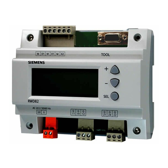
RWD82
RWD32
Siemens Building Technologies
O3341(RWD32) V14.doc
O3341A031En2
O3341A031En2
8-Jun-01
Version 2
RWD82
RWD32
Page 1
Table of
Contents
Previous
Page
Next
Page
1
2
3
4
5
Advertisement
Table of Contents
Need help?
Do you have a question about the RWD32 and is the answer not in the manual?
Ask a question
Questions and answers
Related Manuals for Siemens RWD32
Controller Siemens RWD68 Installation Instructions Manual
(9 pages)
Controller Siemens RWD68 Quick Start Manual
(3 pages)
Controller Siemens RWD82 Installation And Commissioning Manual
(13 pages)
Controller Siemens RWD68U Technical Instructions
Universal controller (12 pages)
Controller Siemens RWD Series Application Manual
(8 pages)
Controller Siemens RWD62U Technical Instructions
Universal controller (12 pages)
Controller Siemens RWD62U Installation And Commissioning Manual
(10 pages)
Controller Siemens RWD44U Installation And Commissioning Manual
(10 pages)
Controller Siemens RWD45U Installation And Commissioning Manual
(13 pages)
Controller Siemens RWD62 Manual
Universal controller (10 pages)
Controller Siemens RWD32S Installation Instructions Manual
(17 pages)
Controller Siemens G3344 Series Installation Instructions Manual
(16 pages)
Controller Siemens RWB27 Timeswitch Installation And Operating Instructions Manual
Timeswitch (8 pages)
Controller Siemens RWF40 Series User Manual
Compact universal controller (56 pages)
Controller Siemens RWI65.02 Manual
Aerogyr (21 pages)
Controller Siemens RWF55.5 User Manual
Compact universal controllers (93 pages)
This manual is also suitable for:
Rwd82
Table of Contents
Print
Rename the bookmark
Delete bookmark?
Delete from my manuals?
Login
Sign In
OR
Sign in with Facebook
Sign in with Google
Upload manual
Upload from disk
Upload from URL


Need help?
Do you have a question about the RWD32 and is the answer not in the manual?
Questions and answers