Siemens RWF40 Series User Manual
Compact universal controller
Hide thumbs
Also See for RWF40 Series:
- User manual (15 pages) ,
- Installation, use and maintenance instructions (52 pages) ,
- Quick start manual (8 pages)
Table of Contents
Advertisement
Quick Links
RWF40...
Compact Universal Controller
optimized for temperature and pressure control through the control of modulating or multi-stage burners
User Manual
The RWF40... controller and this User Manual are intended for use by OEMs which integrate the controller into
their products!
Siemens Building Technologies
Landis & Staefa Division
CC1B7865E
February 10, 2000
Advertisement
Table of Contents

Subscribe to Our Youtube Channel
Related Manuals for Siemens RWF40 Series


Summary of Contents for Siemens RWF40 Series
- Page 1 User Manual The RWF40... controller and this User Manual are intended for use by OEMs which integrate the controller into their products! Siemens Building Technologies Landis & Staefa Division CC1B7865E February 10, 2000...
- Page 2 2/56 CC1B7865E February 10, 2000 Landis & Staefa Division...
-
Page 3: Table Of Contents
Contents Introduction ..................6 General notes .........................6 Description ........................6 Typographical conventions...................7 1.3.1 Warning symbols ......................7 1.3.2 Notification symbols ......................7 1.3.3 Presentation ........................7 Type of unit ...................8 Type field ........................8 Installation ....................9 Installation site and climatic conditions ..............9 Dimensions........................9 Side-by-side mounting....................10 Mounting in a panel cutout..................10 Cleaning the front panel ....................11 Removing the controller module ................11 Electrical connections ............... - Page 4 Operation ....................29 Basic display........................ 30 6.1.1 Meaning of the display and buttons................30 User level........................31 6.2.1 Changing the setpoints....................31 6.2.2 Manual operation of a modulating burner..............33 6.2.3 Manual operation of a two-stage burner................ 33 6.2.4 Start self-setting ......................34 6.2.5 Display of the software version and unit of actual value ..........
- Page 5 Technical data ..................51 11.1 Inputs ..........................51 11.1.1 Analog input 1 (actual value) ..................51 11.1.2 Analog input 2 (external setpoint, setpoint shift) ............51 11.1.3 Analog input 3 (outside temperature)................52 11.1.4 Binary input «D1»......................52 11.1.5 Binary input «D2»......................52 11.2 Outputs .........................52 11.2.1 Output 1 (release of burner)...................52 11.2.2...
-
Page 6: Introduction
1. Introduction 1.1 General notes Please read this User Manual before starting up the controller. Keep the Manual in a place that is accessible to all users at all times. Please help us improve the Manual. Your suggestions will be welcome. All necessary settings and, where required, settings inside the unit are described in this User Manual, for controller software version 126.01.01. -
Page 7: Typographical Conventions
1. Introduction 1.3 Typographical conventions 1.3.1 Warning symbols The signs for Danger and Caution are used in this Manual under the following conditions: Danger This symbol is used where there may be a danger to personnel if the instructions are disregarded or not strictly followed! Caution This symbol is used where there may be damage to equipment or data if the... -
Page 8: Type Of Unit
2. Type of unit 2.1 Type field Location The type field is glued onto the housing. The type designation consists of operating voltage and type reference of the unit. Types Type of unit Description RWF40.000A97 Basic version with 3-position output RWF40.010A97 ¹·... -
Page 9: Installation
3. Installation 3.1 Installation site and climatic conditions − The installation site should be as free as possible from vibrations, dust and corrosive media − The controller should be installed as far away as possible from sources of electromagnetic fields, such as frequency converters or high-voltage ignition transformers Relative humidity: <... -
Page 10: Side-By-Side Mounting
3. Installation 3.3 Side-by-side If several controllers are mounted side-by-side or above one another in a control panel, the minimum spacing must be observed, namely 30.5 mm vertically and 10.5 mm horizontally. 3.4 Mounting in a panel cutout ✱ ✱ ✱ ✱ Place the seal provided onto the controller housing. -
Page 11: Cleaning The Front Panel
3. Installation 3.5. Cleaning the front panel The front panel can be cleaned with normal washing and rinsing agents or detergents. It is not resistant to corrosive acids, caustic solutions and abrasive cleaners, or cleaning with high-pressure cleaners! 3.6 Removing the controller module The controller module can be removed from the housing for servicing. -
Page 12: Electrical Connections
4. Electrical connections 4.1 Installation notes − The choice of cable, the installation and the electrical connections of the controller Safety regulations must conform to the regulations of VDE 0100 «Regulations for the installation of power circuits with nominal voltages below AC 1000 V», or appropriate local regulations −... -
Page 13: Block Diagram
4. Electrical connections 4.2 Block diagram 3 analog inputs Release of burner Input 1: Output 1: Actual value - Relay (N.O. contact) for Pt100, Ni100, Pt1000, Ni1000 thermocouples or standard signals 3-position output Input 2: Output 2: External setpoint, -Relay (reg. unit opens) setpoint shift Ω... -
Page 14: Assignment Of Terminals
4. Electrical connections 4.3 Assignment of terminals Electrical connections may only be made by qualified personnel! 7865z07/1199 Outputs Display LED Terminal no. Connection diagram Relay 1: release of burner Q14 pole Contact protection: Varistor S07K275 Q13 N.O. contact 7865a11/1199 ▲ Relay 2: regulating unit opens Y1 N.O. - Page 15 4. Electrical connections Analog input 1 (actual value) Terminals Connection diagram Thermocouple 7865a03/1099 Resistance thermometer in 3-wire circuit ϑ 7865a04/1099 Resistance thermometer in 2-wire circuit, line compensation through offset correction (OFF1) ϑ 7865a05/1099 Current input DC 0...20 mA, 4...20 mA 7865a06/1099 Voltage input DC 0...1 V, 0...10 V...
- Page 16 4. Electrical connections Binary inputs Terminals Connection diagram Operating mode selector Section 5.2 «High-fire operation» Setpoint shift / changeover Sections 5.4.1...5.4.4 7865a12/1099 Common ground Operating voltage, interface Terminals Connection diagram Operating voltage L1 line AC 100...240 V ±10 %, 48...63 Hz N neutral Technical earth 7865a18/1099...
-
Page 17: Galvanic Separation
4. Electrical connections 4.4 Galvanic separation The diagram shows the maximum potential differences that may exist between the function modules in the controller. 3 analog inputs Limit comparator Input 1: Output 4: Actual value for Pt100, Ni100, - Relay (N.O. contact) Pt1000, Ni1000 thermocouples or standard signals... -
Page 18: Operating Modes
5. Operating modes 5.1 Low-fire operation Low-fire operation means that only small amounts of heat are drawn from the boiler. A two- position controller maintains the setpoint, switching the burner on and off like a thermostat. This control mode is therefore also known as thermostat function. An adjustable Thermostat function switching differential ensures that the switching frequency of the burner can be selected to reduce wear. -
Page 19: Modulating Burner, Modulating Output
5. Operating modes 5.2.2 Modulating burner, modulating output In diagram area (1), the thermostat function is active. In area (2), the controller is controlling to the adjusted setpoint. 7865w05/1099 HYS3 HYS1 100% The positioning signal is delivered as a standard signal via the modulating output. The modulating controller must be available and configured in the unit (optional). -
Page 20: Two-Stage Burner, Modulating Output
5. Operating modes 5.2.4 Two-stage burner, modulating output In this case, a standard binary signal switches the second stage into circuit with analog output «X1» on reaching the switch-on threshold «HYS1» and switches it out of circuit at the lower switch-off threshold «HYS2». 7865w04/1099 HYS3 HYS2... -
Page 21: Setpoint Changeover "Sp1 / Sp2", Analog Setpoint Shift
5. Operating modes 5.4.1 Setpoint changeover «SP1 / SP2», analog setpoint shift C111: XX1X ... XX3X Outside sensor C111 and C112 are described in chapter 8 Heating curve slope H Setting: 0.0 ... 4.0 Weather-dependent setpoint shift: C112: XX0X C112: XX1X SP1 via buttons SP1 via outside sensor C111: XXX2... -
Page 22: Setpoint Changeover "Sp1" / External Setpoint
5. Operating modes 5.4.2 Setpoint changeover «SP1» / external setpoint C111: XX1X ... XX3X Outside sensor C111 and C112 are described in chapter 8 Heating curve slope H Setting: 0.0 ... 4.0 Weather-dependent setpoint shift: C112: XX0X C112: XX1X SP1 via buttons SP1 from outside sensor C111: X1XX ... -
Page 23: Setpoint "Sp1", Analog / Binary Setpoint Shift
5. Operating modes 5.4.3 Setpoint «SP1», analog / binary setpoint shift C111: XX1X ... XX3X Outside sensor C111 and C112 are described in chapter 8 Heating curve slope H Setting: 0.0 ... 4.0 Weather-dependent setpoint shift: C112: XX0X C112: XX1X SP1 via buttons SP1 via outside sensor C111: X6XX ... -
Page 24: External Setpoint, Binary Setpoint Shift
5. Operating modes 5.4.4 External setpoint, binary setpoint shift C111: X1XX ... X5XX C111 and C112 are described in chapter 8 External setpoint C111: XXX1 C111: XXX2 C111: XXX0 Sections 5.4.1 and 5.4.2 Binary setpoint shift No function "Setpoint changeover ..." D2 closed D2 open The values dSP and SP1 are entered at... -
Page 25: Weather-Dependent Setpoint Shift
5. Operating modes 5.5 Weather-dependent setpoint shift The RWF40... can be configured in such a way that if a Landis & Staefa Ni1000 outside sensor (e.g. QAC22) is connected, a weather-dependent setpoint shift is implemented. The minimum and maximum setpoint values can be set by the lower setpoint limit «SPL»... -
Page 26: Heating Curve Slope
5. Operating modes 5.5.1 Heating curve slope Slope «H» of the heating curve can be used to adjust the setpoint in response to the outside temperature, as shown in the diagram. The common origin of the heating curves is set at (20 °C / 20 °C). The effective range of the weather-adjusted setpoint is restricted by the setpoint limits «SPH»... -
Page 27: Response Threshold "Q
5. Operating modes 5.6 Response threshold «Q» The response threshold «Q» defines how long and how low the actual value can drop before the system switches over to high-fire operation. An internal mathematical calculation using an integration function determines the sum of all the areas Q = Q1 + Q2 + Q3 , as shown in the diagram. -
Page 28: Cold Start Of The Plant
5. Operating modes 5.7 Cold start of the plant When a heating system is switched off for a longer period of time, the actual value will fall. To achieve a faster control response, the controller starts immediately in high-fire operation as soon as the control deviation (x-w) has dropped below a certain limit value. This limit is calculated as follows: Limit value = 2 * (HYS1-HYS3) Example... -
Page 29: Operation
6. Operation Assignment of levels All levels can be accessed from the basic display via the button, as shown in the diagram. The upper actual value display (red) indicates the actual value and the parameter values for the various levels. The setpoint and the parameters are indicated in the lower setpoint display (green). -
Page 30: Basic Display
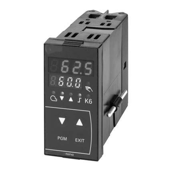
6. Operation 6.1 Basic display The diagram shows the RWF40... after switching on power. This condition is called the basic display. The actual value and the currently active setpoint are shown here. Manual operation, self-setting, the user, parameter and configuration levels can be activated from here. -
Page 31: User Level
6. Operation Initialization All displays are lit up; the setpoint display flashes for about 10 seconds after switching on power. Manual operation The actual value is indicated on the upper display. The LED for manual operation is on. Depending on the operating mode and the type of controller, the setpoint or the level of the manual actuator position is shown on the setpoint display (green). - Page 32 6. Operation Basic display 60.3 65.0 User level 65.0 (Display depends on code 111) EXIT SP 1 10.0 70.0 Depending on the EXIT configuration of binary input 2: - dSP SP 2 -Sp2 Measurement of the 10.0 outside temperature EXIT via analog input 3 50.0 Measurement of the...
-
Page 33: Manual Operation Of A Modulating Burner
6. Operation 6.2.2 Manual operation, modulating burner ✱ ✱ ✱ ✱ EXIT Press for 5 s The LED above the hand symbol lights up. ✱ ✱ ✱ ✱ Change the regulating unit’s position with ▲ and ▼ 3-position controller Relay 2 opens the regulating unit as long as ▲ is pressed. Relay 3 closes the regulating unit as long as ▼... -
Page 34: Start Self-Setting
6. Operation 6.2.4 Start self-setting ✱ ✱ ✱ ✱ + ▼ Start self-setting with ✱ ✱ ✱ ✱ Cancel with ▲ 7865z10/1199 When «tunE» stops flashing, self-setting has stopped. ✱ ✱ ✱ ✱ Accept the parameters that have been determined by pressing ▲ (press the button for at least 2 s!) It is not possible to start «tunE»... -
Page 35: Parameter Level
6. Operation 6.3 Parameter level The parameters involved in the adaptation of the controller to the controlled system are set here after the system has been started up. Within the level, you can proceed to the next parameter by pressing The display of the individual parameters depends on the type of controller. -
Page 36: Parameter Settings
7. Parameter settings The parameter is shown on the lower setpoint display (green) and the value on the upper / actual value display (red). 7865p06/0200 Parameter Display Value range Factory Remarks setting Output 4 Limit value for limit -1999...+9999 digit comparator HYSt Measured value... - Page 37 7. Parameter settings The parameter is shown on the lower / setpoint display (green) and the value on the upper / actual value display (red). 7865p06/0200 Display Parameter Value range Factory Remarks setting Actuator running 10...3000 s 15 s Utilized running time of the valve for time 3-position controllers Switch-on threshold...
-
Page 38: Configuration
8. Configuration 8.1 C111 inputs 0000 C111 7865p03/0200 Analog input 1 Pt100, 3-wire Pt100, 2-wire Ni100, 3-wire Ni100, 2-wire Pt1000, 3-wire, Landis & Staefa IEC 751 Pt1000, 2-wire, Landis & Staefa IEC 751 Ni1000, 3-wire, DIN 43760 Ni1000, 2-wire, DIN 43760 Ni1000, 3-wire, Landis &... - Page 39 8. Configuration 0000 C111 7865p03/0200 Analog input 3 No function Outside sensor Pt1000, 2-wire, Landis & Staefa IEC 751 Outside sensor Ni1000, 2-wire, DIN 43760 Outside sensor Ni1000, 2-wire, Landis & Staefa Function of binary input «D2» No function Setpoint changeover Setpoint shift (binary) Factory setting Landis &...
-
Page 40: C112 Limit Comparator, Controller Type, Setpoint "Sp1", Locking
8. Configuration 8.2 C112 limit comparator, controller type, setpoint «SP1», locking 0000 C112 7865p04/0200 Limit comparator No function (lk off) lk1, input 1 lk2, input 1 lk3, input 1 lk4, input 1 lk5, input 1 lk6, input 1 lk7, input 1 lk8, input 1 lk7, input 2 lk8, input 2... - Page 41 8. Configuration Function Ik1 Window function: relay «K6» is active when the measured value lies within a window around the setpoint (w). Example: w = 80 °C, AL = 5, HYSt = 2 Measured value rising: relay «K6» switches on at 76 °C and off at 86 °C. Measured value falling: relay «K6»...
- Page 42 8. Configuration Function Ik4 As for lk3, but with inverted switching function. Output 4 HYSt Measured value 7865d03e/0300 HYSt = switching differential AL = interval from setpoint Chapter 7 «Parameter settings» Function Ik5 Upper limit signaling Function: relay inactive when measured value > (setpoint + limit value). Example: w = 80 °C, AL = 10, HYSt = 2 Measured value rising: relay «K6»...
- Page 43 8. Configuration Function Ik7 The switching point is independent of the controller setpoint; only the limit value «AL» determines the switching point. Function: relay is active when measured value > limit value. Example: AL = 50, HYSt = 2 Measured value rising: relay «K6» switches on at 51 °C. Measured value falling: relay «K6»...
-
Page 44: C113 Unit Address, Dimensional Unit, Out-Of-Range
8. Configuration 8.3 C113 instrument address, dimensional unit, out-of-range The setting for the decimal place affects actual value-dependent parameters! 0000 C113 7865p05/0200 Unit address Address 0 Address 1 Address 99 Decimal places, dimensional unit No decimal place, °C One decimal place, °C No decimal place, °F One decimal place, °F Signal for out-of-range... -
Page 45: Scl Scaling Of Standard Signal Range Start, Analog Input 1
8. Configuration 8.3.1 «SCL» scaling of standard signal range start, analog input 1 Example SCL = 20; SCH = 100 °C 0 mA (start) corresponds to a measured value of 20 °C 0 mA 20 mA 0 °C 20 °C 100 °C Value range: -1999...+9999 digit Factory setting: 0 digit... -
Page 46: Sch2 Scaling Of Standard Signal Range End, Analog Input 2
8. Configuration 8.3.4 «SCH2» scaling of standard signal range end, analog input 2 Example SCH2 = 80: 20 mA corresponds to a measured value of 80 °C, as already described Value range: -1999...+9999 digit Factory setting: 100 digit 8.3.5 «SPL» lower setpoint limit The controller restricts the setpoints to the value that is set. -
Page 47: Self-Setting Function
9. Self-setting function 9.1 Self-setting function in high-fire operation «tunE» is only possible in high-fire operation, in the «modulating burner» mode. The self-setting function «tunE» is a pure software function unit that is integrated into the controller. In the «modulating» mode of operation, «tunE» tests the response of the controlled system to steps of the positioning signal according to a special procedure. - Page 48 9. Self-setting function Start 7865d13/1099 The controlled system data which are recorded for the forced oscillations are used to calculate the controller parameters «rt, dt, Pb.1» and a filter time constant for actual value filtering that is optimized for this controlled system. −...
-
Page 49: Checking The Controller Parameters
9. Self-setting function 9.2 Checking the controller parameters The optimum adjustment of the controller to the controlled system can be checked by recording a startup sequence with the control loop closed. The following diagrams indicate possible incorrect adjustments, and their correction. Example The response to a setpoint change is shown here for a 3 order controlled system for a... -
Page 50: What To Do If
10. What to do, if ... 10.1 ...numbers are flashing on the display This is an indication that a measured value is not being acquired correctly. The detection of measured value range crossings depends on the type of sensor used. Section 11.3.2 «Measured value circuit monitoring»... -
Page 51: Technical Data
11. Technical data 11.1 Inputs 11.1.1 Analog input 1 (actual value) For resistance thermometers, thermocouples or standard signals with 2 order digital filter (configurable). Resistance thermometers In 2-wire or 3-wire circuit: Type Measured value range Pt100, Pt1000 -200...+850 °C Ni100, Ni1000 DIN 43760 -60...+250 °C Ni1000 from Landis &... -
Page 52: Analog Input 3 (Outside Temperature)
11. Technical data 11.1.3 Analog input 3 (outside temperature) For resistance thermometers in a 2-wire circuit, with fixed filter time constants (21 h 18 min for the weather-dependent setpoint enable) Resistance thermometer Type Measured value range Pt1000 -200...+850 °C Ni1000 DIN 43760 -60...+250 °C Ni1000 from Landis &... -
Page 53: Output 5, Modulating Output (Option)
11. Technical data 11.2.4 Output 5, modulating output (option) Continuous output, electrically isolated from the analog inputs: ∆U < AC 30 V , ∆U < DC 50 V Standard signals Load, burden Load = > 500 Ω DC 0…10 V (short-circuit-proof) Burden = <... -
Page 54: Measured Value Accuracy
11. Technical data 11.3.1 Measured value accuracy Resolution: > 15 bit Measured value accuracy Ambient temperature error Resistance thermometer: ≤ 0.05 % ≤ 50 ppm / K Thermocouples: ≤ 0.25 % ≤ 100 ppm / K Standard signals: ≤ 0.1 % ≤... -
Page 55: Current Settings
12. Actual settings 12.1 Process data Parameter Display Value range Factory Setting setting Setpoint 1 SPL-SPH Setpoint 2 (option) SPL-SPH Digital setpoint shift (optional) SPL-SPH Outside temperature (optional) Section 8.1 «C111 Inputs» Pre-definition of external setpoint SPL-SPH SP.E These parameters are affected by the setting for the decimal place. 12.2 Parameter level Parameter Display... -
Page 56: Configuration Level
Landis & Staefa Division Berliner Ring 23 D - 76347 Rastatt Tel. 0049 - 7222 - 598 - 0 Fax. 0049 - 7222 - 53182 2000 Siemens Building Technologies AG http://www.landisstaefa.com 56/56 CC1B7865E February 10, 2000 Landis & Staefa Division...
Need help?
Do you have a question about the RWF40 Series and is the answer not in the manual?
Questions and answers