Advertisement
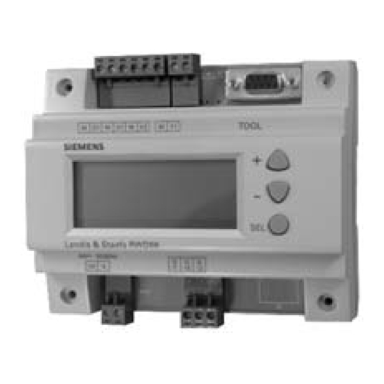
RWD68U
Universal Controller
Description
Features
Product Number
The Universal Controller is intended for heating, air conditioning, ventilation and
refrigeration in comfort control applications. RWD68U main loop control applications
are designed for temperature, static pressure, humidity, air pressure, fluid pressure,
refrigeration, air quality and air fluid velocity control. The controller contains pre-
programmed applications.
Auxiliary control functions include:
• Day/night setpoints
• Remote setpoint control
• Limiter control
• Cascade control
• Maximum priority
• Setpoint compensation
• Summer/winter operation
Control parameters are adjusted for maximum comfort control via three buttons on the
face of the device, or with a laptop computer and Siemens Building Technologies
program software.
NOTE:
For complete supporting technical documentation, including training
presentations, see www.us.sbt.siemens.com/hvp/components.
• Stand-alone electronic temperature controller with P or P+I response
• 24 Vac operating voltage
• Control application selectable via Application Number
• Active input scale can be selectable
• Limit and direction of the output scale can be freely assigned
• Two universal inputs for Siemens 1000 ohm nickel (Ni 1000), 1000 ohm platinum
(Pt 1000) temperature sensors and 0 Vdc to 10 Vdc signals
• Unit can be set as °F, °C, % or no specified unit
• One modulating 0 to 10 Vdc signal output, direct or reverse action
• One two-position output, direct or reverse action
• One digital input for day/night changeover
• Entering or changing of all data via operating buttons on the controller, is possible
without additional tools
• Computer connection for downloading pre-programmed applications via the
software tool
RWD68U
Technical Instructions
Document No. 155-738
January 14, 2005
Siemens Building Technologies, Inc.
Advertisement
Table of Contents

Related Manuals for Siemens RWD68U


Summary of Contents for Siemens RWD68U
- Page 1 • Active input scale can be selectable • Limit and direction of the output scale can be freely assigned • Two universal inputs for Siemens 1000 ohm nickel (Ni 1000), 1000 ohm platinum (Pt 1000) temperature sensors and 0 Vdc to 10 Vdc signals •...
-
Page 2: Specifications
12.64 oz (358 grams) Analog Inputs X1, X2 Controller measuring range -58°F to 302°F (50°C to 150°C) Siemens Ni 1000 ohm @ 32°F Maximum cable length for 14 AWG 984 ft (300 m) (0°C) Pt 1000 ohm at 32°F (0°C) Controller measuring range -4°F to 356°F (-20°C to 180°C) -
Page 3: Function Summary
Maximum priority • Digital input D1 for setpoint changeover day/night Equipment The following Siemens devices can be connected to RWD68U Universal Controllers. Other combinations with units from third-party manufacturers are possible, if the Combinations input and output specifications match the RWD68U. -
Page 4: Software Tool
This tool allows controller programming prior to installation. Functions The RWD68U is a stand-alone universal controller, which performs both primary and auxiliary control functions. The respective mode is defined by entering the Controller Type corresponding configuration and setting parameters via the push buttons on the controller or the software tool. - Page 5 (Application 70 to 79). (Application 30 to 39). Universal Input X1 The primary input for a Siemens Ni 1000 temperature sensor, a Pt 1000 temperature sensor, or a 0 to 10 Vdc active input. Universal Input X2 The secondary input for a Siemens Ni 1000 temperature sensor, a Pt 1000 temperature sensor, an active/passive remote setpoint transmitter, or a 0 to 10 Vdc active input.
-
Page 6: Auxiliary Functions
Technical Instructions RWD68U Universal Controller Document Number 155-738 January 14, 2005 One of the following auxiliary functions can be selected: Auxiliary Functions • P+I limiter (Absolute, #x2 and Relative, #x3) • Remote setpoint, #x1 • Cascade control, #x5 • Setpoint compensation, #x4 •... - Page 7 January 14, 2005 Setpoint Compensation The temperature setpoint X1 is shifted by the temperature as measured at sensor X2. Configuration of the RWD68U defines the influence on setpoint X1. The example shows the room air Temp. temperature setpoint as shifted by the outside temperature.
-
Page 8: Mechanical Design
Terminals Plug-in screw terminals Operating and Display The RWD68U is operated by the buttons on the controller front. Additional tools are Elements not necessary. The controller can also be programmed via the software tool, which plugs into the nine-pin port. -
Page 9: Installation Notes
Electrical Magnetic Interface (EMI), use only shielded cables. • The RWD68U is designed for 24 Vac operating voltage. • Use safety insulating transformers with double insulation; they must be designed for 100% duty. -
Page 10: Wiring Diagrams
NC digital contact NO digital contact Signal input (main input: Siemens Ni 1000, Pt 1000 and Figure 21. RWD68U Wiring Diagram. 0 to10 Vdc) Signal input (aux. Input: Siemens Ni1000, Pt 1000, 0 to10 Vdc and 0 to 1000 Ω or... - Page 11 5.12 (130) In Inches (Millimeters) 4.37 (111) 1.22 (31) Figure 23. RWD68U Controller Dimensions. 5.91 (150) 2.41 (61.2) Figure 24. ARG62.21 Enclosure Dimensions. Information in this publication is based on current specifications. The company reserves the right to make changes in specifications and models as design improvements are introduced.
Need help?
Do you have a question about the RWD68U and is the answer not in the manual?
Questions and answers