Table of Contents
Advertisement
Quick Links
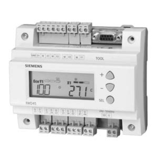
RWD45U Controller
Function
Function Summary
Application
Item Number 129-409, Rev. BA
RWD45U controllers are intended for HVAC and Refrigeration systems including Heat
Pumps. They are suitable for 1-, 2-, and 3-stage compressors.
Input X1 detects the actual room or space temperature and compares it with the
setpoints. Depending on the deviation, the controller acts accordingly with its outputs to
achieve the desired setpoints. The RWD45U controller has a modulating 0 to 10 Vdc
output for economizer control or an additional independent control loop.
•
Controller – Stand-alone controller with four two-position (On/Off) outputs, and one
modulating 0 to 10 Vdc output.
•
Universal input (X1) for the main temperature sensor.
•
Universal input (X2) for the following auxiliary functions:
On/Off (Standby)
Remote setting unit
Alarm
Filter alarm
•
Universal input (X3) for the following functions:
−
Economizer
−
Second independent loop
•
Digital input (D1) for the following digital functions:
−
Day/night changeover setpoint
−
On/Off (Standby)
−
Alarm
−
Filter alarm
•
The RWD45U controller is intended for either DIN rail mounting in a switchboard or
screw mounting with a protective enclosure.
•
Desired output configuration and auxiliary function must be entered for initial set-
up. See Initial Program Settings (New Controller).
The RWD45U has standard pre-configured applications. There are nine main
configuration loops with combinations of ten auxiliary functions. See Table 1.
Installation and
Commissioning Guide
Document No. 129-409
Setpoint reset
Sensor averaging
Winter/Summer setpoint changeover
Sensor select
October 5, 2009
Advertisement
Table of Contents

Subscribe to Our Youtube Channel
Related Manuals for Siemens RWD45U


Summary of Contents for Siemens RWD45U
- Page 1 Input X1 detects the actual room or space temperature and compares it with the setpoints. Depending on the deviation, the controller acts accordingly with its outputs to achieve the desired setpoints. The RWD45U controller has a modulating 0 to 10 Vdc output for economizer control or an additional independent control loop.
- Page 2 Document Number 129-409 RWD45U Controller Installation and Commissioning Guide October 5, 2009 Table 1. Application Numbers. Main Loop H = Heating C = Cooling Cr = Compressor RV = Reversing valve Eco = Economy Auxiliary Loop #1 × (2H2C + Eco Cool) Setpoint reset #3 ×...
- Page 3 RWD45U Controller Installation and Commissioning Guide Document Number 129-409 October 5, 2009 NOTE: Three-stage applications are also used for one- and two-stage applications. Compressor stages are selected during commissioning. Example: Two-stage compressor with reversing valve on heating, economy cooling, and two averaging sensors: #35.
- Page 4 Document Number 129-409 RWD45U Controller Installation and Commissioning Guide October 5, 2009 Table 3. Output Configurations – Q1, Q2, Q3, Q4, and Y1. Application Numbers 10 through 19 Eco Cool 40 through 49 Heating Stage 2 (H2) Heating Stage 1 (H1)
-
Page 5: Display Explanation
RWD45U Controller Installation and Commissioning Guide Document Number 129-409 October 5, 2009 Display Explanation Symbol Description Setting Range Symbol Description Setting Range Main Screen Adjustable setting screen TOOL PC communication port being used Application Numbers 10 through 99 (Not OUT RANGE... -
Page 6: Commissioning Guide
Press the SEL button to save the value (During PS mode, the values are saved only after exiting the PS mode). NOTE: A 9-pin port is provided for optional commissioning via Siemens software tool. See Software Tool (Optional Programming). Page 6 of 13 Siemens Industry, Inc. - Page 7 RWD45U Controller Installation and Commissioning Guide Document Number 129-409 October 5, 2009 Initial Program There are five levels of parameter setting (PS) modes: PS1 through PS4, and a Settings setpoint mode. Each PS has a set of default parameters, which can be changed during commissioning.
- Page 8 Document Number 129-409 RWD45U Controller Installation and Commissioning Guide October 5, 2009 PS 3 – Digital, Auxiliary Function, Eco and Ind. (Y) (Continued) Range/Type Default For Economy mode (Eco) Enter min limit for Eco mode to operate Sensor range 55°F (13°C)
- Page 9 RWD45U Controller Installation and Commissioning Guide Document Number 129-409 October 5, 2009 Main Display The controller is active during main display. (Normal Operation) The main display shows: = Off, ν = On) Whether Q.. is On or Off ( X1 temperature in °F or °C.
-
Page 10: Commissioning Flowchart
Document Number 129-409 RWD45U Controller Installation and Commissioning Guide October 5, 2009 Main Display to PS Mode Press both buttons, and hold for five seconds to enter the PS mode. PS4 will appear first. Press the button to scroll down to the right PS for editing parameters. -
Page 11: Wiring Terminals
RWD45U Controller Installation and Commissioning Guide Document Number 129-409 October 5, 2009 Wiring Terminals G, G0 SELV 24 Vac power supply D1 Digital input M Ground (G0) for signal inputs and universal inputs Q1 to Q4 Relay outputs Max. rating 24... -
Page 12: Installation
Wall-mounted with two screws. (Minimum length of the screws should be 2.75 inches (70 mm) (φ 3.2 mm). Front-mounted using standard elements: • One DIN rail 5.90 inches (150 mm) long for RWD45U • Two hexagonal placeholders 1.96 inches (50 mm) • Washers •... - Page 13 Information in this publication is based on current specifications. The company reserves the right to make changes in specifications and models as design improvements are introduced. . Windows is a registered trademark of Microsoft Corporation. Other product or company names mentioned herein may be the trademarks of their respective owners. © 2009 Siemens Industry, Inc. Siemens Industry, Inc.
Need help?
Do you have a question about the RWD45U and is the answer not in the manual?
Questions and answers