Table of Contents
Advertisement
Advertisement
Table of Contents

Related Manuals for Botex MPX 405


Summary of Contents for Botex MPX 405
- Page 1 MPX 405 dimmer pack...
- Page 2 Musikhaus Thomann Thomann GmbH Hans-Thomann-Straße 1 96138 Burgebrach Germany Telephone: +49 (0) 9546 9223-0 E-mail: info@thomann.de Internet: www.thomann.de 05.12.2017, ID: 152999 (V2)
-
Page 3: Table Of Contents
1.2 Notational conventions........................6 1.3 Symbols and signal words....................... 7 Safety instructions............................. 9 Features............................... 13 Installation and starting up........................ 14 Connections and controls........................16 Operating..............................21 Technical specifications........................24 Plug and connection assignments....................25 Protecting the environment......................26 MPX 405 dimmer pack... -
Page 4: General Notes
If you sell the unit please make sure that the buyer also receives this manual. Our products are subject to a process of continuous development. Thus, they are subject to change. MPX 405 dimmer pack... -
Page 5: Further Information
Our online guides provide detailed information on technical basics Online guides and terms. Personal consultation For personal consultation please contact our technical hotline. If you have any problems with the device the customer service will Service gladly assist you. MPX 405 dimmer pack... -
Page 6: Notational Conventions
The letterings for connectors and controls are marked by square brackets and italics. Examples: [VOLUME] control, [Mono] button. Displays Texts and values displayed on the device are marked by quotation marks and italics. Examples: ‘24ch’ , ‘OFF’ . MPX 405 dimmer pack... -
Page 7: Symbols And Signal Words
ð Automatic operation is started. Switch off the device. 1.3 Symbols and signal words In this section you will find an overview of the meaning of symbols and signal words that are used in this manual. MPX 405 dimmer pack... - Page 8 This combination of symbol and signal word indicates a pos- sible dangerous situation that can result in material and environmental damage if it is not avoided. Warning signs Type of danger Warning – high-voltage. Warning – danger zone. MPX 405 dimmer pack...
-
Page 9: Safety Instructions
Choking hazard! Ensure that children do not detach any small parts (e.g. knobs or the like) from the unit. They could swallow the pieces and choke! Never let children unattended use electrical devices. MPX 405 dimmer pack... - Page 10 DANGER! Electric shock caused by short-circuit Do not modify the mains cable or the plug. Failure to do so could result in electric shock/death or fire. If in doubt, seek advice from a registered electrician. MPX 405 dimmer pack...
- Page 11 Keep the device away from naked flames. NOTICE! Operating conditions This device has been designed for indoor use only. To prevent damage, never expose the device to any liquid or moisture. Avoid direct sunlight, heavy dirt, and strong vibrations. MPX 405 dimmer pack...
- Page 12 Failure to do so could result in damage to the device and possibly injure the user. Unplug the device before electrical storms occur and when it is unused for long periods of time to reduce the risk of electric shock or fire. MPX 405 dimmer pack...
-
Page 13: Features
4 dimmer channels Outputs: 4 protective contact sockets Control via DMX 512 and via buttons and display on the unit Individual DMX addressing per channel Channel function selectable per channel Operating modes: – – Automatic Single channel protection MPX 405 dimmer pack... -
Page 14: Installation And Starting Up
First, connect the loads to the terminals on the sides of the device. If you want to operate the device in ‘DMX’ mode, establish the DMX connection to the controller. Finally, connect the power plug of the device to a mains power socket. MPX 405 dimmer pack... - Page 15 Connect the output of the first DMX device to the input of the second one, and so on to form a daisy chain. Always ensure that the output of the last DMX device in the daisy chain is terminated with a resistor (110 Ω, ¼ W). MPX 405 dimmer pack...
-
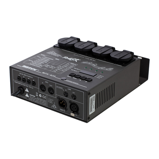
Page 16: Connections And Controls
Connections and controls Connections and controls Front panel MPX 405 dimmer pack... - Page 17 5 Display with additional indicator LEDs [DMX signal]: lights up when the unit is turned on and receives a DMX signal. [MIDI signal]: lights up when the unit is turned on and receives a MIDI signal. MPX 405 dimmer pack...
- Page 18 [Chase]: lights up when the unit is in ‘Chase’ mode. 6 Channel indicators [1]…[4]. In all operating modes, the channel indicators show which channels are currently being used by the running pro- gramme (LEDs light up). MPX 405 dimmer pack...
- Page 19 Connections and controls Bottom MPX 405 dimmer pack...
- Page 20 MIDI signal input socket 9 [MIDI THRU] Output socket for looped-through MIDI signal 10, 11 [LINK IN], [LINK OUT] Connections for master / slave configuration. 12 [DMX OUT] DMX output 13 [DMX IN] DMX input 14 Power cable MPX 405 dimmer pack...
-
Page 21: Operating
Pull the power plug of the unit to turn it completely volt-free. Operating mode selection Switch to normal operation and use [MODE] to select the desired operating mode. Here you have the choice between the modes: Receive (CH:...) Chase (P:...) MPX 405 dimmer pack... - Page 22 ‘P:xx’ . Use [UP] and [DOWN] to select the desired running-light programme ‘P:01’ to ‘P: 16’ . Select running-light speed. Press [MENU] repeatedly until the display shows ‘SP:xx’ . Use [UP] and [DOWN] to adjust the desired running-light speed ‘SP:01’ bis ‘SP:99’ . MPX 405 dimmer pack...
- Page 23 [UP] and [DOWN] to set the desired channel ‘CH:01’ to ‘CH:16’ . Select the MIDI note number. Select ‘MIDI-Note Number’ . Press [MENU] repeatedly until the display shows ‘N:xxx’ . Use [UP] and [DOWN] to set the desired value ‘ N:001’ to ‘N: 128’ . MPX 405 dimmer pack...
-
Page 24: Technical Specifications
Signal input DMX 512 via 3-pin XLR socket Outputs 4 mounting safety socket Temperature range 5 °C … +35 °C Dimensions (W × H × D) 200 mm × 65 mm × 180 mm Weight 2 kg MPX 405 dimmer pack... -
Page 25: Plug And Connection Assignments
The unit offers a 3-pin XLR socket for DMX output and a 3-pin XLR plug for DMX input. Please refer to the drawing and table below for the pin assignment of a suitable XLR plug. Configuration Ground, shielding Signal inverted (DMX–, ‘cold signal’) Signal (DMX+, ‘hot signal’) MPX 405 dimmer pack... -
Page 26: Protecting The Environment
Dispose of this device through an approved waste disposal firm or through your local waste facility. When discarding the device, comply with the rules and regulations that apply in your country. If in doubt, consult your local waste disposal facility. MPX 405 dimmer pack... - Page 28 Musikhaus Thomann · Hans-Thomann-Straße 1 · 96138 Burgebrach · Germany · www.thomann.de...
Need help?
Do you have a question about the MPX 405 and is the answer not in the manual?
Questions and answers