Table of Contents
Advertisement
Quick Links
Download this manual
See also:
Owner's Manual
Advertisement
Table of Contents

Related Manuals for Dell SCv3000


Summary of Contents for Dell SCv3000
- Page 1 SCv3000 and SCv3020 Storage System Deployment Guide...
- Page 2 A WARNING indicates a potential for property damage, personal injury, or death. Copyright © 2018 Dell Inc. or its subsidiaries. All rights reserved. Dell, EMC, and other trademarks are trademarks of Dell Inc. or its subsidiaries. Other trademarks may be trademarks of their respective owners.
-
Page 3: Table Of Contents
Contents About This Guide.............................. 7 Revision History.................................. 7 Audience....................................7 Contacting Dell................................... 7 Related Publications................................7 1 About the SCv3000 and SCv3020 Storage System..................9 Storage Center Hardware Components..........................9 SCv3000 and SCv3020 Storage System........................9 Expansion Enclosures..............................10 Switches..................................10 Storage Center Communication............................. 10 Front-End Connectivity............................. - Page 4 Expansion Enclosure Cabling Guidelines........................51 Back-End SAS Redundancy............................51 Back-End Connections for an SCv3000 and SCv3020 Storage System With Expansion Enclosures....51 SCv3000 and SCv3020 and One SCv300 and SCv320 Expansion Enclosure..........52 SCv3000 and SCv3020 and Two SCv300 and SCv320 Expansion Enclosures..........53 SCv3000 and SCv3020 Storage System and One SCv360 Expansion Enclosure..........54...
- Page 5 Modify iDRAC Interface Settings for a Storage System..................66 Unconfigure Unused I/O Ports..........................66 6 Perform Post-Setup Tasks........................... 67 Update Storage Center Using Storage Manager......................67 Check the Status of the Update............................ 67 Change the Operation Mode of a Storage Center...................... 68 Verify Connectivity and Failover............................
- Page 6 Fault Domain Information............................. 99 Additional Storage Center Information........................100 Fibre Channel Zoning Information..........................100 D HBA Server Settings..........................102 Settings by HBA Manufacturer.............................102 Dell 12 Gb SAS HBAs............................... 102 Cisco Fibre Channel HBAs............................102 Emulex HBAs................................102 QLogic HBAs................................103 Settings by Server Operating System......................... 104 Citrix XenServer...............................
-
Page 7: About This Guide
The information provided in this guide is intended for storage or network administrators and deployment personnel. Contacting Dell Dell provides several online and telephone-based support and service options. Availability varies by country and product, and some services might not be available in your area. - Page 8 Provides information about Storage Manager releases, including new features and enhancements, open issues, and resolved issues. • Dell TechCenter Provides technical white papers, best practice guides, and frequently asked questions about Dell Storage products. Go to http:// en.community.dell.com/techcenter/storage/. About This Guide...
-
Page 9: About The Scv3000 And Scv3020 Storage System
16 3.5-inch drives and the SCv3020 storage system contains up to 30 2.5-inch drives. The SCv3000 Series Storage Center supports up to 222 drives per Storage Center system. This total includes the drives in the storage system chassis and the drives in the expansion enclosures. The SCv3000 and SCv3020 require a minimum of seven hard disk drives (HDDs) or four solid-state drives (SSDs) installed in the storage system chassis or an expansion enclosure. -
Page 10: Expansion Enclosures
SAS – Hosts or servers access storage by connecting directly to the storage system SAS ports. When replication is licensed, the SCv3000 and SCv3020 can use the front-end Fibre Channel or iSCSI ports to replicate data to another Storage Center. - Page 11 SCv3000 and SCv3020 Storage System With Fibre Channel Front-End Connectivity A storage system with Fibre Channel front-end connectivity can communicate with the following components of a Storage Center system. Figure 1. Storage System With Fibre Channel Front-End Connectivity Item Description...
- Page 12 SCv3000 and SCv3020 Storage System With iSCSI Front-End Connectivity A storage system with iSCSI front-end connectivity can communicate with the following components of a Storage Center system. Figure 2. Storage System With iSCSI Front-End Connectivity Item Description Speed Communication Type...
- Page 13 SCv3000 and SCv3020 Storage System With Front-End SAS Connectivity The SCv3000 and SCv3020 storage system with front-end SAS connectivity can communicate with the following components of a Storage Center system. Figure 3. Storage System With Front-End SAS Connectivity Item Description...
- Page 14 You can connect to the front-end port of a storage controller using a direct-attached SFP+ cable or an SFP+ transceiver module. An SCv3000 and SCv3020 storage system with 16 Gb Fibre Channel or 10 GbE iSCSI storage controllers uses short-range small-form-factor pluggable (SFP+) transceiver modules.
- Page 15 Remove the fiber-optic cable that is inserted into the transceiver. Make sure the fiber-optic cable is labeled before removing it. b Press the release clip on the bottom of the cable connector to remove the fiber-optic cable from the transceiver. About the SCv3000 and SCv3020 Storage System...
-
Page 16: Back-End Connectivity
The SCv3000 and SCv3020 storage system supports replication to the storage systems listed below. However, a Storage Manager Data Collector must be used to replicate data between the storage systems. For more information about installing and managing the Data Collector and setting up replications, see the Storage Manager Installation Guide. -
Page 17: Scv3000 And Scv3020 Storage System Hardware
SC9000 SCv3000 and SCv3020 Storage System Hardware The SCv3000 and SCv3020 storage system ships with Dell Enterprise Plus Value drives, two redundant power supply/cooling fan modules, and two redundant storage controllers. Each storage controller contains the front-end, back-end, and management communication ports of the storage system. - Page 18 The SCv3000 and SCv3020 storage system supports Dell Enterprise Plus Value drives. The drives in an SCv3000 storage system are installed horizontally. The drives in an SCv3020 storage system are installed vertically. The indicators on the drives provide status and activity information.
-
Page 19: Scv3000 And Scv3020 Storage System Back-Panel View
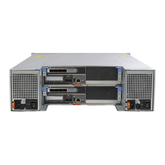
Figure 10. SCv3020 Storage System Drive Numbering SCv3000 and SCv3020 Storage System Back-Panel View The back panel of the storage system contains the storage controller indicators and power supply indicators. Figure 11. SCv3000 and SCv3020 Storage System Back-Panel View Item Name... - Page 20 SCv3000 and SCv3020 Storage Controller Features and Indicators The SCv3000 and SCv3020 storage system includes two storage controllers in two interface slots. SCv3000 and SCv3020 Storage Controller The following figure shows the features and indicators on the storage controller.
- Page 21 – Fast blinking amber (4x per second) – Power good and the pre-operating system is booting • Blinking green – Slow blinking green (2s on, 1s off) – Operating system is booting About the SCv3000 and SCv3020 Storage System...
-
Page 22: Expansion Enclosure Overview
NOTE: The mezzanine card does not support DCB. Expansion Enclosure Overview Expansion enclosures allow the data storage capabilities of the SCv3000 and SCv3020 storage system to be expanded beyond the 30 internal drives in the storage system chassis. • The SCv300 is a 2U expansion enclosure that supports up to 12 3.5‐inch hard drives installed in a four‐column, three-row configuration. - Page 23 Remains solid amber when the expansion enclosure is in the fault state. Hard disk drives • SCv300 – Up to 12 3.5-inch SAS hot-swappable hard disk drives. • SCv320 – Up to 24 2.5-inch SAS hot-swappable hard disk drives. About the SCv3000 and SCv3020 Storage System...
- Page 24 SCv300 and SCv320 Expansion Enclosure Drives Dell Enterprise Plus Value drives are the only drives that can be installed in SCv300 and SCv320 expansion enclosures. If a non-Dell Enterprise Plus Valuedrive is installed, the Storage Center prevents the drive from being managed.
- Page 25 A slide-out label panel that records system information such as the Service Tag Power switches (2) Controls power for the expansion enclosure. There is one switch for each power supply. Power supply unit and cooling fan 600 W power supply module (PS2) About the SCv3000 and SCv3020 Storage System...
- Page 26 Provides SAS connections for cabling the storage controller to the next expansion (Input or Output) enclosure in the chain. (single port, redundant, and multichain configuration). USB Mini-B (serial Not for customer use debug port) Unit ID display Displays the expansion enclosure ID About the SCv3000 and SCv3020 Storage System...
- Page 27 Remains solid blue when the expansion enclosure is in the fault state. SCv360 Expansion Enclosure Drives Dell Enterprise Plus drives are the only drives that can be installed in SCv360 expansion enclosures. If a non-Dell Enterprise Plus drive is installed, the Storage Center prevents the drive from being managed.
- Page 28 The Storage Center identifies drives as XX-YY, where XX is the unit ID of the expansion enclosure that contains the drive, and YY is the drive position inside the expansion enclosure. An SCv360 holds up to 60 drives, which are numbered from left to right in rows starting from 0. Figure 23. SCv360 Drive Numbering About the SCv3000 and SCv3020 Storage System...
- Page 29 Enclosure management EMMs provide the data path and management functions for the expansion enclosure. module 1 Enclosure management EMMs provide the data path and management functions for the expansion enclosure. module 2 About the SCv3000 and SCv3020 Storage System...
- Page 30 Off – Power is not connected SAS ports 1–4 (Input or Provides SAS connections for cabling the storage controller to the next expansion enclosure in Output) the chain (single port, redundant, and multichain configuration). About the SCv3000 and SCv3020 Storage System...
-
Page 31: Install The Storage Center Hardware
Always follow these safety precautions to avoid injury and damage to Storage Center equipment. If equipment described in this section is used in a manner not specified by Dell, the protection provided by the equipment could be impaired. For your safety and protection, observe the rules described in the following sections. -
Page 32: Electrical Safety Precautions
Follow these guidelines to protect your equipment from ESD: • Dell recommends that you always use a static mat and static strap while working on components in the interior of the chassis. • Observe all conventional ESD precautions when handling plug-in modules and components. -
Page 33: General Safety Precautions
The SCv3000 and SCv3020 storage system ships with a ReadyRails II kit. The rails come in two different styles: tool-less and tooled. Follow the detailed installation instructions located in the rail kit box for your particular style of rails. - Page 34 Figure 27. Attach the Rails to the Rack Engage the back end of the rail until it fully seats and the latch locks into place. Engage the front end of the rail until it fully seats and the latch locks into place. Align the system with the rails and slide the storage system into the rack.
- Page 35 Figure 29. Tighten the Screws If the Storage Center system includes expansion enclosures, mount the expansion enclosures in the rack. See the instructions included with the expansion enclosure for detailed steps. Install the Storage Center Hardware...
-
Page 36: Connect The Front-End Cabling
Front-end cabling refers to the connections between the storage system and external devices such as host servers or another Storage Center. Dell recommends connecting the storage system to host servers using the most redundant option available. In addition, make sure that the speed of the HBAs in the storage controller match the speed of the host server. -
Page 37: Connecting To Host Servers With Fibre Channel Hbas
When using Fibre Channel for front-end connectivity, zones must be established to ensure that storage is visible to the servers. Use the zoning concepts discussed in this section to plan the front-end connectivity before starting to cable the storage system. Dell recommends creating zones using a single initiator host port and multiple Storage Center ports. WWN Zoning Guidelines When WWN zoning is configured, a device may reside on any port, or change physical ports and still be visible, because the switch is seeking a WWN. -
Page 38: Cable The Storage System With 2-Port Fibre Channel Io Cards
Host server Fibre Channel switch 1 (member of fault domain 1) Fibre Channel switch 2 (member of fault domain 2) SCv3000 and SCv3020 storage system Steps Connect each host server to both Fibre Channel fabrics. Connect Storage Center fault domain 1 (shown in orange) to fabric 1. -
Page 39: Cable The Storage System With 4-Port Fibre Channel Io Cards
Host server Fibre Channel switch 1 (member of fault domain 1) Fibre Channel switch 2 (member of fault domain 2) SCv3000 and SCv3020 storage system Steps Connect each host server to both Fibre Channel fabrics. Connect fault domain 1 (shown in orange) to fabric 1. -
Page 40: Labeling The Front-End Cables
Labeling the Front-End Cables Label the front-end cables to indicate the storage controller and port to which they are connected. Prerequisite Locate the front-end cable labels that shipped with the storage system. About this task Apply cable labels to both ends of each cable that connects a storage controller to a front-end fabric or network, or directly to host servers. Steps Starting with the top edge of the label, attach the label to the cable near the connector. -
Page 41: Connecting To Host Servers With Iscsi Hbas Or Network Adapters
Host server Host server Ethernet switch 1 (fault domain 1) Ethernet switch 2 (fault domain 2) SCv3000 and SCv3020 storage system Steps Connect each host server to both iSCSI networks. Connect fault domain 1 (shown in orange) to iSCSI network 1. -
Page 42: Cable The Storage System With 4-Port Iscsi Io Cards
Host server Ethernet switch 1 (member of fault domain 1) Ethernet switch 2 (member of fault domain 2) SCv3000 and SCv3020 storage system Steps Connect each host server to both iSCSI networks. Connect fault domain 1 (shown in orange) to iSCSI network 1. -
Page 43: Connect A Storage System To A Host Server Using An Iscsi Mezzanine Card
Host server Ethernet switch 1 (member of fault domain 1) Ethernet switch 2 (member of fault domain 2) SCv3000 and SCv3020 storage system To connect the iSCSI host server to iSCSI networks: Steps Connect each iSCSI host server to both iSCSI networks. -
Page 44: Labeling The Front-End Cables
Labeling the Front-End Cables Label the front-end cables to indicate the storage controller and port to which they are connected. Prerequisite Locate the pre-made front-end cable labels that shipped with the storage system. About this task Apply cable labels to both ends of each cable that connects a storage controller to a front-end fabric or network, or directly to host servers. Steps Starting with the top edge of the label, attach the label to the cable near the connector. -
Page 45: Connecting To Host Servers With Sas Hbas
Connecting to Host Servers with SAS HBAs An SCv3000 and SCv3020 storage system with front-end SAS ports connects directly to host servers with SAS HBAs. Cable the Storage System with 4-Port SAS HBAs to Host Servers with One SAS HBA per Server A storage system with four front-end SAS ports on each storage controller can connect to up to four host servers, if each host server has one SAS HBA with two ports. -
Page 46: Labeling The Front-End Cables
Figure 39. Storage System with Two 4-Port SAS Storage Controllers Connected to Four Host Servers with One SAS HBA per Server Next step Install or enable MPIO on the host servers. NOTE: For the latest best practices, see the Dell Storage Center Best Practices document on the Dell TechCenter site (http:// en.community.dell.com/techcenter/storage/). Labeling the Front-End Cables Label the front-end cables to indicate the storage controller and port to which they are connected. -
Page 47: Attach Host Servers (Fibre Channel)
Contact your solution provider for a list of supported Fibre Channel HBAs. • Refer to the Dell EMC Compatibility Matrix for SC, PS, and FS Series Arrays for a list of supported Fibre Channel HBAs. • Refer to the Appendix A HBA Server Settings for a list of HBA server settings to be used when configuring servers. -
Page 48: Attach The Host Servers (Iscsi)
Contact your solution provider for a list of supported iSCSI HBAs. • Refer to the Dell EMC Compatibility Matrix for SC, PS, and FS Series Arrays for a list of supported HBAs. • If the host server is a Windows or Linux host: Install the iSCSI HBAs or network adapters dedicated for iSCSI traffic in the host servers. -
Page 49: Connect The Management Ports To The Management Network
Label the Ethernet management cables that connect each storage controller to an Ethernet switch. Prerequisite Locate the Ethernet management cable labels that shipped with the SCv3000 and SCv3020 storage system. About this task Apply cable labels to both ends of each Ethernet management cable. - Page 50 Figure 43. Attach Label to Cable Wrap the label around the cable until it fully encircles the cable. The bottom of each label is clear so that it does not obscure the text. Figure 44. Wrap Label Around Cable Apply a matching label to the other end of the cable. Connect the Front-End Cabling...
-
Page 51: Connect The Back-End Cabling
You can connect multiple expansion enclosures to an SCv3000 and SCv3020 by cabling the expansion enclosures in series. However, the SCv3000 and SCv3020 do not support the cabling of SCv300 and SCv320 expansion enclosures on the same SAS chain as SCv360 expansion enclosures. -
Page 52: Scv3000 And Scv3020 And One Scv300 And Scv320 Expansion Enclosure
Storage controller 2 Expansion enclosure The following table describes the back-end SAS connections from an SCv3000 and SCv3020 storage system to one SCv300 and SCv320 expansion enclosure. Table 2. SCv3000 and SCv3020 Connected to One SCv300 and SCv320 Expansion Enclosure... -
Page 53: Scv3000 And Scv3020 And Two Scv300 And Scv320 Expansion Enclosures
Expansion enclosure 1 Expansion enclosure 2 The following table describes the back-end SAS connections from an SCv3000 and SCv3020 storage system to two SCv300 and SCv320 expansion enclosures. Table 3. SCv3000 and SCv3020 Connected to Two SCv300 and SCv320 Expansion Enclosures... -
Page 54: Scv3000 And Scv3020 Storage System And One Scv360 Expansion Enclosure
Storage system Storage controller 1 Storage controller 2 Expansion enclosure The following table describes the back-end SAS connections from an SCv3000 and SCv3020 storage system to one SCv360 expansion enclosure Table 4. SCv3000 and SCv3020 and One SCv360 Expansion Enclosure Path... -
Page 55: Label The Back-End Cables
Storage controller 2 Expansion enclosure 1 Expansion enclosure 2 The following table describes the back-end SAS connections from an SCv3000 and SCv3020 storage system to two SCv360 expansion enclosures. Table 5. SCv3000 and SCv3020 and Two SCv360 Expansion Enclosures Path... - Page 56 Figure 49. Attach Label to Cable Wrap the label around the cable until it fully encircles the cable. The bottom of each label is clear so that it does not obscure the text. Figure 50. Wrap Label Around Cable Apply a matching label to the other end of the cable. Connect the Back-End Cabling...
-
Page 57: Discover And Configure The Storage Center
The Discover and Configure Uninitialized Storage Centers wizard sets up a Storage Center to make it ready for volume creation. Use the Dell Storage Manager to discover and configure the Storage Center. After configuring a Storage Center, you can set up a localhost or VMware vSphere host using the host setup wizards. - Page 58 Steps Make sure that the power switches are in the OFF position before connecting the power cables. Connect the power cables securely to both power supply/cooling fan modules in the storage system chassis. Figure 51. Connect the Power Cables Connect the power cables plugged into the left power supply to one power distribution unit (PDU). Connect the power cables plugged into the right power supply to a second power distribution unit (PDU).
-
Page 59: Locate Your Service Tag
The Service Tag and Express Service Code are found on the front of the system by pulling out the information tag. Alternatively, the information might be on a sticker on the back of the storage system chassis. This information is used by Dell to route support calls to the appropriate personnel.This information is used by the manufacturer to route support calls to the appropriate personnel. -
Page 60: Deploy The Storage Center Using The Direct Connect Method
Use the direct connect method to manually deploy the Storage Center when it is not discoverable. Use an Ethernet cable to connect the computer running the Dell Storage Manager to the management port of the top controller. Cable the bottom controller to the management network switch. -
Page 61: Set System Information
Set System Information Use the Set System Information page to provide Storage Center and storage controller configuration information. This information is needed when connecting to the Storage Center using Storage Manager. Type a descriptive name for the Storage Center in the Storage Center Name field. Type the system management IPv4 address for the Storage Center in the Virtual Management IPv4 Address field. -
Page 62: Configure Key Management Server Settings
• If one or more of the system setup tasks fails, click Troubleshoot Initialization Error to learn how to resolve the issue. • If the Configuring Disks task fails, click View Disks to see the status of the drives detected by the Storage Center. •... -
Page 63: Configure Iscsi Ports
Steps Review the fault domains that have been created. (Optional) Click Copy to clipboard to copy the fault domain information. (Optional) Review the information on the Zoning, Hardware, and Cabling Diagram tabs. NOTE: The ports must already be zoned. Click Next. Configure iSCSI Ports For a Storage Center with iSCSI front-end ports, enter network information for the fault domains and ports. -
Page 64: Configure Time Settings
Using SupportAssist As an integral part of Dell’s ability to provide best-of-class support for your Enterprise-class products, SupportAssist proactively provides the information required to diagnose support issues, enabling the most efficient support possible and reducing the effort required by you. -
Page 65: Update The Storage Center
Next. You will have to use the Storage Center Update Utility to update the Storage Center software before continuing. See the Dell Storage Center Update Utility Administrator’s Guide or contact technical support for detailed instructions about using the Storage Center Update Utility. -
Page 66: Modify Idrac Interface Settings For A Storage System
Unconfigure Unused I/O Ports Unconfigure a port when it is down and will not be used. Prerequisites • The Storage Center must be a SCv3000 and SCv3020 storage system. • The I/O port must be down. Steps Click the Storage view. -
Page 67: Perform Post-Setup Tasks
Perform Post-Setup Tasks Perform connectivity and failover tests to make sure that the Storage Center deployment was successful. NOTE: Before testing failover, use Storage Manager to place the storage system in Maintenance mode. When you are finished, use Storage Manager to place the storage system back into normal operational mode. Topics: •... -
Page 68: Change The Operation Mode Of A Storage Center
In the Storage view, select a Storage Center. b Click the Storage tab, then click Servers > Create Server from Localhost. Connect to the Storage Center using the Dell Storage Manager. Create two small test volumes (TestVol1 and TestVol2) on the server. -
Page 69: Test Storage Controller Failover
Test Storage Controller Failover Test the Storage Center to make sure that a storage controller failover does not interrupt I/O. About this task NOTE: Before restarting a storage controller, use Storage Manager to change the operation mode to Maintenance mode. When you are finished, use Storage Manager to place the storage system back into normal operational mode. -
Page 70: Send Diagnostic Data Using Supportassist
Steps Use Storage Manager to connect to the Storage Center. Click the Storage tab. From the Storage tab navigation pane, select the Volumes node. Create new volumes for the customer in each tier as required by their application. Select the test volumes to delete. Right-click on the selected volumes and select Delete. -
Page 71: Adding Or Removing Expansion Enclosures
Adding or Removing Expansion Enclosures This section describes how to add an expansion enclosure to a storage system and how to remove an expansion enclosure from a storage system. Adding Expansion Enclosures to a Storage System Deployed Without Expansion Enclosures Install the expansion enclosures in a rack, but do not connect the expansion enclosures to the storage system. -
Page 72: Add The Scv300 And Scv320 Expansion Enclosures To The A-Side Of The Chain
Select the Storage tab. b In the Storage tab navigation pane, select the Disks node. On the Disks tab, record the number of drives that are accessible by the Storage Center. Compare this value to the number of drives accessible by the Storage Center after adding expansion enclosures to the storage system. -
Page 73: Add The Scv300 And Scv320 Expansion Enclosures To The B-Side Of The Chain
Figure 54. Connect the A-Side Cables to the Expansion Enclosures Storage system Storage controller 1 Storage controller 2 Expansion enclosure 1 Expansion enclosure 2 Label the back-end cables. Add the SCv300 and SCv320 Expansion Enclosures to the B- Side of the Chain Connect the expansion enclosures to one side of the chain at a time to maintain drive availability. -
Page 74: Install New Scv360 Expansion Enclosures In A Rack
Figure 55. Connect the B-Side Cables to the Expansion Enclosures Storage system Storage controller 1 Storage controller 2 Expansion enclosure 1 Expansion enclosure 2 Label the back-end cables. Install New SCv360 Expansion Enclosures in a Rack Install the expansion enclosures in a rack, but do not connect the expansion enclosures to the storage system. For more information, see the SCv360 Expansion Enclosure Getting Started Guide About this task Steps... - Page 75 Figure 56. Cable the Expansion Enclosures Together Expansion enclosure 1 Expansion enclosure 2 Connect to the Storage Center using the Storage Manager Client. Check the drive count of the Storage Center system before adding the expansion enclosure. Make sure the number of drives installed plus the drives in the new expansion enclosure does not exceed 500 drives.
-
Page 76: Add The Scv360 Expansion Enclosures To The A-Side Of The Chain
Add the SCv360 Expansion Enclosures to the A-Side of the Chain Connect the expansion enclosures to one side of the chain at a time to maintain drive availability. Cable the expansion enclosures to the A-side of the chain. Connect a SAS cable from storage controller 1: port 1 to the first expansion enclosure in the chain, left EMM, port 1. b Connect a SAS cable from storage controller 2: port 2 to the last expansion enclosure in the chain, left EMM, port 3. - Page 77 Figure 58. Disconnect B-Side Cable from the Existing Expansion Enclosure Storage system Storage controller 1 Storage controller 2 Expansion enclosure 1 New expansion enclosure (2) Use a new SAS cable to connect expansion enclosure 1: right EMM, port 3 to the new expansion enclosure (2): right EMM, port 1. Connect the B-side cable that was disconnected in step 1 to the new expansion enclosure (2): right EMM, port 3.
-
Page 78: Adding A Single Expansion Enclosure To A Chain Currently In Service
To add an expansion enclosure to an existing chain, connect the expansion enclosure to the end of the chain. Steps Connect to the Storage Center using the Dell Storage Manager. Check the drive count of the Storage Center system before adding the expansion enclosure. -
Page 79: Check The Drive Count
b In the Storage tab navigation pane, select the Disks node. Click Manage Unassigned Disks. The Manage Unassigned Disks dialog box opens. d From the Disk Folder drop-down menu, select the drive folder for the unassigned drives. Select Perform RAID rebalance immediately. Click OK. -
Page 80: Add An Scv300 And Scv320 Expansion Enclosure To The B-Side Of The Chain
Figure 61. Connect A-Side Cables to the New Expansion Enclosure Storage system Storage controller 1 Storage controller 2 Expansion enclosure 1 New expansion enclosure (2) Label the back-end cables. Add an SCv300 and SCv320 Expansion Enclosure to the B- Side of the Chain Connect the expansion enclosure to one side of the chain at a time to maintain drive availability. - Page 81 Figure 62. Disconnect B-Side Cable from the Existing Expansion Enclosure Storage system Storage controller 1 Storage controller 2 Expansion enclosure 1 New expansion enclosure (2) Use a new SAS cable to connect expansion enclosure 1: bottom EMM, port 2 to the new expansion enclosure (2): bottom EMM, port Connect the B-side cable that was disconnected in step 1 to the new expansion enclosure (2): bottom EMM, port 2.
-
Page 82: Add An Scv360 Expansion Enclosure To The A-Side Of The Chain
Storage controller 2 Expansion enclosure 1 New expansion enclosure (2) Add an SCv360 Expansion Enclosure to the A-Side of the Chain Connect the expansion enclosure to one side of the chain at a time to maintain drive availability. Turn on the expansion enclosure being added. When the drives spin up, make sure that the front panel and power status LEDs show normal operation. -
Page 83: Add An Scv360 Expansion Enclosure To The B-Side Of The Chain
Figure 65. Connect A-Side Cables to the New Expansion Enclosure Storage system Storage controller 1 Storage controller 2 Expansion enclosure 1 New expansion enclosure (2) Label the back-end cables. Add an SCv360 Expansion Enclosure to the B-Side of the Chain Connect the expansion enclosure to one side of the chain at a time to maintain drive availability. - Page 84 Figure 66. Disconnect B-Side Cable from the Existing Expansion Enclosure Storage system Storage controller 1 Storage controller 2 Expansion enclosure 1 New expansion enclosure (2) Use a new SAS cable to connect expansion enclosure 1: right EMM, port 3 to the new expansion enclosure (2): right EMM, port 1. Connect the B-side cable that was disconnected in step 1 to the new expansion enclosure (2): right EMM, port 3.
-
Page 85: Removing An Expansion Enclosure From A Chain Currently In Service
Figure 67. Connect B-Side Cables to the New Expansion Enclosure Storage system Storage controller 1 Storage controller 2 Expansion enclosure 1 New expansion enclosure (2) Removing an Expansion Enclosure from a Chain Currently in Service To remove an expansion enclosure, you disconnect the expansion enclosure from one side of the chain at a time. About this task During this process, one side of the chain is disconnected. -
Page 86: Release The Drives In The Expansion Enclosure
b Reconnect the B-side cables to exclude the expansion enclosure from the chain. Click Next to validate the cabling. Click Finish. Release the Drives in the Expansion Enclosure Release the drives in an expansion enclosure before removing the expansion enclosure. About this task Because releasing drives causes all of the data to move off the drives, this procedure might take some time. - Page 87 Figure 68. Disconnecting the A-Side Cables from the Expansion Enclosure Storage system Storage controller 1 Storage controller 2 Expansion enclosure 1 Expansion enclosure 2 Connect the A-side cable to expansion enclosure 2: top EMM, port 1. Figure 69. Reconnecting the A-Side Cable to the Remaining Expansion Enclosure Storage system Storage controller 1 Adding or Removing Expansion Enclosures...
-
Page 88: Disconnect The Scv300 And Scv320 Expansion Enclosure From The B-Side Of The Chain
Storage controller 2 Expansion enclosure 1 Expansion enclosure 2 Disconnect the SCv300 and SCv320 Expansion Enclosure from the B-Side of the Chain Disconnect the B-side cables from the expansion enclosure that you want to remove. Disconnect the B-side cable (shown in blue) from expansion enclosure 1: bottom EMM, port 1. The A-side cables continue to carry I/O while the B-side is disconnected. -
Page 89: Disconnect The Scv360 Expansion Enclosure From The A-Side Of The Chain
Figure 71. Reconnecting the B-Side Cable to the Remaining Expansion Enclosure Storage system Storage controller 1 Storage controller 2 Disconnected expansion enclosure Expansion enclosure 1 Disconnect the SCv360 Expansion Enclosure from the A-Side of the Chain Disconnect the A-side cables from the expansion enclosure that you want to remove. Disconnect the A-side cable (shown in orange) from expansion enclosure 1: left EMM, port 1. - Page 90 Figure 72. Disconnecting the A-Side Cables from the Expansion Enclosure Storage system Storage controller 1 Storage controller 2 Expansion enclosure 1 Expansion enclosure 2 Connect the A-side cable to expansion enclosure: left EMM, port 1. Adding or Removing Expansion Enclosures...
-
Page 91: Disconnect The Scv360 Expansion Enclosure From The B-Side Of The Chain
Figure 73. Reconnecting the A-Side Cable to the Remaining Expansion Enclosure Storage system Storage controller 1 Storage controller 2 Expansion enclosure 1 Expansion enclosure 2 Disconnect the SCv360 Expansion Enclosure from the B-Side of the Chain Disconnect the B-side cables from the expansion enclosure that you want to remove. Disconnect the B-side cable (shown in blue) from expansion enclosure 1: right EMM, port 1. - Page 92 Figure 74. Disconnecting the B-Side Cables from the Expansion Enclosure Storage system Storage controller 1 Storage controller 2 Expansion enclosure Connect the B-side cable to expansion enclosure 2: right EMM, port 1. The expansion enclosure is now disconnected and can be removed. Figure 75.
- Page 93 Storage controller 2 Expansion enclosure 1 Expansion enclosure 2 Adding or Removing Expansion Enclosures...
-
Page 94: Troubleshooting Storage Center Deployment
Troubleshooting Storage Center Deployment This section contains troubleshooting steps for common Storage Center deployment issues. Troubleshooting Storage Controllers To troubleshoot storage controllers: Check the status of the storage controller using Storage Manager. Check the position of the storage controllers. Check the pins and reseat the storage controller. Remove the storage controller. -
Page 95: A Set Up A Local Host Or Vmware Host
Set Up a Local Host or VMware Host After configuring a Storage Center, you can run the Storage Manager Client on a Windows or Linux host to set up block level storage. In addition, you can set up block-level storage for a VMware ESXi host, or multiple VMware ESXi hosts in a vSphere cluster. Set Up a Local Host from Initial Setup Configure the local host from Initial Setup to access block-level storage on the Storage Center. -
Page 96: Set Up Multiple Vmware Esxi Hosts In A Vmware Vsphere Cluster
The server definition is created on the Storage Center. The Host Setup Successful page displays the best practices that were set by the wizard and best practices that were not set. Make a note of any best practices that were not set by the wizard. It is recommended that these updates be applied manually before starting I/O to the Storage Center. -
Page 97: B Initialize The Storage Center Using The Usb Serial Port
Install the serial port driver as a standard Windows driver. The serial port for the SCv3000 and SCv3020 storage controller is an FT4232 USB device, which has four console ports. Only two ports are used when working with SCv3000 and SCv3020 storage systems: •... -
Page 98: Discover The Storage Center Using The Setup Utility
• Port 2 is used to communicate with the iDRAC. Steps Make sure the micro-USB serial port cable is connected to the computer and the micro-USB connector on the top storage controller. Open a terminal emulator program on the computer. To facilitate troubleshooting, enable logging in the terminal emulator. -
Page 99: C Worksheet To Record System Information
Worksheet to Record System Information Use the following worksheet to record the information that is needed to install the SCv3000 and SCv3020 storage system. Storage Center Information Gather and record the following information about the Storage Center network and the administrator user. -
Page 100: Additional Storage Center Information
(Four port HBA only) IPv4 address for storage controller module 1: port 3 ___ . ___ . ___ . ___ (Four port HBA only) IPv4 address for storage controller module 2: port 3 ___ . ___ . ___ . ___ Table 10. - Page 101 Table 13. Virtual WWNs in Fault Domain 1 Virtual WWN of storage controller 1: port 1 ________________ Virtual WWN of storage controller 2: port 1 ________________ (4-port HBA only) Virtual WWN of storage controller 1: port 3 ________________ (4-port HBA only) Virtual WWN of storage controller 2: port 3 ________________ Table 14.
-
Page 102: D Hba Server Settings
SC, PS, and FS Series Arrays. Dell 12 Gb SAS HBAs Dell 12 Gb SAS HBAs are fully compatible with Storage Center and do not require further configuration. Cisco Fibre Channel HBAs Cisco manufactures Fibre Channel HBAs that are compatible with Storage Centers. -
Page 103: Qlogic Hbas
QLogic HBAs Qlogic manufactures HBAs that are compatible with Storage Centers. NOTE: For more information regarding the compatibility of an HBAs, see the Dell EMC Compatibility Matrix for SC, PS, and FS Series Arrays. For more information about QLogic, see www.qlogic.com Configure QLogic HBA Settings Configure QLogic HBA settings to enable the HBA to communicate more effectively with the Storage Center. -
Page 104: Settings By Server Operating System
/etc directory. When finished, save the file and reboot the server. The following code provides an example: defaults { user_friendly_names no replace_wwid_whitespace yes dev_loss_tmo 30 NOTE: The default value for the dev_loss_tmo timeout setting is 30. However, Dell recommends that the default is set to 60. HBA Server Settings... -
Page 105: Microsoft Windows Server
Table 20. Citrix XenServer HBA Settings for Version 6.5 and Later Field Setting dev_loss_tmo Microsoft Windows Server Double-check that the timeout value for a Microsoft Windows Server is set to 60 seconds. Make sure that the TimoutValue is set to 60 in the following Registry Editor location. HKEY_LOCAL_MACHINE\SYSTEM\CurrentControlSet\Services\Disk NOTE: It is recommended that the latest service pack be installed prior to installing the clustering service. -
Page 106: Novell Netware
Novell Netware Servers running Novell Netware require that the portdown value be reconfigured to allow enough time for the storage systems to fail over. To the end of the Fibre Channel driver load line of nwserver/startup.ncf add : /LUNS /ALLPATHS /ALLPORTS /PORTDOWN=60 Red Hat Enterprise Linux Timeout values determine the time a server waits before destroying a connection after losing connectivity. - Page 107 Emulex HBA Settings Path Configuration Timeout Setting Single Path options lpfc lpfc_devloss_tmo=60 Multipath options lpfc lpfc_devloss_tmo=5 HBA Server Settings...
-
Page 108: E Iscsi Settings
Switch port settings for server NICs and other switch ports in the switch network should be set to ON. Flow Control Dell recommends the following settings as best practice when enabling flow control: • A minimum of receive (RX) flow control should be enabled for all switch interfaces used by servers or storage systems for iSCSI traffic. -
Page 109: Other Iscsi Settings
In the iSCSI area of the IO Ports tab, the Description column displays the model numbers of the iSCSI I/O cards. Other iSCSI Settings The following tables lists Dell recommended iSCSI settings and best practices. Table 23. Recommended iSCSI HBA Settings...
Need help?
Do you have a question about the SCv3000 and is the answer not in the manual?
Questions and answers