
Related Manuals for Vigilant MX1


Summary of Contents for Vigilant MX1
-
Page 1: Fire Alarm System
Vigilant MX1 Fire Alarm System Operator Manual Vigilant MX1 Sample MX1 Fire Alarm System MX1 V1.60 NZS 4512:2010 05:04:07 Normal 12/02/15 LT0344 Issue 2.4... - Page 2 Vigilant MX1 Operator Manual Document: LT0344 Page ii 8 August 2017 Issue 2.4...
- Page 3 Document: LT0344 Vigilant MX1 Operator Manual Issue 2.4 8 August 2017 Page iii...
- Page 4 Vigilant MX1 Operator Manual Document: LT0344 Welcome The VIGILANT MX1 is an innovative analogue addressable fire indicator panel incorporating the latest technology. It complies with New Zealand Standards including NZS 4512:2010 and incorporates an integral Fire Brigade Panel to the Australian standard AS 4428.3. It also complies with Australian Standard AS 7240-2:2004.
- Page 5 Information document revision date and are subject to change without notice. VIGILANT, MX VIRTUAL, MX DIGITAL, and MX FASTLOGIC are trademarks of Johnson Controls. VESDA is a trademark of Xtralis Pty Ltd. No part of this document may be...
- Page 6 Some of the operation of the MX1 as described in this manual is dependent on the site-specific configuration performed by the installer. If the configuration is non- standard, then operation may differ from this manual and compliance to local Standards may be invalidated.
-
Page 7: Table Of Contents
Document: LT0344 Vigilant MX1 Operator Manual Table of Contents Chapter 1 Introduction ................ 1-1 How to Use this Manual _________________________________ 1-2 System Operation ______________________________________ 1-3 Basic System Function __________________________________ 1-4 Operator Interface ______________________________________ 1-5 Normal Appearance of Operator Interface ___________________ 1-6... - Page 8 Vigilant MX1 Operator Manual Document: LT0344 Chapter 7 Logging On to Access Level 3 .......... 7-1 Logging On to Access Level 3 ____________________________ 7-1 Chapter 8 Other Service Functions ........... 8-1 Front Panel Display Test _________________________________ 8-1 Setting System Time and Date ____________________________ 8-2...
-
Page 9: Chapter 1 Introduction
Vigilant MX1 Operator Manual Chapter 1 Introduction This chapter provides an overview of the VIGILANT MX1 system function Introduction and describes the normal appearance of the operator interface. It also describes the concept of Access Levels for access to commands, and the conventions used in this manual to refer to parts of the display when describing these commands. -
Page 10: How To Use This Manual
more detailed service functions that require access to the inside of the cabinet, or use of more advanced diagnostic functions for fault finding or performance analysis. These and other topics are covered in the “MX1 System Design Manual”, part number LT0361 and the “MX1 Service Manual”, part number LT0366. -
Page 11: System Operation
Physical The MX1 is supplied in a compact metal cabinet with an integrated Fire Brigade Panel and operator keypad and display. Space is provided for Zone Status indicators in rear and front service formats. -
Page 12: Basic System Function
It monitors and controls ancillary building equipment (fan controls, relays, door holders, etc.) It supervises devices, transmission paths (circuits), and internal functions of the MX1 to indicate a fault condition should there be a problem. The MX1 operator interface allows an operator to monitor and control the site-specific components connected to the MX1. -
Page 13: Operator Interface
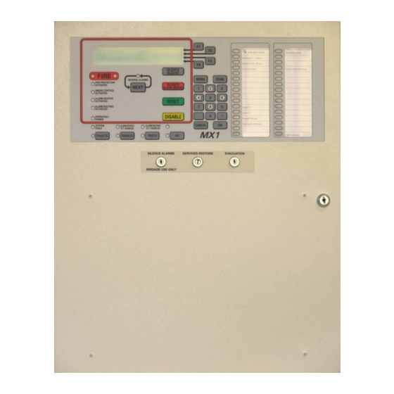
Document: LT0344 Vigilant MX1 Operator Manual Operator Interface Alphanumeric Liquid Crystal Zone LED Soft Keys Display (LCD) Indicators Vigilant MX1 Office Sample MX1 Site Name Factory MX1 V1.60 AS 7240.2 05:40:47 Normal 11/02/15 Shop Garage Shed Fire Brigade Panel Indicators... -
Page 14: Normal Appearance Of Operator Interface
2 lines of the LCD to more alarms. FIRE PROTECTION ACTIVATED This indicator lights red to indicate that fire protection systems associated with this MX1 system have activated. Note that if fire protection systems are not installed, this indicator will not light. SMOKE CONTROL ACTIVATED This indicator lights red to indicate that smoke control systems associated with this MX1 system have activated. - Page 15 Document: LT0344 Vigilant MX1 Operator Manual OPERATING/POWER (GREEN LED) This indicator has three states; On (mains power is on) Flashing (mains power is off or disconnected, panel is running from battery power) Off (panel is not receiving any power and is not operating).
- Page 16 Manual SILENCE BUZZER Controls Pressing the SILENCE BUZZER key will silence the MX1’s internal buzzer. This function can be accessed from Level 1 and higher. If another event that activates the buzzer occurs the buzzer will sound again. The fault buzzer may also be silenced if an optional external Silence Buzzer input is activated.
- Page 17 Document: LT0344 Vigilant MX1 Operator Manual The yellow FAULTS LED will illuminate when one or more faults are present. Refer to “Viewing Faults” (page 3-2) for more information. DISABLES This function can be accessed from Level 2 and higher. It allows the operator to view zones, points or alarm devices that are in the Disabled state, and to enable them.
-
Page 18: Operator Commands
Operator Commands In nearly all cases, the operator commands described in this manual consist of a series of keypresses on the keyboard on the front of the MX1 panel. Some of the keys have fixed labels and meanings, for example, the key labelled “NEXT”... -
Page 19: Operator Access Levels
Level 2 45º anti-clockwise to enable this level, or for 15U cabinets unlock and open the door. The MX1 will automatically return to Access Level 0 or 1 when the door lock is returned to its fully locked position. At Access Level 2, you can: ... -
Page 20: Smoke Control/As 1668 Fan Panel
The operation of this will be site-specific, but in general the Fire Mode Reset button will need to be pressed after the MX1 is reset from alarm to clear the latching fire mode on the fan controls. - Page 21 Point information can be accessed from the MX1 front panel. Used when networking MX1 panels. The SID is a unique number in the range 1-254 (address) allocated to each panel or device on the network.
- Page 22 0, but will not prevent the fault being indicated on the other points. For accessing a point on another MX1 panel in a networked system, the SID of the other panel is multiplied by 1000 and added to the equipment number.
- Page 23 NEXT MENU Fig 1-3 – Example of Point Display A zone is a search area of a building or facility protected by the MX1 fire Zones alarm system. The limits of a zone are defined in NZS 4512. The zone description is used by fire-fighters to quickly locate and respond to alarms.
- Page 24 For accessing a zone on another MX1 panel in a networked system, the SID of the other panel is multiplied by 1000 and added to the zone number. For example, to access zone 37 on an MX1 panel with a SID of 9 you would use the zone number 9037.
- Page 25 CANCEL key has been held or pressed a number of times to get Base Display back to the top display. The MX1 may be showing normal, faults, disables. The Alarm List is a special base display (but is not classified as the Base Display in this manual).
-
Page 26: Nuisance Alarms
Vigilant MX1 Operator Manual Document: LT0344 uisance Alarms Nuisance alarms (also called false alarms or unwanted alarms) are alarm conditions caused by events other than a fire. These can be generally categorised according to two causes: The detector has correctly sensed the phenomena it is designed to detect, but the reason for the phenomena being present is not a fire. - Page 27 Document: LT0344 Vigilant MX1 Operator Manual Detectors should not be located where they can be exposed to dust, heat or other phenomena that can adversely affect them. If they are no longer in a suitable position or are not of a suitable type for the location, contact the service company to discuss relocation or changing the detector type.
-
Page 29: Chapter 2 Managing Alarm Conditions
LCD, and (generally) by activating the building’s alarm devices and alarm routing output to the fire brigade. This chapter describes how MX1 displays alarms and how to use the keypad to investigate and manage alarm conditions. The alarms can be viewed on the LCD at Access Level 1. To reset or disable alarms will require Access Level 2. -
Page 30: Viewing Alarms
Vigilant MX1 Operator Manual Document: LT0344 Viewing Alarms When the first alarm condition is detected by the MX1, it does the following to indicate the presence of the alarm: The red general Fire indicators light red and individual Zone Alarm What the MX1 indicators (if fitted) flash red. - Page 31 Document: LT0344 Vigilant MX1 Operator Manual To silence the internal alarm buzzer in the MX1 cabinet, press the Silencing the SILENCE BUZZER key. This can be done at Access Level 1. Buzzer Acknowledging To acknowledge an alarm press ACKF4. If more than one device is in Alarms alarm, press NEXTF3 or PREVF2, as described above, to step to the...
-
Page 32: Resetting Zones In Alarm
(“Resetting Zones in Alarm”) for instructions for resetting and enabling these zones. On a networked system the MX1 may be configured to allow you to silence alarm devices on remote panels. Refer to Silencing Remote Alarm Devices in Chapter 9. -
Page 33: Disabling Zones In Alarm
Alarms From Other Sources Other alarm types, such as sprinkler systems, pump run status, etc., may be connected to the MX1 and displayed in a number of ways. The sprinkler system will normally activate the alarm routing and alarm devices independently of the MX1, but use the MX1 to simply indicate that the sprinkler system has operated and may also show which flow switches are operating within the building. - Page 34 Vigilant MX1 Operator Manual Document: LT0344 The MX1 may be configured for some smoke detectors to work in Residential residential mode (often used in permanently occupied apartments where Mode the occupant can take action if smoke is indicated). An alarm on such a...
-
Page 35: Chapter 3 Managing Faults And Disables
Conditions may affect its ability to function correctly. The MX1 continually checks the condition of its internal and external components, and will generate indications on the front panel and signals to the fault routing equipment, etc., when it detects a fault. -
Page 36: Viewing Faults
Disable Menu Options Viewing Faults When a fault condition that has not been disabled is detected by the How the MX1 MX1, the operator interface does the following: Indicates the The Common Defect LED will be on. Presence of a ... - Page 37 Document: LT0344 Vigilant MX1 Operator Manual This function requires Access Level 2. Viewing the Fault Details If the Faults indicator is lit, press FAULTS to display the first item in fault. Pressing FAULTS will work from most displays as well as the base display.
-
Page 38: Viewing Disables
Vigilant MX1 Operator Manual Document: LT0344 indicated on the system. However, events for only point 0 will be logged to the event history or to the printer, so as to not unnecessarily fill the event history. Fault indications for points are usually non-latching, i.e., when the point fault is cleared, the fault indication will automatically clear. - Page 39 Document: LT0344 Vigilant MX1 Operator Manual Vigilant MX1 Site Name MX1 V1.34 NZS 4512:2003 09:48:27 System is off-normal 15/01/10 Fig 3-3 – Operator Interface Showing Disables Condition Viewing the To view the list of disabled items, press the DISABLES key.
-
Page 40: Disable Menu Options
Vigilant MX1 Operator Manual Document: LT0344 This function requires Access Level 2. Enabling a Disabled Item To enable a disabled item: Press DISABLES to display the Disables list. Step through the Disables list with NEXTF3 or PREVF2 to the zone or point to be enabled. - Page 41 Ancillary This function requires Access Level 2. Groups Many MX1 installations have functionality for control of lifts, air- conditioning systems and so forth during alarm conditions. When the panel is undergoing tests it may be necessary to disable this functionality in order to avoid disruption to site occupants.
- Page 42 Vigilant MX1 Operator Manual Document: LT0344 The Disable Ancils command provides a convenient means to enable or disable this functionality without having to address each individual function. From the Disable menu press ANCILSF4. This gives a display such as follows.
-
Page 43: Chapter 4 Viewing The Event History
Vigilant MX1 Operator Manual Chapter 4 Viewing the Event History The MX1 maintains a history of the 900 most recent events that have Introduction occurred. These are stored in non-volatile memory, so are not lost on power down. When the history is full, the oldest event is deleted so a new event can be added. -
Page 44: Viewing Event History
This function requires Access Level 2. Displaying Event History If the MX1 display is not showing one of the base displays, i.e., Normal, Off-Normal, Fault or the Alarm list, press and hold CANCEL until the current base display is shown. -
Page 45: Zone Events
Document: LT0344 Vigilant MX1 Operator Manual NEXT or NEXTF3 steps to the next (later) event. History PREVF2 steps to the previous (earlier) event. Navigation OLDESTF1 shows the oldest event in the log. Keys NEWESTF4 shows the newest (most recent) event. - Page 46 Vigilant MX1 Operator Manual Document: LT0344 The <zone text> is the descriptive text for the zone. The <event text> is one of the following: Zone Events Text Event Text Meaning Activate This zone has become Active (distinct from Alarm state). Output points mapped to the zone become operated.
-
Page 47: Point Events
Document: LT0344 Vigilant MX1 Operator Manual Point Events <time> <date> OLDEST Point <n> PREV <event text> NEXT <point text> NEWEST Fig 4-7 – Point Event Message Format The <point text> is the configured descriptive text for this point. The <event text> is one of the following:... -
Page 48: System Events
Bad Event The event code was not recognised by the panel. Cold start The MX1 has been powered up. Command Received A zone or point command has been received on the network from the specified SID. Commission Mode On/Off Commissioning mode has been started/stopped. - Page 49 The printer queue was over filled, so some events to be printed were lost. Reboot xxx yyyyyyyy The MX1 internal checking routines have detected an inconsistency that needs to be addressed. Xxx, yyyyyyyy show the details of the fault. If this occurs repeatedly contact your service company.
-
Page 51: Chapter 5 Recalling Zone And Point Status
Note; some points may be recallable and appear to be in various “normal” states, but cannot have commands performed upon them. This may be due to the configuration settings used in a particular MX1 installation, or that the points are for display-only purposes. -
Page 52: Recall Menu Options
Recall Menu Options Requirements This function requires Access Level 2. If the MX1 display is not showing one of the base displays, i.e., Normal, Off-Normal, Fault or the Alarm List, press and hold CANCEL until the base display is reached. -
Page 53: Recalling Off-Normal Points And Zones
LOCALF1 to show the selected points on the local MX1 ALL SIDSF2 to show the selected points on the network ENTR SIDF3 to show the selected points on a particular MX1 panel. This will prompt you to enter the SID of the panel to search. - Page 54 Vigilant MX1 Operator Manual Document: LT0344 P 1 . 135 . 0 814 PH MX Device ENTER Shop PREV Device-fail NEXT MENU Fig 5-5 – Off-Normal Point Display Line 1 shows the point number, device type and point type.
- Page 55 LOCALF1 to show the selected zones on the local MX1 ALL SIDSF2 to show the selected zones on the network ENTR SIDF3 to show the selected zones on a particular MX1 panel. This will prompt you to enter the SID of the panel to search.
- Page 56 LOCALF1 to show the selected points on the local MX1 ALL SIDSF2 to show the selected points on the network ENTR SIDF3 to show the selected points on a particular MX1 panel. This will prompt you to enter the SID of the panel to search.
- Page 57 LOCALF1 to show the selected zones on the local MX1 ALL SIDSF2 to show the selected zones on the network ENTR SIDF3 to show the selected zones on a particular MX1 panel. This will prompt you to enter the SID of the panel to search.
-
Page 58: Using The Zone Button To Recall Points And Zones
Vigilant MX1 Operator Manual Document: LT0344 “002” is the number of the zone. “Std Detection G1” is the name of the operating profile that has been programmed for the zone. “Factory” is the description given to the zone to associate it with its general physical location. -
Page 59: Chapter 6 Zone And Point Functions
Document: LT0344 Vigilant MX1 Operator Manual Chapter 6 Zone and Point Functions Introduction This Chapter describes use of the front panel to change the status of zones and points. Except where noted, all these commands require operator Access Level 2. See page 1-11 for more information about Access Levels. -
Page 60: Displaying Zone Or Point Command Menu
Vigilant MX1 Operator Manual Document: LT0344 Displaying Zone or Point Command Menu This function requires Access Level 2. From any of the recall point or zone status displays described in Chapter 5, you can press MENU or MENUF4 to see the commands available for the currently displayed item. - Page 61 Document: LT0344 Vigilant MX1 Operator Manual Zone 001 Std Detection G1 Office Press OK to confirm reset or CANCEL Fig 6-2 – Zone Reset Confirmation Display In the confirmation display, press OK to confirm the reset or CANCEL for no action.
- Page 62 Vigilant MX1 Operator Manual Document: LT0344 The resulting menu offers one or more reset options and a cancel option. Zones 1-to-3 Press OK to full reset or CANCEL Fig 6-5 – Zone Reset Option Menu Press OK, or CANCEL. The system will perform the reset on the...
- Page 63 a single point, or a range of points within the same device For information on point numbers and ranges refer to “Point Numbers” (page 1-13). The MX1 automatically enters the end-point in the range at the same level as the start point already entered by the operator. For example, if the first point in the range is entered as “1.1.1”...
-
Page 64: Disabling And Enabling Points Or Zones
Vigilant MX1 Operator Manual Document: LT0344 F1 is then pressed, the prompt “1.1._” will appear. Once the point number(s) are entered, press OK and you will then be asked to select the reset option. Refer to “Resetting a Point” (page 6-4) for details of the point reset options. - Page 65 MX1 uses non-volatile memory to store disable status for zones, points, ancillary groups and the alarm devices. If the MX1 is powered down or restarted within 10 seconds of disabling or enabling a zone, point, etc., then the new status may not be stored correctly and the old status will remain.
- Page 66 Vigilant MX1 Operator Manual Document: LT0344 Disable Point -TO- Enter E.D.S for single point or E.D.S F1 E.D.S for range <- Fig 6-10 – Point Number Entry Display – Disable Points For devices on the local panel, you may enter ...
- Page 67 Document: LT0344 Vigilant MX1 Operator Manual P1.1.2-1.1.3 Disable all points in range Press OK to confirm or CANCEL Fig 6-12 – Disable Point Range Confirmation Display Press OK to carry out the function or press CANCEL to abort the command and return to the previous display.
- Page 68 Vigilant MX1 Operator Manual Document: LT0344 Zone 001 Std Detection G1 Office Press OK to confirm Disable or CANCEL for no action Fig 6-14 – Confirming Zone Disable When a zone is disabled, the corresponding zone indicator will light yellow.
- Page 69 Document: LT0344 Vigilant MX1 Operator Manual Zone 001 Std Detection G1 | DISABLE Office Select operation on zone or CANCEL ENABLE Fig 6-16 – Disabling Or Enabling a Single Zone Press DISABLE-F1 to disable the zone or ENABLE-F4 to enable the zone.
-
Page 70: Testing Zones
Vigilant MX1 Operator Manual Document: LT0344 Zones 1 to 3 F1 enables all in range F4 enables normal in range NORMAL Fig 6-19 – Choice for Enabling a Range Of Zones Selecting ALLF1 will enable all zones in the range, irrespective of their status. - Page 71 Those devices with a physical alarm test capability will have it activated. Other devices will have an alarm condition simulated by the MX1. An Alarm Test can be performed on both Enabled and Disabled Zones. The Enabled zones will be automatically disabled at the start of the test so as not to activate any outputs.
- Page 72 Auto-Reset mapped to the selected zone without the need for a second person resetting alarms at the MX1 panel. The test bypasses all filtering, i.e., AVF, SmartSense and FastLogic are turned off, so that each device goes into alarm as fast as possible.
- Page 73 Document: LT0344 Vigilant MX1 Operator Manual only if the alarm devices are enabled. As additional points are tested, the alarm devices will operate as noted. Once the point has gone into alarm (or into Active Input) and been processed by the zone the point is then ignored until it returns to normal (for at least 60 seconds).
-
Page 74: Testing Points
Vigilant MX1 Operator Manual Document: LT0344 The Auto-Reset test will automatically cancel if no new alarm is received for two hours. In this case, the zone will revert to the state it was in (enabled or disabled) when the test was started. - Page 75 Document: LT0344 Vigilant MX1 Operator Manual Addressable Addressable devices, such as detectors, have several inputs and outputs Detectors and differentiated by the sub-point number. For example, an MX 814CH Modules detector has: An analogue input point for the CO sensor, ...
-
Page 76: Viewing Point Values And Settings
LED will not turn on. Viewing Point Values and Settings This function requires Access Level 2. MX1 translates sensor readings into analogue values. These values are Using Point processed by algorithms to determine the status of the point. The raw... - Page 77 Press VALUESF4 to view the point’s current levels. Note that not all points have information for any or all of these displays. For those points, the MX1 displays messages to that effect. These examples show typical displays for the points of an MX 814CH Current Level combined carbon monoxide and heat addressable detector.
- Page 78 Vigilant MX1 Operator Manual Document: LT0344 Pressing RAWF1 will show the raw (unconverted) readings from the sensor/input: (Unconverted) Data Readings P 1 . 32 . 1 814 CH CO Shop PREV CV : 28 TV : 25 NEXT HH : 30 HL : 25 | DAY OPRN Fig 6-29 –...
- Page 79 Vigilant MX1 Operator Manual Pressing the DAY OPRNF4 key on any point value display will show Algorithm the Day algorithm for that point if the point is on an MX1 panel. P 1 . 32 . 1 814 CH CO Shop...
-
Page 81: Chapter 7 Logging On To Access Level 3
Logging On to Access Level 3 This function requires Access Level 2. Logging On If the MX1 display is not showing one of the base displays (Normal, Off- Normal, Fault or the Alarm List), press CANCEL until the base display is reached. - Page 82 Vigilant MX1 Operator Manual Document: LT0344 Enter user code and pin: Code: Pin : F4 to backspace, OK to finish <- Fig 7-2 – Log On Display Using the numeric keypad, enter the single digit user code followed by the PIN for this user code. Press OK after the PIN is entered.
-
Page 83: Chapter 8 Other Service Functions
Resetting the System (Access Level 3) 8-17 Front Panel Display Test This function requires Access Level 2. The LCD and indicator lights on the front panel of the MX1 can be quickly Testing the checked for correct operation by using the display test. Front Panel Display If the MX1 display is not showing one of the base displays, i.e., Normal,... -
Page 84: Setting System Time And Date
Vigilant MX1 Operator Manual Document: LT0344 |DISP TST RECALL | HISTORY Press MENU for more options POWER Fig 8-1 – Base Menu Press DISP TSTF1 to start the display test: All the keypad indicators apart from the zone indicators will light steadily for the entire test. -
Page 85: Power Supply Status And Battery Testing
Battery Connection check is made. Note that the current includes both battery-backed and non-battery-backed loads. Temperature: is the approximate temperature in the MX1 cabinet in C. Battery: is the voltage and current flowing at the battery terminals of the controller. - Page 86 MX1 also carries out automatic battery tests. The scheduling and Automatic Battery Tests duration of these tests are determined as part of the MX1 configuration, and require no operator intervention under normal conditions. By default the test will start at 9am on each working day and last for 60 minutes.
-
Page 87: Mx Loop Status
Document: LT0344 Vigilant MX1 Operator Manual MX Loop Status Viewing Loop From the base display press MENU three times then MX LOOPF2 to Status view the MX Loop Status. IR CTRL Equipment : 8 Ver 2.00 MX Loop : 40.7V, 0.0A... - Page 88 After 1 minute the detector will go into Device-fail at the MX1. The DEVICESF4 command on the MX Loop Status screen can be Scanning for used to scan that MX Loop for all MX devices present – even if the MX1 MX Devices has no, or a different, datafile present.
-
Page 89: System Memory Status
FRGN devices, or when a loop break is present to identify those devices on each side (L or R) of the break. The MX1 will poll every address from 0 to 255 (note addresses 0 and 251-255 are not supported by the MX1 for configured devices) and attempt to identify the type of device present (this may fail if two or more devices are present at the same address). - Page 90 Datafile specific configuration. Status The filename, date and CRCs of the configuration files stored in the MX1 can be viewed. This will also show which configuration files are active. Even where the datafiles contain the same programmed information they will show...
- Page 91 CRC. This is the same value as calculated and displayed by SmartConfig using the Show CRC command, so these can be compared to confirm that the configuration data file in the MX1 is the same as that in SmartConfig.
-
Page 92: Test System
Test System This function requires Access Level 2. The Test System command allows the MX1 firmware version, firmware CRC, and the two configuration datafile CRCs, to be viewed on one screen. This allows easy recording and checking. -
Page 93: Test Alarm Devices
Config 2 CRC: xxxxxxxx yyyy Fig 8-12 – Tests System Screen Shows Firmware and Config CRCs The top line shows the MX1 Controller firmware version, Vv.vv. The second line shows the firmware CRC. The third and fourth lines show the internal checksum (xxxxxxxx) and CRC (yyyy) for the two configuration datafiles. -
Page 94: Replacing An Mx Device
OneAtTmeF1 – “One at a Time” – allows one device to be replaced at a time by removing that device, fitting the appropriate replacement, then re-addressing the replacement from the MX1 front panel. MultipleF2 – allows multiple devices to be disabled from the front panel, then each device to be replaced (one at a time) and for the replacement to be automatically re-addressed when it is fitted. - Page 95 Document: LT0344 Vigilant MX1 Operator Manual If the Auto-Addressing function does not find all of the required conditions met, one of the following displays (Fig 8-15, 8-16, 8-17 or 8-18) will be shown to indicate the cause. No device in Device Fail No unaddressed device present Fig 8-15 –...
-
Page 96: Buzzer Disable And Mute
The Multiple addressing method allows multiple devices to be disabled, Re-Addressing and then in a single trip away from the MX1 panel, replace each device (one at a time) and have the replacement automatically re-addressed to match the removed one. Press MULTIPLEF2 from the AutoAdd menu. - Page 97 Document: LT0344 Vigilant MX1 Operator Manual finding. Using these at either the MX1 panel or the remote FBP will disable/mute the buzzers at both units, except for keypress beeps. Buzzer Mute: This is a temporary buzzer mute function and lasts for 24 hours or until the mute is cancelled –...
-
Page 98: Commissioning Mode (Access Level 3)
Vigilant MX1 Operator Manual Document: LT0344 Buzzer Status: Enabled Press F4 to DISABLE buzzer Fig 8-21 –Buzzer Disable Status This will show the Buzzer status as Enabled, Disabled or Muted. Press F4 to enable or disable the buzzer. Once the buzzer has been disabled it will appear in the Disables List (point 243.1.14) and can be re-enabled... -
Page 99: Resetting The System (Access Level 3)
Reset system? Press OK to confirm or CANCEL for no action Fig 8-24 – System Reset Confirmation Screen Press OK to restart the MX1 panel as if power had been removed and re-applied. Issue 2.4 8 August 2017 Page 8-17... -
Page 101: Chapter 9 Networking
MX1s and Colour Graphics displays. (ii) Output logic status, allowing status and controls generated by the output logic at one MX1 to be used by the output logic at another MX1, e.g., for extended AS 1668 Fan Controls. (iii) MAF Status, so that one MX1 can be a main brigade display and signalling point for a number of MX1 panels on the site. -
Page 102: In This Chapter
SID. The SID is used to: Identify a specific MX1. Identify a zone or point on a specific MX1, by combining the SID and zone or point number as detailed below. For a networked MX1, point and zone numbers are displayed in the... -
Page 103: Tandem Mode
2001, i.e., the intermediary 0s are necessary. Note that any point or zone range that extends across more than one MX1, e.g., Z35097 to Z36002, is illegal. Tandem Mode It is possible to take control of a remote panel on the network and operate it as if you were standing in front of it. - Page 104 FF alarm list is displayed. If the device being connected to is an AS4428 panel with a two line LCD, then MX1 provides a menu on the fourth line of the LCD to allow keys Page 9-4 8 August 2017...
-
Page 105: Network Interface Device Points
Document: LT0344 Vigilant MX1 Operator Manual that are present on the AS4428 panel but not on MX1, to be used. Fig 9-5 – Tandem Mode Menus The MENU key can be used to cycle through the sets of extra keys. -
Page 106: Network Comms Status
Vigilant MX1 Operator Manual Document: LT0344 Enter point number : 247.23.0 enter Equip.Device.Subpoint F4 to backspace Fig 9-6 – Enter Point Number Network Comms Status The format of the Comms Status display is shown in Figure 9-7. <point> <SID> ENTER <site name>... -
Page 107: Network Maf Status
Document: LT0344 Vigilant MX1 Operator Manual Network MAF Status The format of the MAF Status display is shown in Figure 9-8. <point> <SID> ENTER <site name> PREV MAF Status : <x> Off Normals NEXT <point status> MENU Fig 9-8 – MAF Status Display The <point>... - Page 108 Vigilant MX1 Operator Manual Document: LT0344 P1247.4.1 SID 4 Building G TANDEM Alarms: Faults: 004 MORE Disables: 002 Others: 000 Fig 9-10 – MAF Totals This displays the totals sent from the panel across the network. What the totals represent depends on the configuration of the panel, but typically the totals indicate the number of each type of event present at the panel.
- Page 109 Document: LT0344 Vigilant MX1 Operator Manual Ancillary Disabled The remote system is indicating that ancillary outputs are disabled. AS4428 System Fault The remote system has an AS4428 System Fault, which may include non-Zone, non-point fault statuses such as RZDU faults, power supply faults, network problems, etc.
-
Page 110: Network Fault Status
Vigilant MX1 Operator Manual Document: LT0344 MAF Fault Remote system has a fault that is signalled to the monitoring service Network Fault The remote system has network faults, such as network path faults and communication failures. NonMAF Alarm The remote system has a non-brigade alarm. -
Page 111: Network Warning Status
Document: LT0344 Vigilant MX1 Operator Manual The <fault status> is one of the following: Normal There are no network faults present. Fault There are 1 or more network faults present. The <points status> is one of the following: Normal There are no network faults present. -
Page 113: Chapter 10 Buzzer Cadences, Lcd Error Messages And Fault Finding
Troubleshooting – LCD Messages and Actions Messages may be presented in upper or lower case depending on the version of MX1 firmware in use. The messages are listed here in alphabetical order regardless of case. Issue 2.4 8 August 2017... - Page 114 Vigilant MX1 Operator Manual Document: LT0344 Troubleshooting LCD Messages LCD Message Meaning/Cause(s) Action “Aborted” Last battery test status is not known; previous test was aborted before test CONTEXT: Battery Test menu completion. “Alarm Devices cannot Alarm devices cannot be un-...
- Page 115 Document: LT0344 Vigilant MX1 Operator Manual Troubleshooting LCD Messages LCD Message Meaning/Cause(s) Action “Command not accepted. The remote panel is unable to Try again in a few seconds. Device is busy” execute the command at this time, probably because it is...
- Page 116 Likely cause is that CONTEXT: Message is LCD/Keyboard and Controller displayed on LCD in response to board firmware versions are a fault in the MX1. incompatible. Shows --Invalid-- on lines User code and PIN do not Check the valid user code...
- Page 117 Document: LT0344 Vigilant MX1 Operator Manual Troubleshooting LCD Messages LCD Message Meaning/Cause(s) Action “No History to View” There is no stored history. None. To check if the This could happen if the history is working, close and CONTEXT: History Log menu...
- Page 118 Vigilant MX1 Operator Manual Document: LT0344 Troubleshooting LCD Messages LCD Message Meaning/Cause(s) Action “SID xx not responding, The remote panel SID xx is Check that the remote panel retry yy” not responding. The yy value is online and that there are indicates how many attempts no network faults.
- Page 119 Document: LT0344 Vigilant MX1 Operator Manual Troubleshooting LCD Messages LCD Message Meaning/Cause(s) Action “Unable to Test: Battery The battery voltage is so a Wait for the battery to re- low” battery test is not permitted. charge. CONTEXT: Battery test attempted.
-
Page 120: Quick Reference - Alphabetical List Of Possible Lcd Messages
Vigilant MX1 Operator Manual Document: LT0344 Quick Reference – Alphabetical List of Possible LCD Messages This section sets out the LCD messages that may be encountered during service operations. The messages are listed in alphabetical order. Due to ongoing changes to system software (firmware), these lists are subject to change without prior notice. -
Page 121: Chapter 11 System Information
Document: LT0344 Vigilant MX1 Operator Manual Chapter 11 System Information This chapter contains system information for the MX1. Introduction In this Chapter Refer to the page number listed in this table for information on a specific topic. Topic See Page... -
Page 122: Equipment Point Descriptions
When the Alarm Devices are disabled, the Alarm Devices point indicates disabled and the Alarm Devices Disabled/Fault LED on the MX1 front panel is on steady, i.e. enabling/disabling this point enables/disables the alarm devices. If the Alarm Devices point is in fault, then the Alarm Devices Disabled/Fault LED on the front panel flashes (if the Alarm Devices point is not disabled). - Page 123 Document: LT0344 Vigilant MX1 Operator Manual Point Number Point Text Description 241.10 ANC2 ANC2 is an ancillary relay with supervision capability (J5). The Operate state of the point can be controlled by system or user logic to energise the relay. If supervision has been enabled in the configuration then the Fault state is determined and shown by the ANC2S (241.11) point.
- Page 124 Vigilant MX1 Operator Manual Document: LT0344 Point Number Point Text Description 241.17 LED2 LED2 is the "A" LED (LD2). The Operate state can be controlled with system or user logic to turn the LED on or off. 241.18 LED3 LED3 is the "B" LED (LD3). The Operate state can be controlled with system or user logic to turn the LED on or off.
- Page 125 Indicates an in-built MX Polling loop rate fault condition. A fault Polling Rate state on this point occurs when the MX1 is unable to communicate with the MX loop devices quickly enough, which may affect correct operation of detectors and modules. The fault condition will remain for 30 minutes from when the MX1 becomes able to communicate quickly enough.
- Page 126 241.27.12 Output Logic This point signals fault if the MX1 has what appears to be an uncorrupted configuration data file but which contains compiled Output Logic with fatal problems. If this fault is signalled, the ability of the MX1 to act as a fire alarm is severely compromised.
- Page 127 When the equation for TEV is true, this point indicates a status of ActiveInput. The default equation for TEV includes the local Trial Evac keyswitch on the MX1 front panel and the Trial Evac keyswitches on any connected RZDUs.
- Page 128 HUB Has No own and has been unable to borrow a SID number from a locally connected MX1. This can happen if the neighbour I-HUB's MX1 has been turned off or there is no MX1 directly connected to the neighbour I-HUB. 241.32.8...
- Page 129 Point Number Point Text Description 241.33.0 PIB Panel Provides status of the MX1 connection to the PIB. Fault indicates that communication is not possible – usually because Connection the wrong serial port is used, the connection is broken, the PIB is turned off, or a non PIB device is connected.
- Page 130 Point Point Description Description – LCD/ 243.1.0 Scan Fail This point is placed into fault if the MX1 does not receive valid Keyboard replies from the LCD/keyboard. 243.1.1 Enable This point determines whether the LCD/keyboard will be set up to ignore or accept keypresses from the keypad.
- Page 131 Point Description Description – RZDU Points 244.x.0 Scan status This point is in fault if the MX1 does not receive replies from the RZDU. 244.x.1 Callpoint This point is in alarm and/or fault if the MCP at the RZDU is in alarm and/or fault.
- Page 132 Point Point Description Description 246.1.0 Scan Fail This point is placed into fault if the MX1 does not receive valid – Remote replies from the Remote FBP. 246.1.1 Enable This point determines if the keypad on the Remote FBP is enabled.
- Page 133 Document: LT0344 Vigilant MX1 Operator Manual Point Point Description Description 246.1.5 Micro Test This point is placed into fault when the Remote FBP micro test fails. 246.1.6 CRC Fail This point is placed into fault when the Remote FBP program CRC check fails.
- Page 134 Vigilant MX1 Operator Manual Document: LT0344 Point Point Description Description 246.37.1 Smoke Control When this point is placed into the Operate state by a logic Active equation the corresponding indicator on the Remote FBP turns 246.37.2 Spare Indicator When this point is placed into the Operate state by a logic equation the corresponding indicator on the Remote FBP turns 246.37.3...
Need help?
Do you have a question about the MX1 and is the answer not in the manual?
Questions and answers