Table of Contents
Advertisement
Quick Links
MX1 FIRE ALARM SYSTEM
NEW ZEALAND INSTALLATION GUIDE
IMPORTANT
CARE REQUIRED FOR FIRST POWER ON
READ PAGE 21 INSIDE
REMOVE POWER TO MX1 PANEL BEFORE PLUGGING IN OR
DISCONNECTING MODULES SUCH AS THE 16-ZONE LED DISPLAY,
LCD/KEYBOARD, MX LOOP CARD, ETC.
© 2017. Johnson Controls. All rights reserved. All specifications and other information shown were current as of document revision
date and are subject to change without notice.
LT0360
V2.43
Advertisement
Table of Contents

Related Manuals for Vigilant MX1


Summary of Contents for Vigilant MX1
- Page 1 IMPORTANT CARE REQUIRED FOR FIRST POWER ON READ PAGE 21 INSIDE REMOVE POWER TO MX1 PANEL BEFORE PLUGGING IN OR DISCONNECTING MODULES SUCH AS THE 16-ZONE LED DISPLAY, LCD/KEYBOARD, MX LOOP CARD, ETC. © 2017. Johnson Controls. All rights reserved. All specifications and other information shown were current as of document revision date and are subject to change without notice.
- Page 2 MX1 Fire Alarm System (NZ) INTRODUCTION This manual covers installation and wiring of the Vigilant MX1 (NZ) fire alarm system. It covers both the Slimline (FP0893) and 15U (FP1010) cabinet formats, but is applicable also (with adaptation) to build-to-order systems in other cabinets.
- Page 3 (rear-service use) cabinet, remove the gear plate containing the circuit boards and the mains cover containing the power The MX1 Slimline cabinet can be mounted in a supply. window frame for rear-service use in New Zealand. To do this, mounting holes must be drilled where...
- Page 4 See Figure 4(a). The mains outlet is supplied with the MX1 and must be wired by a suitably qualified electrician to comply with NZ electricity safety regulations. A dedicated current-limited supply must be used.
- Page 5 GPO. Figure 4(b) - 15U Cabinet Mains Wiring Battery Wiring The MX1 Slimline cabinet has space for a pair of 12V batteries up to 17Ah (or 24Ah mounted on their sides). 10A thermal cutout when These will be sufficient for most brigade-connected using external battery cabinet systems.
- Page 6 A range of brackets is available for mounting certain MX modules in the MX1 15U Cabinet – typically where the MX Loop Cards mount. Refer to the relevant installation instructions LT0557 and LT0591 for details.
- Page 7 6 way header on ANC1 (remove the red +VBF and black 0V wires if present). The A T-Gen2 can be controlled by the MX1 ANC3 relay, using the T-Gen2 takes its power from the MX1 Loop wiring shown in Figure 7b.
- Page 8 This wiring provides complete supervision of wiring +24V open and short circuits, as well as passing the state of the T-GEN 50’s fault relay to the MX1 controller. The 10k resistor is critical to this supervision and EARTH should not be omitted, or a different value...
- Page 9 Figure 9 – Wiring Ancillary Relay to Mini-Gen(s) connected to its DC terminals so that there are still three EOLRs in total. The MX1 must be configured to have “ANC3” supervision enabled for the ANC3 relay. Multiple Branched Loads Ancillary relay ANC3 can supervise wiring to controlled loads on up to three branches.
- Page 10 Figure 13 – Wiring General Purpose Inputs The MX1 must be configured with user logic or a zone mapping for these inputs to produce any effect. There is no default action.
- Page 11 Relay Each output can be configured for open circuit fault detection if this is required. The MX1 must be configured with user logic or a zone mapping for these outputs to produce any effect. There is no default action. Figure 14 – Wiring General Purpose Outputs...
- Page 12 Up to eight Remote Display Units or Alarm Display Units (Nurse Station Annunciator or Compact FF) TXRZDU RXRZDU can be connected to the RZDU interface on the MX1. VRZDU Other RZDU protocol devices (e.g. IO-NET or QE90 RDU 1, Line Powered...
- Page 13 LCD/keyboard to the highest number zone LED board on the ME0457, and 1 x LM0056 will be needed to connect LED displays on one ME0457 to either the next or to the MX1 4U inner door. An additional LM0056 will be needed when the second ME0457 is fitted.
- Page 14 MX Loop Card The installation of the MX Loop Card is detailed in the MX1 Loop Card Install Instructions (LT0443). A copy of LT0443 is included with every FP0950 MX Loop Card kit. Remote Fire Brigade Panel (RFBP) The MX1 Remote FBP is powered by and communicates with the MX1 panel.
- Page 15 (e.g., a spare LM0459 supplied with an MX Loop Card). The I-HUB’s J4 TTL serial port is connected using loom LM0152 to whichever serial port (0, 2, 3 or 4) is configured in the MX1 for networking as shown in Figure 22.
- Page 16 Installation Guide MX1 Fire Alarm System (NZ) LK13 RS485 PORT 1 RS485 PORT 2 LK14 SHLD RXA+ TXA+ TXA- RXB+ RXB- TXB+ TXB- SHLD LK11 LK12 RXA+ TXB- RXA- TXB+ TXB+ RXA- TXB- RXA+ Figure 23 – I-HUB Ring Wiring Links LK11, LK12, LK13 and LK14 must be installed on each I-HUB.
- Page 17 8 screws as shown in Figure 25. Optional OSD fibre modems can be mounted on the gear plate or on the right-hand side of the cabinet in place of the MX1 Loop Card using the FP1032 OSD139 Fibre Optic Modem Bracket (see Figure 25 &...
- Page 18 Figure 28 – PIB Ring Network PIB Wiring The PIB and other network equipment are powered by the MX1 via one of the MX1’s +VBF supplies. This supply must not be used for any directly-connected field wiring. Alternatively, the PIB, Moxa switch, and Ethernet Extender (if present) can be powered off the LOOP INTERFACE supply terminals J33, using a fused lead (e.g., a spare...
- Page 19 Installation Guide MX1 Fire Alarm System (NZ) The PIB is connected to the Moxa Fibre/Ethernet switch as shown in Figure 30. 9-30V DC FROM 9-30V+ PANEL, PSU, ETC, REFER SECTION 4.2 FOR PA1031 COMM PORT for PIB Diagnostics (DB9) PSU FLT-...
- Page 20 Installation Guide MX1 Fire Alarm System (NZ) See Figure 31 for wiring, and refer to the PIB User Manual (LT0519) for configuring the Ethernet Extenders as “CO” (Central Office) or “CPE” (Customer Premises Equipment). Westermo Westermo Ethernet Ethernet Extender Extender Ethernet “CO”...
- Page 21 Alternatively the PIB can be mounted on the left side of the gear plate on one of the two suitable footprints, but this will leave less room for MX Loop Cards, etc. Figure 34 shows the 3 possible mounting positions for the PIB on the 15U MX1 gearplate. PIB Position 2...
- Page 22 The DIP switch on each fan control needs to be set to a unique odd number from 1 to 125. All controls must have their ‘M’ switch set to ON except the one that connects to the MX1 Controller or MX Loop Card serial port, which has its ‘M’...
- Page 23 PC). This is normal and will clear when the PC is disconnected. At this stage, all the field wiring can be connected to the MX1. If an earth fault occurs when a piece of wiring is connected, this wiring should be checked and the fault cleared before proceeding further.
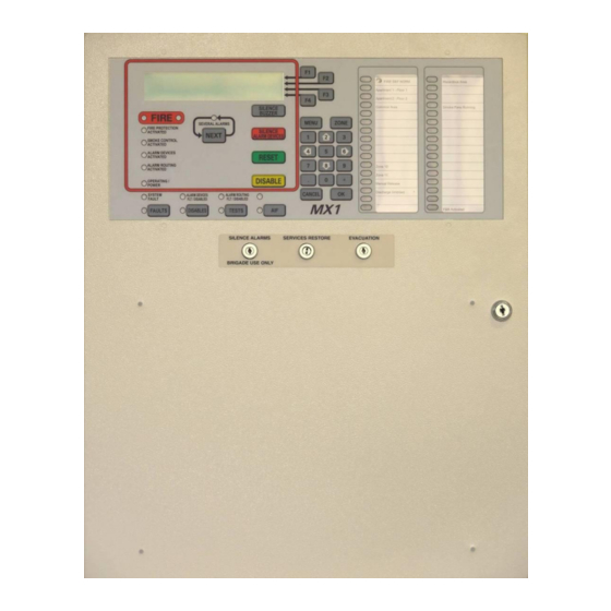
- Page 24 An MX1 Operator Manual (LT0344) is supplied with each MX1. This manual describes how to use the alphanumeric display and keypad on the front of the MX1 to view the status of the system and to perform basic service functions.
- Page 25 8 remote display devices using proprietary RZDU protocol. SGD Interface 10 way FRC header suitable for connection to VIGILANT® GP SGD (PA0862) or GP Brigade Interfaces Brigade Relay Interface (PA0861). ASE Interface...
- Page 26 Installation Guide MX1 Fire Alarm System (NZ) Manufactured Johnson Controls 17 Mary Muller Drive, PO Box 19-545 Christchurch 8022, New Zealand +64-3-389 5096 +64-3-389-5938 LT0360 ISSUE 2.43 29 NOVEMBER 2017 PAGE 26...
Need help?
Do you have a question about the MX1 and is the answer not in the manual?
Questions and answers