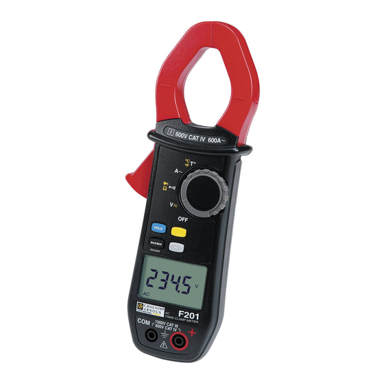
Chauvin Arnoux F201 User Manual
Clamp multimeter
Hide thumbs
Also See for F201:
- Start manual (65 pages) ,
- Quick start manual (65 pages) ,
- User manual (36 pages)
Table of Contents
Advertisement
Quick Links
Advertisement
Table of Contents

Related Manuals for Chauvin Arnoux F201


Summary of Contents for Chauvin Arnoux F201
- Page 1 CLAMP MULTIMETER F201 E N G L ISH User’s manual...
-
Page 2: Table Of Contents
Clamp Multimeter F201 English CONTENTS PRESENTATION......................7 THE SWITCH ......................... 8 THE KEYS OF THE KEYPAD..................9 THE DISPLAY UNIT....................10 1.3.1 The symbols of the display unit ..............10 1.3.2 Measurement capacity exceeded (O.L) ............11 THE TERMINALS ....................... 11 THE KEYS......................... - Page 3 English Clamp Multimeter F201 3.11 FREQUENCY MEASUREMENT (H ) ..............23 3.11.1 Frequency measurement in voltage ............. 23 3.11.2 Frequency measurement in current ............. 24 3.12 TEMPERATURE MEASUREMENT ................. 25 3.12.1 Measurement without external sensor............25 3.12.2 Measurement with external sensor............... 25 CHARACTERISTICS ....................
- Page 4 Clamp Multimeter F201 English You have just acquired an F201 clamp multimeter and we thank you. For best results from your device : read this user manual attentively, observe the precautions for its use. Meanings of the symbols used on the device Danger.
- Page 5 English Clamp Multimeter F201 PRECAUTIONS FOR USE This device complies with safety standards IEC-61010-1 and 61010-2-032 for voltages of 1000V in category III or 600V in category IV at an altitude OF less than 2000m, indoors, with a degree of pollution not exceeding 2.
- Page 6 Clamp Multimeter F201 English When handling the test probes, crocodile clips, and clamp ammeters, keep your fingers behind the physical guard. As a safety measure, and to avoid repeated overloads on the inputs of the device, we recommend performing configuration operations only when the device is disconnected from all dangerous voltages.
-
Page 7: Presentation
English Clamp Multimeter F201 1 PRESENTATION The F201 is a professional electrical measuring instrument that combines the following functions: Current measurement; Measurement of inrush current / overcurrent (True-Inrush); Voltage measurement; Frequency measurement; Continuity test with buzzer;... -
Page 8: The Switch
Clamp Multimeter F201 English THE SWITCH The switch has five positions. To access the , functions, set the switch to the desired function. Each setting is confirmed by an audible signal. The functions are described in the table below. Figure 2 : the switch... -
Page 9: The Keys Of The Keypad
English Clamp Multimeter F201 THE KEYS OF THE KEYPAD Here are the four keys of the keypad : Figure 3 : the keys of the keypad Item Function See § Storage of values, disabling of display Compensation of the resistance of the leads in the 3.6.1... -
Page 10: The Display Unit
Clamp Multimeter F201 English THE DISPLAY UNIT Here is the display unit of the clamp multimeter: Figure 4 : the display unit Item Function See § Display of the modes selected (keys) Display of the measurement value and unit 3.12... -
Page 11: Measurement Capacity Exceeded (O.l)
English Clamp Multimeter F201 Hertz Ampere Ω Milli- prefix Kilo- prefix Compensation of the resistance of the leads Continuity test Diode test Permanent display (automatic switching off de-activated) Spent battery indicator 1.3.2 Measurement capacity exceeded (O.L) The O.L (Over Load) symbol is displayed when the display capacity is exceeded. -
Page 12: The Keys
Clamp Multimeter F201 English 2 THE KEYS The keys of the keypad respond differently to short, long, and sustained presses. In this section, the icon represents the possible positions of the switch for which the key concerned has some action. -
Page 13: Key
English Clamp Multimeter F201 Remark: the key is invalid in the MAX/MIN and HOLD modes. Successive … serve presses on -to select AC or DC. Depending on your choice, the screen displays AC or DC -to cycle through the and diode test modes and to return to the continuity test -to select °C or °F as the unit... -
Page 14: The Max/Min Mode + Activation Of The Hold Mode
Clamp Multimeter F201 English 2.3.2 The MAX/MIN mode + activation of the HOLD mode Successive presses on … serve display successively MAX/ short MIN values detected before the was pressed Note: the HOLD function does not interrupt the acquisition of new MAX, MIN values 2.3.3... -
Page 15: Key
English Clamp Multimeter F201 This key is used to display the frequency measurements of a signal. Remark : this key is not working in DC mode. 2.4.1 The Hz function in the normal model Successive …serves presses on to display:... -
Page 16: Use
Clamp Multimeter F201 English 3 USE COMMISSIONING Insert the battery supplied with the device as follows: Using a screwdriver, unscrew the screw of the battery compartment cover (item 1) on the back of the housing and open it. Place the battery in the compartment (item 2), taking care to get the polarities right. -
Page 17: Configuration
English Clamp Multimeter F201 CONFIGURATION As a safety measure, and to avoid repeated overloads on the inputs of the device, we recommend performing configuration operations only when the device is disconnected from all dangerous voltages. 3.4.1 Programming of the maximum resistance allowed for a... -
Page 18: Programming Of The Current Threshold For The True Inrush Measurement
Clamp Multimeter F201 English 3.4.3 Programming of the current threshold for the True INRUSH measurement To program the triggering current threshold of the True INRUSH measurement: 1. in the OFF position, hold the key down while turning the switch to , until the "full screen"... -
Page 19: Default Configuration
English Clamp Multimeter F201 3.4.5 Default configuration To reset the clamp to its default parameters (factory configuration): In the OFF position, hold the key down while turning the switch to until the "full screen" display ends and a beep is emitted, to enter the configuration mode. -
Page 20: Continuity Test
Clamp Multimeter F201 English CONTINUITY TEST Warning : Before performing the test, make sure that the circuit is off and any capacitors have been discharged. Set the switch to ; the symbol is displayed ; Connect the black lead to the COM terminal and the red lead to «+». -
Page 21: Resistance Measurement
English Clamp Multimeter F201 RESISTANCE MEASUREMENT Warning : Before making a resistance measurement, make sure that the circuit is cold and any capacitors have been discharged. key. The symbol is Set the switch to and press the displayed;... -
Page 22: Current Measurement (A)
Clamp Multimeter F201 English The measured value is displayed on the screen. CURRENT MEASUREMENT (A) The jaws are opened by pressing the trigger on the body of the device. The arrow on the jaws of the clamp (see the diagram below) must point in the presumed direction of flow of the current, from the generator to the load. -
Page 23: Starting Current Or Overcurrent (True Inrush) Measurement
English Clamp Multimeter F201 3.10 STARTING CURRENT OR OVERCURRENT (TRUE INRUSH) MEASUREMENT To measure a starting True-Inrush current, proceed as follows: Set the switch to then encircle only the conductor concerned with the clamp. Effect a long press on the key. -
Page 24: Frequency Measurement In Current
Clamp Multimeter F201 English The measured value is displayed on the screen. 3.11.2 Frequency measurement in current Set the switch to and press the key. The Hz symbol is displayed. Encircle only the conductor concerned with the clamp. The measured value is displayed on the screen. -
Page 25: Temperature Measurement
English Clamp Multimeter F201 3.12 TEMPERATURE MEASUREMENT 3.12.1 Measurement without external sensor Set the switch to The temperature displayed (blinking) is the internal temperature of the device, equal to the ambient temperature after a sufficiently long thermal stabilization time (at least one hour). -
Page 26: Characteristics
Clamp Multimeter F201 English 4 CHARACTERISTICS REFERENCE CONDITIONS Quantities of influence Reference conditions Temperature: 23°C ±2°C Relative humidity: 45% to 75% Supply voltage: 9.0V ±0.5V Frequency range of the applied signal: 45–65Hz Sine wave: pure Peak factor of the applied alternating signal: √2... -
Page 27: Ac Voltage Measurement
English Clamp Multimeter F201 Note (1) Above 1000V, a repetitive beep indicates that the voltage being measured is greater than the safety voltage for which the device is guaranteed. The display indicates "OL" 4.2.2 AC voltage measurement Measurement 0.15 V to 60.0 V to... -
Page 28: True-Inrush Measurement
Clamp Multimeter F201 English Note (1) Above 600 A, the display indicate “OL”. The bandwidth is 3 kHz in AC Note (2) Any value between zero and the min. threshold of the measurement range (0.15V) is forced to “----“ on the display. -
Page 29: Diode Test
English Clamp Multimeter F201 Note (1) Above the maximum display value, the display unit indicates "OL". - The "-" and "+" signs are not managed. Specific characteristics in MAX/MIN mode: Uncertainties: add 1% R to the values of the table above. -
Page 30: Temperature Measurement
Clamp Multimeter F201 English Specific characteristics in MAX/MIN mode MAX-MIN (from 10Hz to 1kHz): Uncertainties: add 1% R to the values of the table above. Capture time of the extrema: approximately 100ms. 4.2.9 Temperature measurement Function External temperature... -
Page 31: Characteristics Of Construction
English Clamp Multimeter F201 CHARACTERISTICS OF CONSTRUCTION Housing: Rigid polycarbonate shell with moulded elastomer covering Polycarbonate Jaws: Opening: 34 mm Clamping diameter: 34 mm LCD display unit Screen: Dimension: 28 x 43.5 mm Dimension: H-222 x W-78 x D-42 mm... -
Page 32: Variations In The Domain Of Use
Clamp Multimeter F201 English VARIATIONS IN THE DOMAIN OF USE Influence Quantity of Range of Quantity influence influence influenced Typical V AC 0,1%R/10°C V DC 0,1%R/10°C 0,5%R/10°C + 2 ct Temperature -20...+55°C 1%R/10°C 1,5%R/10°C + 2ct T°C (0,2%R+1°C)/10°C (0,3%R+2°C)/10°C 0,1%R/10°C + 2ct Hz ... -
Page 33: Maintenance
This instrument should be checked at least once a year. For checks and calibrations, contact one of our accredited metrology laboratories (information and contact details available on request), at our Chauvin Arnoux subsidiary or the branch in your country. REPAIR For all repairs before or after expiry of warranty, please return the device to your distributor. -
Page 34: Warranty
Damage caused by shocks, falls, or floods. 7 DELIVERY CONDITION The F201 clamp multimeter is delivered in its packaging box with : 2 banana-test probes leads, one red and one black ... - Page 35 Tel: +86 21 65 21 51 96 - Fax: +86 21 65 21 61 07 SCANDINAVIA - CA Mätsystem AB USA - Chauvin Arnoux Inc - d.b.a AEMC Instruments Box 4501 - SE 18304 TÄBY 200 Foxborough Blvd. - Foxborough - MA 02035...
Need help?
Do you have a question about the F201 and is the answer not in the manual?
Questions and answers