Table of Contents
Advertisement
Advertisement
Table of Contents

Related Manuals for Wilesco D100E


Summary of Contents for Wilesco D100E
- Page 1 Steambox D 100 E E-Box E 50...
- Page 3 Steambox D 100E and E-Box E50 Wilhelm Schröder GmbH & Co. KG D-58511 LÜDENSCHEID Schützenstraße 12 phone : +49 - 2351 - 9847-0 e-mail : info@wilesco.de...
- Page 4 Imprint: This is a publication from Wilesco©, Wilhelm Schröder GmbH & Co KG, D-58511 LÜDENSCHEID. All rights including translation are reserved. Any reproduction, f. ex. photo copies, microfilming, electronic data processing need a written permission of the author. Prints, also only parts, are forbidden.
- Page 5 With this Steam Box or the E–Box 50 in combination with a steam engine model and the booklet one can experience practically how the steam engine and the transformation into electricity functions. Wilesco has joined for you all the needed components in the Steam Box D 100E and the E-Box 50.
-
Page 7: Table Of Contents
Inhaltsverzeichnis 1. BASICS ABOUT THE STEAM ENGINE........... 9 1.1 THE STEAM ENGINE AND ITS DEVELOPMENT....... 9 1.2 KNOWLEDGE ABOUT THE STEAM ENGINE......10 1.2.1 How to change water into steam ..........10 1.2.2 The boiler.................. 11 1.2.3 The flywheel................11 1.2.4 The oscillating steam engine ............ - Page 8 3.2 FROM THE MECHANIC ENERGY TO THE ELECTRIC ENERGY....................41 3.2.1 Connection and function of the current machine ..... 41 3.3 FIRST EXPERIMENTS WITH THE GENERATOR ..... 42 3.4 ROTATION DIRECTION INDICATOR ........43 3.4.1 The transfer of the circuit ............43 3.4.2 The technical and the real current direction......
-
Page 9: Basics About The Steam Engine
1. Basics about the steam engine Steam engines are heat engines and they work in contrary to the combustion motors without inner combustion. Mechanical energy is provided through the pressure of the steam. One can use different sources of heat to make the engine work;... -
Page 10: Knowledge About The Steam Engine
At that time the steam engine brought a lot of possibilities in the areas of transport and construction. From the first rotation on the engine brings a high torque to the axis and is able to work forwards and backwards. Steam automobiles can start moving under load and do not need clutch and gearing. -
Page 11: The Boiler
Keeping the arising steam in a closed vessel will produce a very high pressure, which can even lead to an explosion of the boiler. Therefore the steam engines have safety valves which open with high pressure so the steam can escape. One uses the pressure of the steam by moving a piston in a cylinder, which produces mechanical energy. - Page 12 Fig. 1.01: The oscillating cylinder: steam engine model of the steam box On the back of the cylinder we find a hole which is called steam hole. On the connected surface of the fixing bracket we find a steam supplying hole and a steam exhausting hole.
-
Page 13: The Valve-Controlled Steam Engine
Contrary to these simple constructions there are also valve-controlled models available, such as the steam engine model D9/D10, D20 and other models from Wilesco. The valve-controlled steam engine works like this: Water steam provided by the boiler enters the slide box and a slider presses on one side of the piston within the cylinder. -
Page 14: Power An Efficiency
1.3 Power and efficiency One of the real advantages of the steam engine is that through the external combustion he does not depend on high quality fuel. He works with any kind of fuel, f. ex. coal, wood, oil, peat, any kind of waste etc. This is not true for the steam engine model, they are fed with dry spirit tablets. -
Page 15: What Function Has The Steam Engine Nowadays
Beside the different technical structures both models also differ in power transfer and efficiency. For the same amount of power the Steam Box model needs more fuel then the D 20 model. The generator is excellent to explore the power transfer. 1.4 What function has the steam engine nowadays? In the area of the power engines the steam engine was substituted through the combustion engine. - Page 16 winter season. A combined heat and power production serves well, mainly for the heating season. Systems like this provide f. ex. for private households or internal consumers, an all year round and energy self- sufficient concept. Instead of the steam engine one also can use a Stirling engine. Both constructions can work with all kinds of solid and liquid fuels, f.
-
Page 17: Assembling The Model
This allows injecting the steam engine oil well measured onto the oil needing parts. Do not use any liquid oil for lubricating the piston and cylinder. Please only use Wilesco steam engine oil. -
Page 18: Assembly Instructions Step By Step
Fig. 2.02: Lubricating with a disposable syringe Before lightening the dry spirit tablets check whether the burner slide moves easily in and out of the burner slide box (in the boiler house of the steam engine model). If not you can slightly widen the sides of the burner slide box. -
Page 19: Step 3: Assembling And Mounting The Flywheel
Step 2: Mounting the burner slide and boiler house CAUTION work carefully because of sharp edges! Insert the tabs on the burner slide (5) with the point facing towards the front into the corresponding slots on the base plate (1). Turn the base plate (1) over, and tap the burner slide tabs outwards, using the screwdriver handle. -
Page 20: Step 4: Assembling The Cylinder Unit
Fig.2.2.3: mounting the flywheel Step 4: Assembling the cylinder unit. Mount the cylinder unit first by fitting the spring (18) and the baffle plate (15) onto the screw M3x16 (17). Now tighten her into the threaded hole on the cylinder (20) by turning the screw only 1-2 times. Do not turn further otherwise this will damage the cylinder. -
Page 21: Step 5: Mounting The Steam Pipe, Chimney And Final Assembly
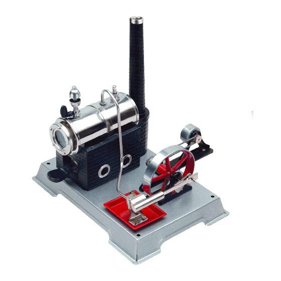
Step 5: Mounting the steam pipe, chimney and final assembly On the boiler are three threaded holes. Put a gasket (26) into the middle one and in the threaded bush on the baffle plate (15). Slide the cover (14) over the packing screw (13-1) on the baffle plate end of the steam pipe (13) and lightly ( first by hand) screw both ends of the steam pipe into the gasketed holes. - Page 22 Fig 2.3.1: A complete steam engine model without generator Before operating read the instructions carefully. We wish you lots of fun in building and operating this steam engine.
-
Page 23: Precaution Instructions
Important! Never operate the engine without safety valve. Only use WILESCO steam engine oil and dry fuel tablets! Each irregularity during operation has to be repaired by a competent and authorized person or by WILESCO themselves. - Page 24 If the boiler or any steam leading part leak, stop the steam model immediately by removing the burner slide. Any necessary repair should be carried out by authorized staff or at the WILESCO company. The steam engine meets all safety standards and actual regulations.
-
Page 25: Preparation For The First Test Run
2-3 drops of Wilesco steam engine oil onto the piston and abt. 2-3 drops into the cylinder itself. 2-3 drops oil are sufficient for approx. 10 minutes operating time. - Page 26 because of the risk of danger from an open flame, always take the necessary safety precautions. The burner slide is adjustable. The oxygen supply and the flame height can be adjusted by moving the burner slide in relation to the air holes of the burner slide guide in the boiler housing.
- Page 27 Fig.2.3.2: Steam engine of the Steam Box with generator...
-
Page 29: Experiments With The Steam Engine And
Experiments with steam engine additional components Together with the added components and the steam model one now can start to build electrical and electronic circuits. 3.1 The components and their description Here are described the qualities and the use of the added components in the Steam Box D 100E and the E-Box 50 3.1.1 The generator You find a permanently excited current machine in the Steam Box D 100E... -
Page 30: Transmission Belt
Fig.3.0.2: direct current machine with mounting support The connecting cables (red/black) are made out of flexible strand and can be connected f. ex. with crocodile clips with the bread board. 3.1.2 Transmission belt Through twisting the enclosed transmission belt it is joined together or pulled apart. -
Page 31: The Bread Board
3.1.3 The bread board The bread board, also called patch panel, consists in his inside contact springs, which are connected to one another in a system of rows. The bread board is excellent for realizing electronic circuits in combination with the steam engine. The electronic parts, such as the LEDs, resistances and connecting wires can be repeatedly used and inserted into the contacts. - Page 32 When the bread board is new, initially it can be difficult to stick in the pieces and wire jumpers. It helps to prepare the contacts with a thin needle, which should not be thicker then 0,3 – 0,6 mm, otherwise the contact spring wears out to an extend that the contacts to the wire connection might suffer.
-
Page 33: Leds
Fig.3.07: bread board glued to a mounting board (mounting board not included) 3.1.5 LEDs Compared to a normal diode the LED (light emitting diode) has one further characteristic! It shines when voltage is applied. You find a red, an orange, 2 white shining LEDS and a red flashing LED. -
Page 34: Electrolytic (Electrolytic Capacitors)
In some experiments together with the generator are series resistors with 100 Ohm to 1K-Ohm recommended. Compared to the normal light bulb the LED does not have a filament. They have a long durability and do not consume a lot of energy. Fig.3.09: The connections of the LED: the longer end of the wire is the cathode, the “negative connection”, also marked through a flattened... - Page 35 negative pole. When it is connected “the wrong way around” over a longer period, the electrolyte of the capacitor will be destroyed. Do not exceed the imprinted maximum voltage indication, because otherwise the insulation layer can be destroyed. Enclosed you find radial electrolytic capacitors with the following capacities: 1000µF and 4700µF Fig.3.11: circuit symbol, electrolytic capacitors, left the positive pole...
-
Page 36: Diode
3.1.7 Diode Diodes let the current pass in only one direction. For that reason, they are used to rectify AC voltages and to block undesirable polarity with DC voltage, among other things. You can picture the functioning of a diode in normal operation most easily as a non-return valve (water installations). -
Page 37: Resistors
3.1.8 Resistors A resistor is a passive component in electric and electronic circuits. Its main task is the reduction of the flowing current to “reasonable” values. The most famous resistors are the cylindrical ceramic type with axial connection wires. The resistance values are imprinted in the form of coded coloured rings. -
Page 38: Crocodile Clips (Red/Black)
3.1.9 Crocodile clips (red/black) With the red and black experimental wires, which have the crocodile clips on their ends, you can easy and fast connect and combine different electric parts (without soldering). It makes sense to use the red wire for the positive pole, the black one for the negative pole. -
Page 39: Switch
3.1.11 Switch According to the figure you find one switch. This type with 2 connections is suitable for the use on the bread board. The electric flow is as long established as the switch is pressed. Letting go of the switch is stopping the flow again. - Page 40 Components in an overview: amount type detail generator, permanent excited, current machine generator bracket bread board 170 contacts switch LED, red 5 mm LED, orange 5 mm LED, white, extra bright 5 mm mind. 2500 mcd flash-LED, red 5 mm electrolytic 1000µ, 10 V (or higher)
-
Page 41: From The Mechanic Energy To The Electric Energy
3.2 From the mechanic energy to the electric energy To gain electricity out of steam we need a couple of steps. First happens the transformation from steam energy into mechanical energy and then from mechanical energy into electricity. In our day to day life electricity has the advantage that we can already use the existing installation and its use is universal. -
Page 42: First Experiments With The Generator
connection cable towards the insulation and then stick all into the clip. This connection can maintain like this in most of the following experiments. Fig.3.20:a) connection of generator cable and crocodile clips, b) detail, how to put in the cable to provide a stable contact. Do not connect the generator to the steam engine for the first experiments! 3.3 First experiments with the generator Components like before, 1 orange LED added... -
Page 43: Rotation Direction Indicator
Fig.3.21: a) assembly of the experiment and b) circuit diagram Note: The orders of the experiments build up on each other. You do not have to dismount everything after each experiment, but parts can be joined, taken away or changed. 3.4 Rotation direction indicator With this circuit you can construct a rotation direction indicator. - Page 44 Fig.3.22a) The first circuit diagram, G for generator, R1 for series resistor, D1 for the orange LED and D3 for the red LED The electronic components such as resistor R1 or the D1 orange LED or the D3 red LED can be plugged into the bread board without soldering. Through the internal connections of the contacts of the bread board and the added jumpers` one gains the electronic circuit and the electrical circuit.
- Page 45 In Fig.3.22b) one can see the connections and also the structure of the LEDs within its enclosure. The cathode has a shorter connection wire and the metal end within the transparent enclosure has the shape of a triangle. In the figure you can see how the LEDs are plugged into the bread board.
-
Page 46: The Technical And The Real Current Direction
3.4.2 The technical and the real current direction In which direction do the electrons flow within an electric circuit? Information about technical and real current direction: Observing the flow of the electrons (f. ex. with the electrolysis), one can see that the electrons really flow from the negative pole to the positive pole. -
Page 47: Mounting The Generator
To mount the generator on the basic plate of the steam machine one uses a two-piece compression fitting in combination with the generator mounting support. You can install the generator to almost all basic plates of the Wilesco steam engine models. Depending on the type of the steam engine model they produce rotations from 1000-2000R/min at the axis of the flywheel. -
Page 48: Generator, To Connect Mechanically With The Flywheel Of The Steam Engine
Position the lower part underneath the basic plate and the upper part above and connect together with the generator mounting support/ generator with two screws and nuts. Before tightening the screws, adjust the holder of the generator that both pulley wheels – that of the generator and that of the flywheel of the steam engine –... -
Page 49: Measuring The Voltage Of The Generator
Fig.3.28: The right tension of the belt is important for a successful work! The right tension of the belt helps that the transmission of the mechanical energy to the generator flows optimally and without gaps and at the same time as less loss as possible through friction occurs. Is the belt too tight, it is hard for the steam engine to move the generator and he can not establish the appropriate rotational speed. - Page 50 Fig.3.29: measuring the voltage of the generator with a multimeter Fig.3.30: Symbols of the circuit diagram, left the symbol for the generator, right the symbol for the measuring instrument...
-
Page 51: The Direction Of The Rotation Of The Steam Engine And The Generator
Note: Please do not put the bread board with the electronic circuits too close to the steam outlet (cylinder). Use the cables with the crocodile clips and put the board with the electrical circuits in an appropriate distant to the steam engine and continue doing your experiments. Fig.3.31 appropriate place for the bread board The voltage is depending on the maximal possible rotational speed of the... -
Page 52: Using Steam Energy To Generate Electricity
3.6 Using steam energy to generate electricity We need a generator to generate electricity out of steam. The word “generator” has its origins in the Latin language and means freely translated “to bring out” or “to produce”. Though looking more exactly, energy can not be produced, only changed from one state into a different one. - Page 53 Here you find once more the colours and values of the resistors listed and the sequence of their use within the experiment. Value of the 1. ring 2. ring 3. ring 4. ring resistor 1000 Ohm Brown black Gold 100 Ohm Brown black brown...
- Page 54 Observations while testing, in connection with the steam engine model of the Steam Box D 100E: One can not observe almost any change when the 1K resistor is installed. The additional need of electricity is only about a couple mA. When you plug in the following resistor of 100 Ohm you recognize that the orange LED starts to flicker and the rotation of the steam engine model slows down.
-
Page 55: Step By Step Generating Bright Light Out Of Steam
Fig.3.35: Two different steam engine models and their different power capacities. Steam Box D 100E and D20 in comparison The steam engine model of the Steam Box D 100E and of the D20 are two extremely different models, also in their powers. The experiments with the resistors show that a bigger steam engine model has no problems with an additional need of electricity. - Page 56 Fig.3.36: Light through steam, the circuit. You see the series resistor (above on the right side), the jumpers` and the white LED (below on the right side), the longer connection wire (+) of the LED on the right side Prepare the steam engine model as described in chapter 2.4. The pulley wheel of the generator and the steam engine model are connected with the transmission belt.
- Page 57 Especially with the smaller steam engine models one can observe that the rotational speed of the steam engine slows down and the white LED starts to shine. The LED shines bright when the rotational speed has stabilized, probably still with a little pulsating or flashing. Measuring the initial voltage with an oscilloscope (a professional instrument to show the voltage in a graphical diagram) would show us a wave, caused by the continuous interruptions of the commutator of the generator.
-
Page 58: More Light With 2 White Leds
Fig.3.39: circuit diagram, both electrolytic are marked in with an arrow to show that they are used alternatively The light of the LED goes out shortly and then starts to flash a little less bright after plugging in the electrolytic 1000µF. Now you replace the electrolytic 1000µF with the 4700µF in the next step and a calm light will shine. -
Page 59: Light From Four Leds Generated Throught The Steam Engine
Fig.3.40: Assembly of the bread board with a second white Led parallel to the first white LED. Both LEDs have the connection wire (+) on the right side Fig.3.41: circuit diagram with two LEDs, here the electrolytic can also be used alternatively 3.7.2 Light from four LEDs generated through the steam engine All LEDs (except the flashing one) are in use and one can observe how... - Page 60 Here you have an overview of the series resistors for the LEDs: Value of the 1. ring 2. ring 3. ring 4. ring resistor 1 K-Ohm brown black gold 100 Ohm brown black brown gold Fig.3.42: Assembly of the bread board and b) detail of the assembly (a picture taken from the other side) Fig.3.43: circuit diagram with more LEDs Note: When the steam engine is decelerating one can try to slow down the...
-
Page 61: Storage Of The Electric Energy
3.8 Storage of the electric energy We explore in this experiment whether the energy generated by the steam engine can be stored. Picturing the process of storage as followed: Again we take the example of the water bucket. Now the hole on the bottom of the bucket is replaced through a crane. - Page 62 Assembly of the experiment: generator, bread board, one red and one black cable with crocodile clips, orange LED, series resistor 1 K-Ohm (red, black, brown, gold), 2x electrolytic 4700µF Fig.3.45: a) circuit of charge and b) with one electrolytic and LEDs as charge- respectively consumption indicator Steps of the experiment: Mount the circuit according to the figure, circuit diagram.
- Page 63 Fig.3.47: circuit of charge with two electrolytic and one LED as charge- and consumption indicator One can repeat those experiments, this time with an additional electrolytic plugged in parallel. The steam engine charges simultaneously both electrolytic through the generator. Fig.3.48: circuit diagram with 2 electrolytic and one LED as a charge-...
-
Page 64: Diode Blocking Discharge, Schottkydiode
3.8.2 Diode blocking discharge, Schottkydiode Components: like before, additional one Schottkydiode BAT 48 As you could observe in the former experiments, the stored energy of the electrolytic is discharged backwards into the generator. It is important to install a blockage for the current not to flow backwards, like a diode when charging an energy storage f. - Page 65 Fig.3.49: Assembly of the experiment, b) detail: mounting of the diode, the black ring (cathode) is on the left side of the picture This experiment shows that the electrolytic is charged by the generator, is keeping the voltage and storing it. Fig.3.50: circuit diagram: discharge protection diode You can measure the voltage which is stored in the electrolytic with a multimeter.
-
Page 66: Charge Indicator For The Electrolytic
Fig.3.51: Measuring the voltage with a multimeter, you can see the cables of the multimeter (in the lower part of the picture on the left) connected to the electrolytic connection cable. The following questions come up while charging the storage: is he empty, half full or full? If you have a multimeter you easily can find out by measuring the voltage of the input. - Page 67 Fig.3.52: Charge indicator with the flash LED, assembly of the circuit on the bread board Fig.3.53: circuit diagram of the charge indicator Please make sure that the electrolytic is empty before starting the experiment; f. ex. join both connection cables of the electrolytic through a screwdriver.
- Page 68 With this assembly and the running steam engine you can continue to explore more experiments, like f. ex.: Disconnect for a short time the red crocodile clip next to the diode from the pin, wait and then connect again. ...
-
Page 69: Using Stored Energy
3.8.4 Using stored energy Assembly of the experiment: the circuit of the former experiment will be slightly changed. Take out the LEDs and the series resistors, plug in the pin of the positive pole on the very right of the bread board and put in the schottkydiode so that she is parallel connected to the switch. -
Page 70: The Steam Engine As A Charging Station For The Torch
Fig.3.58: measuring the voltage of the electrolytic with a multimeter 3.8.5 The steam engine as a charging station for the torch. Assembly of the experiment: we use the assembly of the second last experiment. We plug in two white LEDs instead of the orange LED. You can disconnect the crocodile clips after a short charging period through the steam engine and generator. - Page 71 Fig.3.59: Charging station, LED with the steam engine model Fig.3.60: Assembly of the bread board, with two parallel plugged in electrolytic 4700µF, Schottkydiode, switch, two white LEDs and jumpers`...
- Page 72 Fig.3.61: circuit diagram of the charging station Fig.3.62: disconnected “LED torch” in action One can create a lot more experiments with the Steam Box D 100E and with the E-Box 50. I wish you a lot of fun and creativity!
-
Page 73: Annex
4. Annex 4.1 Collection of the formularies Here you find some formularies for basic circuits we have been applying and exploring in the experiments. 4.1.1 Voltage, current and resistance The most important values of the electronic technique are voltage, current and resistance, gathered in the law of Ohm with the following symbols and values. -
Page 74: Parallel Circuit Of Resistors
And resistance = voltage/ current; or as a formulary: 4.1.2 Parallel circuit of resistors When connecting two resistors R1 and R2 parallel the following total resistance R results: R = (R1 x R2) / (R1 + R2) Example: Resistance R1 = 1 k-Ohm parallel to the resistor R2 = 100 Ohm Calculated total resistance R = (1 x 100) / (1 + 0,1) = 99,9 Ohm The total resistance becomes less. -
Page 75: Series Connection Of Resistors
4.1.3 Series connection of resistors When you connect resistors one after the other in a row, you add the values of R1 and R2 to the total resistance: R = R1 + R2 Example: Resistance R1 = 100 Ohm and resistance R2 = 1 k-Ohm Calculated total resistance: R = 100 Ohm + 1 k-Ohm = 1100 Ohm R = total Fig.4.02 series connection of two... -
Page 76: The Steam Engine
4.2.1 The steam engine In general the smoothness and the leak tightness of a steam engine model do not influence the basic function. Never the less it is important that the steam engine runs easy and smooth. For all models and as well for the steam engine model counts: the smoother they run the better they function. -
Page 77: Supplier Sources For Spare Parts And Electronic Parts
May be one part is still missing? 4.3 Supplier sources for spare parts and electronic parts Consumables (see below and others) and spare parts for steam engines are available through Wilesco distributors or: www.sell-it-easy.de (info@sell- it-easy.de). Electronic parts are available for example with www.conrad.de 4.3.1 Consumables for steam engines... -
Page 78: Warranty
All WILESCO Steam Engines are carefully checked before leaving the factory. However if a problem arises, you can return the Steam Engine to a specialized distributor or directly to WILESCO. We are sure you will understand that already fired or used models cannot be exchanged for new ones. - Page 79 The qualified internetshop - The complete Wilesco range on stock The classic steam roller D365 Steam engine D21 Sell-it-easy IH GmbH Schützenstraße 12 D-58511 Lüdenscheid Germany phone: +49 2351-984780 fax: +49 2351-984781 info@sell-it-easy.de Dry-spirit tablets www.sell-it-easy.de...
Need help?
Do you have a question about the D100E and is the answer not in the manual?
Questions and answers