Table of Contents
Advertisement
Quick Links
Advertisement
Table of Contents

Related Manuals for Time Electronics 1044


Summary of Contents for Time Electronics 1044
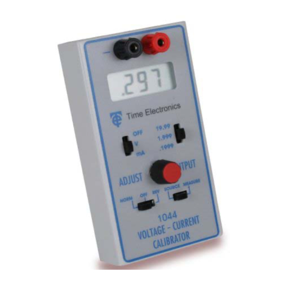
- Page 1 Time Electronics 1044 Voltage and Current Calibrator Technical Manual V1.1 09/01/11 Time Electronics Ltd Botany Industrial Estate, Tonbridge, Kent, TN9 1RH Tel: +44(0)1732 355993 Fax: +44(0)1732 770312 Email: mail@TimeElectronics.co.uk Web Site: www.TimeElectronics.com...
-
Page 2: Table Of Contents
Manuel T ec hnique (F ranc ais ) ................. 14 T ec hnis c hes Handbuc h (Deuts c h)................. 28 All Time Electronics' instruments are subject to continuous development and improvement and in consequence may incorporate minor detail changes from the information contained herein. -
Page 3: Introduc Tion
1. Introduc tion The 1044 has been designed to offer solutions in many applications from the R&D lab to the service engineer; in fact anywhere an accurate and low cost calibrator is needed. We have used our experience in designing instrumentation to bring you the most versatile and practical calibrator yet. -
Page 4: S Pec Ific Ations
± 3 Counts Current Measure Range Resolution Accuracy Impedance T/C per °C 0 - 200uA 100nA ± 0.05% 10Ω ± 200ppm 0 - 2mA 0 - 20mA 10uA ± 3 Counts V1.1 09/01/11 P a g e 1044 Technical Manual... - Page 5 12V power supply can be plugged into the 2.5mm socket located on the end of the unit, the tip of the plug should be positive. PROTECTION The 1044 can withstand open circuits, short circuits and reverse polarity up to 25V. Additional protection is by an 20mm F100mA internal fuse. CONSTRUCTION Construction is in a durable plastic case with sliding cover for battery storage.
-
Page 6: Operation Of The 1044
3. Operation of the 1044 CONTROLS All the operator controls are located on the front panel with calibration adjustments located inside the unit along with the input/output protection fuse. Refer to the Fault Diagnosis section for more information. V1.1 09/01/11... -
Page 7: Preliminary
Always check the mode of operation and range values before connecting to the unit under test or to the circuit being measured. If the 1044 will not source or measure the protection fuse has probably blown due to an excessive current being applied to the unit. This can be found inside the 1044 - refer to section 7, page 12 for more details. -
Page 8: Measuring A Voltage Input
The reading should now be displayed. If the display shows the digit 1 with a blank character then the unit has over-ranged and must be switched to the next highest range. V1.1 09/01/11 P a g e 1044 Technical Manual... -
Page 9: Operation Of The 4-20Ma S Ys Tem
4. Operation of the 4-20mA S ys tem Introduction A common use of the 1044 would be to simulate a transducer or measure the current flow in a transducer loop. The following brief explanation, which is intended as a guideline only, may help when operating the 1044 in a 4-20mA system. -
Page 10: B Attery R Eplac Ement
2.5mm jack socket at the end of the instrument. This will cut out the internal battery and power the 1044. Note that the tip of the 2.5mm jack plug should be positive. The 1044 is protected against reverse polarity and will not function in this state. -
Page 11: R Ec Alibration
1) Locate the 200mV trimmer pot on the rear of the LCD display. This can be reached via a hole in the PCB. Set the 1044 to the 200mV range and adjust the trimmer to give 200mV. 2) Locate VR7 - 20V adjust. Select the 20V range and adjust VR7 for reading of 20V. -
Page 12: F Ault Diagnos Tic S
The value selected on the display drops when the unit under test is connected. This is a feature of the 1044 where the ‘actual’ value is indicated. This is probably insufficient current drive from the 1044 because the unit under test is loading the output beyond its 20mA drive capability. -
Page 13: G Uarantee & S Ervic Ing
We maintain comprehensive after sales facilities and the unit can, if necessary be returned to us for servicing. During this period, Time Electronics Ltd will, at its discretion, repair or replace the defective items. For servicing under guarantee, the instrument type and serial number must always be quoted, together with details of any fault and the service required.
Need help?
Do you have a question about the 1044 and is the answer not in the manual?
Questions and answers