Table of Contents
Advertisement
Quick Links
Advertisement
Table of Contents

Related Manuals for Time Electronics 7006


Summary of Contents for Time Electronics 7006
- Page 1 User Manual 7006 Loop-Mate 1 Loop/Current/Voltage Simulator Version 1.1 March 2021 Time Electronics Ltd Unit 5, TON Business Park, 2-8 Morley Road, Tonbridge, Kent, TN9 1RA, United Kingdom. T: +44 (0) 1732 355993 | F: +44 (0) 1732 350198 mail@timeelectronics.co.uk | www.timeelectronics.com...
- Page 2 All rights reserved. Nothing from this manual may be multiplied, or made public in any form or manner, either electronically or hard copy, without prior written consent from Time Electronics Ltd. This also applies to any schematics, drawings and diagrams contained herein.
-
Page 3: Table Of Contents
Time Electronics User Manual 7006 Loop-Mate 1 Loop Simulator v1.1 Contents Introduction ............................ 4 Features ..............................4 Description ............................. 5 Specifications ............................6 Front panel controls ........................7 Operation ............................8 Function Select ............................8 Description of typical process loop components ..................8 RxTest function 4 - 20 mA ........................ -
Page 4: Introduction
Time Electronics User Manual 7006 Loop-Mate 1 Loop Simulator v1.1 Introduction Features Simple operation, pocket sized loop diagnostic tool • Simulate process loop signals for current and voltage • 4 - 20 mA or 0 - 10 V loops •... -
Page 5: Description
7006 Loop-Mate 1 Loop Simulator v1.1 Description The 7006 Loop-Mate1 provides both 4 - 20 mA and 0 - 10V process loop compatible signals. It simulates a transmitter and allows testing and calibration of process signal indicators and controllers. To assist the operator it emits an audible beep for every change in output. This increases in frequency as the signal level increases. -
Page 6: Specifications
Time Electronics User Manual 7006 Loop-Mate 1 Loop Simulator v1.1 Specifications Functions RxTest, TxSim, 10vSim. Ranges 4 - 20mA, 0 - 10V DC (Max current 20mA). 7 Points: 0% (4mA or 0V), 10% (5.6mA or 1V), 25% (8mA or 2.5V), Set Points 50% (12mA or 5V), 75% (16mA or 7.5V), 90% (18.4mA or 9V), 100% (20mA or 10V). -
Page 7: Front Panel Controls
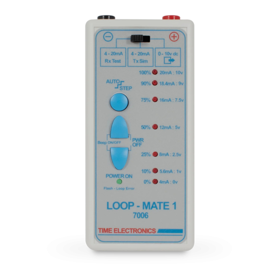
Time Electronics User Manual 7006 Loop-Mate 1 Loop Simulator v1.1 Front panel controls Output Terminals Function Switch Auto Step Button Output LED Indicators Up / Down Control Buttons Power / Error LED 7006 Loop-Mate 1 Loop Simulator Page 7 of 22... -
Page 8: Operation
Time Electronics User Manual 7006 Loop-Mate 1 Loop Simulator v1.1 Operation Function Select The Loop-Mate 1 has 3 functions: 1. Function 1 ....Rx TEST (4-20 mA) 2. Function 2 ....Tx SIM (4-20 mA) 3. Function 3 ....0-10 v dc SIM These are selected using the function select switch. - Page 9 Time Electronics User Manual 7006 Loop-Mate 1 Loop Simulator v1.1 (transmitter): This component converts physical signals such as pressure, temperature, flow, and level etc, into the loop signals (4 - 20 mA or 0 - 10 V). (receiver): This component measures the loop signal and either displays it (indicator) or converts it to another form e.g.
-
Page 10: Rxtest Function 4 - 20 Ma
Time Electronics User Manual 7006 Loop-Mate 1 Loop Simulator v1.1 RxTest function 4 - 20 mA The unit can provide current output from 4-20 mA with an internally generated loop excitation drive capability. There are seven output set-points over the span. They are indicated on the front panel in both ‘percentage of the span’... -
Page 11: Txsim Function 4 - 20 Ma (Current Sink)
Time Electronics User Manual 7006 Loop-Mate 1 Loop Simulator v1.1 TxSim function 4 - 20 mA (Current Sink) Using the TxSim function the unit takes its excitation power from the loop and acts as a current sink. The excitation supply voltage must be in the range 5 to 50 volts DC. -
Page 12: 10Vsim Function 0 - 10V
Time Electronics User Manual 7006 Loop-Mate 1 Loop Simulator v1.1 10vSim function 0 - 10V The unit outputs voltage in the range of 0 to 10 V. There are seven set-points. The selected set-point is indicated on the front panel in both ‘percentage of span’ and actual volts. -
Page 13: Additional Features
Time Electronics User Manual 7006 Loop-Mate 1 Loop Simulator v1.1 Additional Features Auto Step The Loop-Mate 1 has the ability to automatically step through the set-points, both up and down. This feature is available for any of the 3 functions (RxTest, TxSim, 10vSim). -
Page 14: Loop Error Indication
Time Electronics User Manual 7006 Loop-Mate 1 Loop Simulator v1.1 Loop Error Indication Error display on the Loop-Mate1 Loop Error LED With the RxTest function selected If the loop is open circuit or resistance too high, the error LED will start flashing. However, short circuit on the loop is not indicated. -
Page 15: Power Supply
Time Electronics User Manual 7006 Loop-Mate 1 Loop Simulator v1.1 Power supply Battery life The unit is powered by a single PP3 battery. Types that can be used are Zinc Carbon (250 mAh), Alkaline (450 mAh), Lithium (1200 mAh) and rechargeable (150 mAh). For best performance Lithium batteries are recommended. -
Page 16: Maintenance
Calibration equipment required A bench multimeter with accuracy of 0.02 % or better. Examples of suitable instruments are Time Electronics’ 5075 or HP 34401A. Calibration should be done at 20 °C ± 10 °C. 7.1.2 Calibration (RxTest - Current source) 1. - Page 17 Time Electronics User Manual 7006 Loop-Mate 1 Loop Simulator v1.1 7.1.3 Calibration (Voltage) 1. Connect the multimeter to the output terminals of the Loop-Mate 1. 2. Set the function switch to 0 - 10 V DC. 3. Select the most suitable range on the multimeter to measure 10 V DC.
-
Page 18: Adjustment Of Calibration
Time Electronics User Manual 7006 Loop-Mate 1 Loop Simulator v1.1 Adjustment of Calibration When Loop-Mate1 is found to be out of specification the procedures described in the following sections can be followed to adjust and calibrate instrument. 7.2.1 Disassembling Loop-Mate1 1. - Page 19 Time Electronics User Manual 7006 Loop-Mate 1 Loop Simulator v1.1 7.2.2 Trimmer Locations (used for adjusting the calibration) 7.2.3 RxTest (Current source) Adjustment Calibration Connect the multimeter to the output terminals of the Loop-Mate 1. • Set the function switch to RxTest.
- Page 20 Time Electronics User Manual 7006 Loop-Mate 1 Loop Simulator v1.1 7.2.4 10vSim (Voltage) calibration Connect the multimeter to the output terminals of the Loop-Mate1. • • Set the function switch to 0 – 10 V DC Sim. Select the most suitable range on the multimeter to measure 10 V DC.
-
Page 21: Warranty And Servicing
Time Electronics’ total liability is limited to repair or replacement of the product. Note that if Time Electronics determine that the fault on a returned product has been caused by the user, we will contact the customer before proceeding with any repair. - Page 22 Returning Instruments Prior to returning your product please contact Time Electronics. We will issue a return merchandise authorization (RMA) number that is to accompany the goods returning. Further instructions will also be issued prior to shipment. When returning instruments, please ensure that they have been adequately packed, preferably in the original packing supplied.
Need help?
Do you have a question about the 7006 and is the answer not in the manual?
Questions and answers