Table of Contents
Advertisement
Quick Links
User Manual
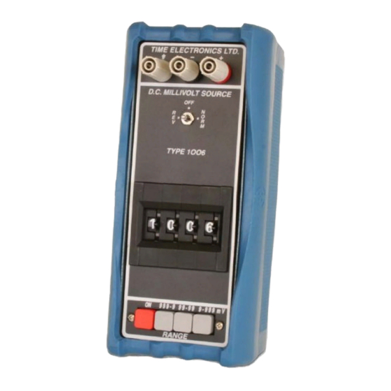
1006 DC Millivolt Source
and
1007 DC Millivolt Potentiometer/Source
Version 1.2
9-22
Time Electronics Ltd
Unit 5, TON Business Park, 2-8 Morley Road,
Tonbridge, Kent, TN9 1RA, United Kingdom.
T: +44 (0) 1732 355993 | F: +44 (0) 1732 350198
mail@timeelectronics.co.uk | www.timeelectronics.com
Advertisement
Table of Contents

Related Manuals for Time Electronics 1006


Summary of Contents for Time Electronics 1006
- Page 1 User Manual 1006 DC Millivolt Source 1007 DC Millivolt Potentiometer/Source Version 1.2 9-22 Time Electronics Ltd Unit 5, TON Business Park, 2-8 Morley Road, Tonbridge, Kent, TN9 1RA, United Kingdom. T: +44 (0) 1732 355993 | F: +44 (0) 1732 350198...
- Page 2 All rights reserved. Nothing from this manual may be multiplied, or made public in any form or manner, either electronically or hard copy, without prior written consent from Time Electronics Ltd. This also applies to any schematics, drawings and diagrams contained herein.
-
Page 3: Table Of Contents
Time Electronics User Manual 1006 / 1007 DC Millivolt Source v1.2 Contents Introduction ............................ 4 1006 DC Millivolt Source ........................4 1007 DC Millivolt Potentiometer and Source ..................5 Specifications ............................6 Controls ............................7 1006 Controls ............................7 1007 Controls ............................8 Operating Instructions ........................ -
Page 4: Introduction
Power is provided by 6 AA batteries. Battery life is several months, depending on usage. The battery condition is monitored by an indicator situated on the top of the unit. The 1006 has up to 20 mA drive current and is short circuit and overload protected. An off/normal/reverse output polarity switch is provided. -
Page 5: 1007 Dc Millivolt Potentiometer And Source
• Description The 1007 includes all the features of the 1006 with the addition of a microvolt null balance display. This enables it to be used for potentiometric voltage measurement in addition to its function as a calibrator. The null zero and sensitivity are adjustable via front panel controls - maximum sensitivity enables null balance to resolve 1 µV. -
Page 6: Specifications
Time Electronics User Manual 1006 / 1007 DC Millivolt Source v1.2 Specifications Output: 0 to 999.9 mV in 3 ranges: 0 to 999.9 mV in 0.1 mV steps 0 to 99.99 mV in 10 μV steps 0 to 9.999 mV in 1 μV steps Accuracy: ±... -
Page 7: Controls
Time Electronics User Manual 1006 / 1007 DC Millivolt Source v1.2 Controls 1006 Controls Output Terminals Case Terminal Output Polarity Switch Set output polarity. Centre position provides a short circuit on the 1006 output terminals. Output Voltage Setting Selected on a 4-digit thumbwheel switch. -
Page 8: 1007 Controls
1006 / 1007 DC Millivolt Source v1.2 1007 Controls The 1007 incorporates a 1006 with the addition of a microvolt null detector and enables the unit to be used for potentiometric measurements. The additional components are highlighted with green boxes below. -
Page 9: Operating Instructions
POLARITY SWITCH NOTE: On the 1006, the “off” polarity position disconnects the output & provides a short circuit on the output terminals. On the 1007, the “off” polarity position provides an open circuit on the output terminals. This is to prevent accidental shorting of the voltage under test when the unit is being used as a potentiometer. -
Page 10: 1007 Mv Potentiometric Null Operation
Time Electronics User Manual 1006 / 1007 DC Millivolt Source v1.2 1007 mV Potentiometric Null Operation Due to the extreme sensitivity of the electronic null detector (3 µV/div.) it is important to ensure that it is correctly zeroed before attempting accurate measurements. -
Page 11: Servicing And Calibration
The range of adjustment of the trimmers is given below. Access to the 1006 or 1007 is by removing the blue case cover which is located by 8 screws. 1006 DC mV Source The 1006 contains 4 (3 on instruments with serial number earlier than 1320) internal preset trimmers. - Page 12 1006 output within specification. The maximum amount of adjustment available on this trimmer is 0.8 %. 6) Select 99.99 mV range on the 1006 and set the voltage source to 99.99 mV. Adjust the ‘100mV CAL’ trimmer to bring the output within specification. The maximum amount of adjustment available on this trimmer is 0.8 %.
- Page 13 1007 Millivolt Source and Potentiometer The 1007 incorporates a 1006 with the addition of a microvolt null detector. With the front panel function switch in the ‘SOURCE’ position, the unit operates as a 1006 and the ZERO and CALIBRATION setting procedures are identical to those for the 1006.
-
Page 14: Warranty And Servicing
Time Electronics’ total liability is limited to repair or replacement of the product. Note that if Time Electronics determine that the fault on a returned product has been caused by the user, we will contact the customer before proceeding with any repair. - Page 15 Returning Instruments Prior to returning your product please contact Time Electronics. We will issue a return merchandise authorization (RMA) number that is to accompany the goods returning. Further instructions will also be issued prior to shipment. When returning instruments, please ensure that they have been adequately packed, preferably in the original packing supplied.
Need help?
Do you have a question about the 1006 and is the answer not in the manual?
Questions and answers