Table of Contents
Advertisement
Quick Links
Advertisement
Table of Contents

Related Manuals for Prusa Research i3 MK2.5


Summary of Contents for Prusa Research i3 MK2.5
- Page 2 Important notice, tip, hint or information that helps you print with ease. Read carefully! This part of the text has the greatest importance - either for user safety or for p roper p rinter service. Handbook version 2.50 from March 2, 2018 © Prusa Research s.r.o.
- Page 3 About the author rd Josef Prusa (born Feb 23 , 1990) became interested in the 3D printing phenomenon before joining Prague’s University of Economics in 2009 - at first it was a hobby, a new technology open to changes and improvements. The hobby soon became a passion and Josef grew into one of the leading developers of Adrien Bowyer’s international, open source, RepRap project.
-
Page 4: Table Of Contents
Table of contents 2 Product details 3 Introduction - G lossary , D isclaimer , S afety instructions 4 Licenses 5 Original Prusa i3 MK2.5 printer upgrade 6 First steps 6.1 Preparing for the upgrade 6.2 Setup before printing 6.2.1 Calibration flow and wizard... - Page 5 8 Advanced Calibration 8.1 PID tuning for Hotend (Optional) 8.2 PINDA probe calibration/ Temp. calibration (Experimental/Optional) 8.3 View XYZ calibration details (Optional) 8.4 Linear Advance (Experimental) 8.5 Extruder info 9 Printer drivers 10 Printing your own models 10.1 Where can you get the 3D models? 10.2 In what program can you create your own models? 10.3 PrusaControl 10.4 Slic3r Prusa Edition...
-
Page 6: Product Details
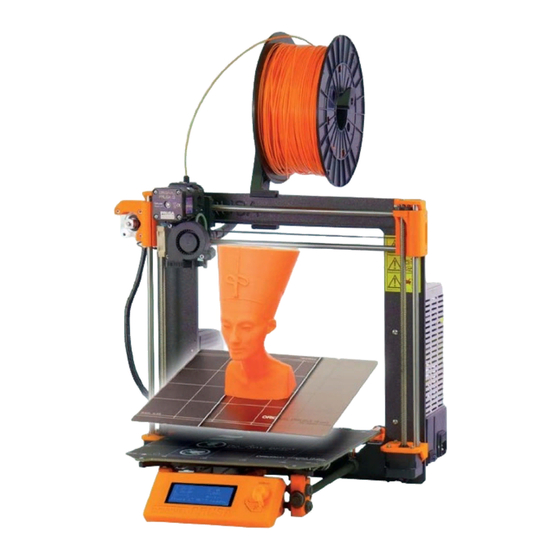
O riginal Prusa i3 MK2.5 i s a upgrade of Original Prusa i3 MK2S with numerous hardware and software improvements, which lead to improved reliability as well as ease of use and assembly. -
Page 7: Licenses
4 Licenses The Original Prusa i3 MK2.5 p rinter is a part of the RepRap project, the first open source 3D printer project free to use under a G NU G PL v3 l icense (... -
Page 8: Original Prusa I3 Mk2.5 Printer Upgrade
5 Original Prusa i3 MK2.5 printer upgrade Original Prusa i3 MK2.5 upgrade is shown in p i ct . 1. This upgrade for the Original Prusa MK2S gives you the best features of the Original Prusa MK3 including the magnetic bed with removable spring steel sheet, whole new extruder head, Noctua fan, filament sensor and more. - Page 9 Pict. 1 - Original Prusa i3 MK2.5 printer upgrade Pict. 2 - Description of Original Prusa i3 MK2.5 ...
-
Page 10: First Steps
6 First steps 6.1 Preparing for the upgrade For the assembling Original Prusa i3 MK2.5 u pgrade for the Original Prusa i3 MK2/S , we suggest following the guidelines and assembling the kit according to the o nline manual at manual.prusa3d.com... -
Page 11: Calibration Flow And Wizard
6.2.1 Calibration flow and wizard With your first start-up of your freshly-assembled printer, it will guide you through all the tests and calibrations you need to do to get started printing. Wizard can be also started manually from L CD menu - C alibration - Wizard . Do not forget to read chapter 6 .2.2 Flexible steel sheet surface preparation... -
Page 12: Flexible Steel Sheet Surface Preparation
There are few special occasions where you will need to redo the calibration or a part of it. ● Firmware update - A complete guide is in the chapter 1 2.9 Updating printer firmware . After major firmware releases, we suggest to go through the calibration process using the Wizard. - Page 13 Pict.5 - Steel print sheets - smooth PEI sheet, glossy powder-coated PEI and textured powder-coated PEI All original print surfaces from Prusa Research are coated from both sides. Pict. 6 - Smooth PEI sheet (top) vs textured powder coated PEI (bottom) effect on first layer...
-
Page 14: Double-Sided Textured Pei Powder-Coated Spring Steel Sheet
6.2.2.1 Double-sided textured PEI powder-coated spring steel sheet Powder coating directly on metal makes it very hard to damage this build plate. If a heated nozzle crashed into it, the metal can dissipate the heat. Powder coating also gives the surface a distinct textured look that will be visible on your prints. -
Page 15: Increasing The Adhesion
6.2.3 Increasing the adhesion In some special occasions, such as a tall object with a very small contact area with the print surface, you might need to increase the adhesion. Fortunately, PEI is a very chemically resistant polymer and you can temporarily apply other adhesion solutions without damaging it. -
Page 16: Selftest Error Messages And Resolution
6.2.5 Calibrate XYZ The Original Prusa i3 MK2.5 comes with a full mesh bed leveling feature, however, for this to work, we need to first calibrate the distance between the tip of the nozzle and the PINDA ( P r usa I ND u ction A u toleveling) probe. The process is fairly straightforward; so let’s get to it. -
Page 17: Calibrate Xyz Error Messages And Resolution
run the X YZ calibration f rom the C alibration m enu on the LCD panel. This should not be necessary on the assembled printers as those are factory calibrated. Place a sheet of a regular office paper (for example, the checklist shipped with every order) and hold it under the nozzle during the first round (first 4 points being checked) of calibration. - Page 18 1) XYZ calibration failed. Bed calibration point was not found. The calibration routine did not find a bed sensor point. The printer stops close to the bed point, which it failed to detect. Please verify, that the printer is assembled correctly, that all axes move freely, the pulleys do not slip and the print nozzle is clean.
-
Page 19: Y Axis Alignment
At the end of the X/Y calibration, the printer measures the reference height above each of the 9 bed sensor points and stores the reference heights in nonvolatile memory. During normal bed leveling, it is expected that the PINDA probe triggers no more than 1 mm from the reference value, therefore the nozzle is not allowed to move more than 1 mm below the reference value during the bed calibration. -
Page 20: Calibrate Z
make a 1 mm adjustment to both the front and the back. Loosen the Y belt holder screws, push the belt holder part towards the Y motor and retighten the screws. 6.2.6 Calibrate Z Calibrate Z is located in the L CD Menu - Calibration - Calibrate Z . I t is always done with the steel sheet on.... -
Page 21: Loading The Filament Into The Extruder
Pict. 8 - Visualisation of mesh bed leveling 6.2.8 Loading the filament into the extruder Before you can load the filament, you have to preheat the printer for the correct filament type. 1. Press the control knob to enter the main menu on the LCD. 2. -
Page 22: Unloading The Filament
Pict. 9 - Loading the filament into the extruder Always check if the filament is flowing from the nozzle! If you change the filament for a different one, do not forget to completely remove the old filament before printing by extruding the filament from L CD Menu - Settings - Move axis - Extruder ... -
Page 23: First Layer Calibration
6.2.9 First layer calibration Now we will finally calibrate the distance between the tip of the nozzle and the probe. Check if your print surface is clean! Y ou can find instructions on how to clean it in the chapter 6 .2.2 Flexible steel sheet surface preparation... -
Page 24: Bed Level Correction
Loosen the M3 screw on the probe holder to make adjustments. Gently push or pull the sensor to adjust the height and tighten the M3 screw again. T hen re-run Calibrate Z followed by the First layer calibration again. Pict. -
Page 25: Check Probe Height
Pict. 12 - Perfect Prusa logo first layer 6.2.10.2 Check probe height If the first layer seems inconsistent between multiple prints, the probe might be too high. Lower it slightly. Loosen the M3 screw on the probe holder and gently push the sensor to adjust the height and tighten the M3 screw again.. -
Page 26: Printing
7 Printing Make sure that the n ozzle and the bed are heated to the desired temperature. If you forget to preheat the p rinting n ozzle and the bed before p rinting, the p rinter will automatically check the temperatures of the ... -
Page 27: Printer Control
2. Heatbed temperature (actual / desired temperature) 3. Progress of p rinting in % - shown only during the p rinting 4. Status bar (Prusa i3 MK2.5 ready / H eating / file_name.gcode, etc.) 5. Z-axis position 6. -
Page 28: Controlling The Lcd Screen
7.2.2 Controlling the LCD screen Controlling the LCD screen is done by a single control element: a rotational knob that you press to confirm. Pict. 16 - LCD screen and control buttons By single pressing the control button on the information screen, you enter the main menu. The reset button is placed directly under the control knob. -
Page 29: Fail Stats
(shifted layers) or if you’re manually adjusting speed of printing to more than 100%, use Hi-power mode. Original Prusa i3 MK2.5 also offers the A uto Power Mode . It s ets stepper motors power which lies between silent and high power mode. In Auto Power Mode stepper currents depend on Z height. -
Page 30: Sd Card Sorting
If you experience random glitches after a firmware update, or after a printer upgrade, use the All data option. 7.2.7 SD card sorting The list of the files on the SD card can be sorted; you can change the sorting type in L CD - Settings - Sort:... -
Page 31: Lcd Layout
7.2.9 LCD layout Items not mentioned below are not used for the common p rint setup - you should not change any of the unmentioned i tems unless you are absolutely sure what you are doing. ❏ Info screen ❏... - Page 32 ❏ SD card - Normal / FlashAir ❏ Sort - Time / Alphabet / None ❏ Calibration Wizard ❏ First layer calibration ❏ Auto home ❏ Selftest ❏ Calibrate XYZ ❏ Calibrate Z ❏ Mesh Bed Leveling ❏ Bed level correction ❏...
-
Page 33: Print Speed Versus Print Quality
LCD-knob counterclockwise. Minimum usable printing speed is around 20 % of the nominal speed. 7.2.11 USB cable and Pronterface We strongly recommend using the LCD panel while printing on the Prusa i3 MK2.5 - Pronterface doesn’t support all functions of the new firmware (e.g. filament change while printing). - Page 34 Keep in mind that when printing from Pronterface, the c omputer must be connected to the printer during the whole p rinting process - the computer must be prevented from sleep, hibernation, or shutting down. Disconnecting the computer during the p rint ends the p rinting without the option to finish the object.
-
Page 35: Temperatures
Pict. 22 - Pronterface 1. Load file button is used to l oad the desired m odel . The m odel must be in a * . gcode file format. 2. Choose the port by which the p rinter is connected to the computer (mostly /usbmodem ... -
Page 36: Printer Addons
1 2.6 Replacing / changing the nozzle. 7.3.1.1 Hardened steel nozzle by E3D E3D, a UK-based company, that supplies hotends for the Original Prusa i3 MK2.5, has a whole ecosystem of upgrades and addons. We support some of them including the hardened steel nozzle. -
Page 37: Advanced Calibration
8 Advanced Calibration Additional calibration tools and settings for advanced users are available, but they are entirely optional and some of them are even experimental. 8.1 PID tuning for Hotend (Optional) If you are experiencing wide swings in temperatures of your nozzle (e.g +/- 5 C °), ... -
Page 38: View Xyz Calibration Details (Optional)
Do not touch the nozzle or heatbed during this process until the process is fully finished as it will reach high temperatures! Once calibrated, your PINDA probe will be comparing its data readings under different temperatures and also, additionally, it will include your Live Z data. This should help you to have a stable Live Z. - Page 39 If you are using different slicers from Slic3r PE or PrusaControl, or you just want to tweak and play around with different values, you can manually change the settings in gcode script. H owever, i f you do not understand the concept of gcodes yet, or never played with editing it, stop reading here and skip to another chapter.
-
Page 40: Extruder Info
8.5 Extruder info Extruder info provides debug information about the extruder sensors. It provides info of: ● Extruder cooling fan RPM ● Information of filament moving in the extruder ● Illumination level of the filament sensor - optimally below 100 This information can be used to check the function of the fans and assess how well particular filament works with the sensor. -
Page 41: Printer Drivers
9 Printer drivers Latest drivers and information can be found at w ww.prusa3d.com/drivers The driver package contains the following settings and programs: PrusaControl - converting the 3D models to .gcode format for printing. Slic3r Prusa Edition - converting the 3D models to .gcode format for printing. Pronterface ... -
Page 42: Prusacontrol
provides a quick guide a long with d etailed video tutorials so it is an ideal choice for novice enthusiasts. There is a great deal of 3D programs - free or paid - your choice depends more on your personal taste and preferences. - Page 43 Pict. 26 - Prusa Control interface 1. Undo/Redo buttons return changes. 2. Scale button allows you to scale with the mouse while the model is selected. 3. Rotate button allows you to rotate with the mouse while the model is selected (outer circle step are 0,1°, inner circle step is 45°.) 4.
-
Page 44: Slic3R Prusa Edition
10.4 Slic3r Prusa Edition PrusaControl is built on top of the S lic3r Prusa Edition and hides all the unnecessary clutter you would have if all the settings were exposed. If you choose to create your own specific print settings, or tweak the material settings heavily, you can use Slic3r PE directly. Pict. -
Page 45: Bundled 3D Models
10.5 Bundled 3D models We asked a couple of known 3D designers to prepare some printable objects for you to print. They are ideal for the first prints on your new printer. STL and GCODE files are available after installing the drivers package in the “3D Objects” folder, or bundled on your SD card. You can check them out at ... - Page 46 Pict. 30 - Adding color change in PrusaControl ● First of all, you need to prepare regular g code with common print and filament settings. Save the file. ● Then go to w ww.prusaprinters.org and choose C olor Print in the header menu. ●...
- Page 47 Pict. 31 - Web version of Colorprint interface at prusaprinters.org/colorprint Insert the filament which you want to start with into your printer and start printing the file. When the color change is triggered from the gcode, the printer will follow this simple procedure: ●...
-
Page 48: Printing Of Non-Standard Models
Other option for m ulticolored p rint i s to u se the f ilament change option. Choose the T une a nd then C hange f ilament option during the p rint . The printer will pause the ... -
Page 49: Large Object Printing
10.7.2 Large object printing Another special p rinting case is when p rinting objects larger than the h eatbed . The first option is to resize the object to a printable s ize . Right-click on an object in Slic3r opens a menu with the ... -
Page 50: Materials
11 Materials Temperatures and the heatbed treatment before a print according to a specific material. 11.1 ABS ABS is a very strong and versatile material with g reat thermal resistance . It’s suitable for both indoor and outdoor use. ABS is a thermoplastic polymer; that means that just like PLA, it can be melted and crystallized multiple times without degrading too much. - Page 51 11.2 PLA PLA is the most commonly used filament. It’s b iodegradable , e asy to print , and a very strong m aterial. The perfect choice for printing l arge o bjects thanks to its low thermal expansion (little to no warping) and for printing ...
- Page 52 11.3 PET/PETG PETG is a very tough material with good thermal resistance. Its use is universal but especially suitable for mechanical parts and both indoor and outdoor use. PETG has almost no warping , so printing large objects isn’t a problem. We use PETG to print parts for our printers! PETG is one of our favorite materials for 3D printing.
- Page 53 11.4 HIPS HIPS is high impact polystyrene, and as for behavior, it's similar to ABS, so it's easy to print. It's a universal and stable material with excellent heat resistance, and it produces very smooth layers. HIPS is also very malleable, and it can be dissolved using limonene. HIPS is mostly suited for printable mechanical components.
- Page 54 11.6 Nylon (Taulman Bridge) Nylon is a very tough material suitable for mechanical parts. ADVANTAGES DISADVANTAGES Durable Demanding storage (it’s hygroscopic) Chemically resistant Flexible, but strong Chemical resistance ● Nozzle temperature: 2 40 °C ● Bed temperature: 8 0 - 9 0 °C. ●...
- Page 55 ● Heatbed: M ake sure the surface is clean as described in 6 .2.2 Flexible steel sheet surface preparation chapter. Some very soft flex materials can bond to the bed too much and require use of glue on the bed as a separator to prevent PEI damage. 11.8 Composite materials ...
- Page 56 ● Nozzle temperature: 2 70 - 280 °C ● Bed temperature: 1 00 - 110 °C (bigger object -> higher temp.) ● Heatbed: M ake sure the surface of the heatbed is clean. Usage of brim is suggested (see Prusa Knowledgebase).
-
Page 57: Dialing In New Materials
11.12 Dialing in new materials Even though each manufacturer produces slightly different material, they belong to a same group. For example, Prusa PLA and ColorFabb PLA will have a slightly different output when printed. To achieve the best possible output, you should experiment with the n ozzle temperature , fan speed... -
Page 58: Faq - Printer Maintenance And Print Issues
12 FAQ - Printer maintenance and print issues 12.1 Regular maintenance 12.1.1 Bearings Every couple hundred hours, the smooth rods should be cleaned with a paper towel. Then apply a little bit of general purpose machine oil on the smooth rods and move the axis back and forth a couple of times. -
Page 59: Extruder Drive Gear
The nozzle cooling fan is made by N octua . These premium fans are known for their superb quietness and exceptional performance. You can turn off the monitoring of Noctua fan in L CD menu - S ettings - Check fans . 12.1.3 Extruder drive gear ... -
Page 60: Running Out Of Filament
12.3.1 Running out of filament Running out of filament w ill no longer cause a print failure . If you run out of filament, the printer will automatically pause the print, unload the remaining few centimeters in the heatbreak, and move the X-carriage away from the print. You will be prompted to replace the spool and insert a new filament. -
Page 61: Clogged / Jammed Extruder
If everything is in order, other causes might be: 12.3.3.1 Dust on the sensor - how to clean If you start getting a lot of false alarms on filament jams or filament running out, your sensor might need cleaning. The easiest way is to use a compressed air. There is a dedicated hole in the x-carriage exactly for this purpose. -
Page 62: Nozzle Cleaning
Pict. 39 - C leaning the extruder - you can see the hobbed pulley through the service hole 12.5 Nozzle cleaning Do not touch the nozzle during these procedures as it is preheated and you may burn yourself! To make cleaning easier, move the extruder head up. -
Page 63: Replacing / Changing The Nozzle
3. Push the a cupuncture needle i nto the nozzle again and repeat these steps a few times more. When the filament is extruded properly, the nozzle is clear. None of the filament is going through the nozzle If none of the filament is going through, then most likely, your hotend got clogged. - Page 64 Pict. 40 - N ozzle change ...
-
Page 65: Printing Problems
12.7 Printing problems 12.7.1 Layers break and split when printing from ABS material ABS m aterial has a higher thermal expansion than other m aterials . We suggest other materials like PET, HIPS or PLA when you p rint larger m odels . 12.7.2 Models contain either too much or not enough of the filament ... -
Page 66: Faq - Common Issues When Assembling The Printer Kit
13 FAQ - common issues when assembling the printer kit 13.1 Nozzle/print surface gap is greater in the middle than at the corners The reason of this issue isn’t the bent printer surface or bed but a distorted Y-axis. We suggest to remove the whole Y-axis out of the printer. -
Page 67: Printer Stops Printing Soon After Start
13.2 Printer stops printing soon after start Extruder is likely to be overheated. Make sure the n ozzle fan is working p roperly . If not, please inspect its connection according to the assembly manual. Pict. 42 - P roper wiring of the connectors 13.3 Printer can’t read the SD card ... -
Page 68: Loose X- And/Or Y-Axis Belts
13.4 Loose X- and/or Y-axis belts Check if both belts are properly tightened, loose belts would cause a printer malfunction and prevent proper printing. The easiest way to check is printing a round object - if any of the belts are not tightened properly the result is an irregular shape instead of a perfect circle. Y-axis belt is located under the heatbed, X-axis belt moves the extruder. -
Page 69: Detached Cables To The Heatbed
13.5 Detached cables to the heatbed Do not forget to use a spiral wrap on h eatbed c ables and attach the c ables p roperly so they won’t restrict movement during printing. Pict. 45 - C ables should be wrapped in a spiral wrap... - Page 70 Print and share! Do not forget to tag your prints with #prusai3mk3 while sharing so we can find, pin and showcase them with our http://www.prusa3d.com/original-prusa-i3-prints/ Happy Printing :) ...
Need help?
Do you have a question about the i3 MK2.5 and is the answer not in the manual?
Questions and answers