Table of Contents
Advertisement
Quick Links
Advertisement
Table of Contents

Related Manuals for Prusa Research Original Prusa i3 MK2


Summary of Contents for Prusa Research Original Prusa i3 MK2
- Page 2 Please always refer to the ttp://www.prusa3d.com/drivers/ for an updated version of this 3D printing handbook (PDF download). QUICK GUIDE TO THE FIRST PRINT 1. Read the safety instructions carefully ( p age 7 ) 2. Place the printer on a flat and stable surface ( p age 11 ) 3. Download and install the drivers ( p age 31 ) 4. Calibrate the printer by following our calibration flow ( p age 11...
-
Page 3: About The Author
About the author Josef Prusa (born Feb 23 , 1990) became interested in the 3D printing phenomenon before joining the Prague’s University of Economics in 2009 at first it was a hobby, a new technology open to changes and improvements. The hobby soon became a passion and Josef grew into one of the leading developers of Adrien Bowyer’s international, open source, RepRap project. Today, you can see the Prusa design in different versions all around the world, it is one of the most popular printers and thanks to it, knowledge about the 3D printing technology significantly increased among public. Jo’s work on selfreplicating printers (you can print the other printer parts with your printer) are still ongoing and currently there is Prusa i3 the third iteration of the original 3D printer. It is constantly updated with the latest innovations and you've just purchased its latest version. In addition to printer hardware upgrades, the main goal is to make the technology more accessible and understandable for all users. Josef Prusa also organizes workshops for the public, participates in professional conferences dedicated to the popularization of 3D printing. For example, he lectured at the TEDx conference in Prague and Vienna, at World Maker Faire in New York, Maker Faire in Rome or at the Open Hardware Summit hosted by MIT. Josef also teaches Arduino at Charles University and was also a lecturer at the Academy of Arts in Prague. In his own words, he imagines 3D printers will be available in every home in a not too distant future. If anything is needed, you can simply print it. In this field, you just push the boundaries every day... We're glad you're part of it with us! ... -
Page 4: Table Of Contents
Table of contents About the author 3 2 Product details 6 3 Introduction 6 3.1 Glossary 6 3.2 Disclaimer 7 3.3 Safety instructions 7 3.4 Licenses 7 4 Original Prusa i3 MK2 printer 8 5 Original Prusa i3 MK2 printer kit 9 6 First steps 10 6.1 Printer unpacking and proper handling 10 6.2 Printer assembly 11 6.3 Setup before printing 11 6.3.1 Calibration flow 11 6.3.2 PEI print surface preparation 12 6.3.3 Increasing the adhesion 13 6.3.4 Selftest (kit only) 13 6.3.4.1 Selftest error messages and resolution (kit only) 14 ... - Page 5 7.3.1.1 Hardened steel nozzle 31 7.3.1.2 0.25mm nozzle 31 8 Printer drivers 31 9 Printing your own models 31 9.1 Where you can get the 3D models? 31 9.2 In what program you can create your own models? 32 9.3 Slic3r 32 9.4 Bundled 3D models 33 9.5 Print in color with ColorPrint 34 9.6 Printing of nonstandard models 36 9.6.1 Printing with support material 36 9.6.2 Large object printing 37 10 Materials 38 10.1 ABS 38 10.2 PLA 38 10.3 PET 38 10.4 HIPS 38 10.5 PP 38 10.6 Nylon (Taulman Bridge) 38 10.7 Flex 39 ...
-
Page 6: Product Details
2 Product details Title: Original Prusa i3 MK2 / Original Prusa i3 MK2 (kit), Filament: 1.75 mm Manufacturer: Prusa Research s.r.o., 621/8a Prvniho pluku, Prague, 186 00, Czech Republic Contacts: phone +420 222 263 718, email: nfo@prusa3d.com EEE group: 3 (IT and/or telecommunication equipment), Device use: indoor only Power supply: 90135 VAC, 2 A / 180264 VAC, 1 A (5060 Hz) Working temperature range: 18 °C (PLA)38 °C, indoor use only Working humidity: 85 % or less Kit weight (brutto / netto): 9.8 kg / 6.3 kg, assembled printer weight (brutto / netto): 12 kg / 6.3 kg. Serial number is located on the printer control unit and also on the packaging. 3 Introduction Thank you for purchasing our original 3D p rinter O riginal Prusa i3 MK2 f rom Josef Prusa either as an assembled p rinter or a p rinter kit as your purchase supports us with its further development. Read the handbook carefully, please, all chapters contain valuable info for the correct service of the p rinter . ... -
Page 7: Disclaimer
3.2 Disclaimer Failure to read the Manual may lead to personal injury, inferior results or damage to the 3D printer. Always ensure that anyone who operates the 3D printer knows and understands the contents of the Manual. We can not control the conditions in which you assemble the Original Prusa i3. For this and other reasons we do not assume responsibility and expressly disclaim liability for loss, injuries, damage, or expense arising out of or in any way connected with the assembly, handling, storage, use or disposal of the product. The information in this Manual is provided without any warranty, express or implied, regarding its correctness. 3.3 Safety instructions Please be very cautious during any interaction with the p rinter . This printer is an electrical device with moving parts and hottemperature areas. 1. Device is for indoor use only. Do not expose the printer to rain or snow. Always keep the printer in a dry environment at a minimum distance of 30 cm from other objects. 2. Always place the printer on a stable place, where it can not fall or tip over. 3. The printer supply is household power outlet 230 VAC, 50 Hz or 110 VAC / 60 Hz; Never connect the printer to a different power supply, it may cause malfunction or damage to the printer. 4. Place the power cord so you can’t stumble on it, or step on it or otherwise expose to any damage. Make sure that the power cord is not mechanically or otherwise damaged. Stop using damaged cable immediately and replace it. 5. When you disconnect the power cord from the socket, pull the plug rather than the cord to reduce the risk of damage to plug or AC outlet. 6. Never disassemble the printer power supply, it does not contain any parts that could be repaired by an unskilled worker. All repairs must be provided by a qualified technician. 7. Do not touch the nozzle or heat bed when the printer is printing or is warming up. Note that the temperature of the nozzle is 210300 °C (410572 °F); heatbed temperature can reach over 100 °C (212 °F). Temperatures above 40 °C (104 °F) can cause harm to human body. 8. Do not reach inside the printer while it is still in operation. An injury may be caused by its ... -
Page 8: Original Prusa I3 Mk2 Printer
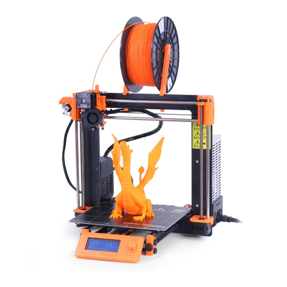
4 Original Prusa i3 MK2 printer Unlike the p rinter kit, it’s completely assembled and almost ready to p rint . After plugging in and running the necessary calibration you, can p rint a 3D object in the matter of minutes after unpacking the p rinter . Keep in mind you can use our s upport email when you purchased the assembled p rinter . Do not hesitate to write us if you need any advice or help. We will gladly help with any specific prints. 3D printers use two different diameters of a f ilament (you can find more in chapter ... -
Page 9: Original Prusa I3 Mk2 Printer Kit
5 Original Prusa i3 MK2 printer kit Original Prusa i3 MK2 kit is pictured in p i ct . 2. D etailed information and assembly description can be found in chapter 6 .2 Printer assembly . We offer the s upport for users who purchased the p rinter kit through our official forum. If you need help do not hesitate to visit our forum at f orum.prusa3d.com . You can find the answers for your problem there. If not, please just post your question directly there. ... -
Page 10: First Steps
6 First steps 6.1 Printer unpacking and proper handling Holding the upper frame, take the printer and pull it out from the box. Be careful when handling the p rinter not to damage the electronics and thus the p roper p rinter functionality. Anytime you move the p rinter, always hold the upper frame with hotbed upright pointing away from you as pictured in p i ct . 3A . Do not forget to remove all shipping helpers parts shown in pic 3B or the white zipties used. ... -
Page 11: Printer Assembly
6.2 Printer assembly With Original Prusa i3 MK2 p rinter kit we suggest to follow the guidelines and assemble the kit according to the the o nline manual at m anual.prusa3d.com . ( O nline manual is available in several languages on the website). The construction of the printer should not take more than one working day. After a successful completion continue to the chapter 6 .3 Setup before printing . 6.3 Setup before printing ● Place the p rinter to a horizontally stable position, best place is a workbench where there is no risk of ... -
Page 12: Pei Print Surface Preparation
6.3.2 PEI print surface preparation To achieve the best adhesion on the new surface, it is important to keep the surface clean. Cleaning of the surface is very easy. The best option is I sopropyl alcohol a vailable in drugstores which is the best for ABS, PLA and others, except for PETG where the adhesion may be too strong. Second option is to use a gentle spray of a w indow cleaner (Windex or similar) on a paper towel and wipe the surface. The bed can be cleaned even while hot, just be careful not to touch the surface or the nozzle. Alternatively, you can clean the bed with warm water and a few drops of a dish soap on a paper towel. D enatured alcohol is yet another option. The surface does not have to be cleaned before every print! It is just important to n ot touch the print bed with y our hands or d irty tools . C lean your tools with the same solution... -
Page 13: Increasing The Adhesion
6.3.3 Increasing the adhesion In some special occasions, like a tall object with a very small contact area with the print surface, you might need to increase the adhesion. Fortunately PEI is a very chemically resistant polymer and you can temporary apply other adhesion solutions without damaging it. This also applies to materials which would not stick to PEI otherwise, like Nylon etc. Before applying anything to the bed, consider using B rim option in Slic3r which increases the surface area of the first layer. For PLA and Nylon blends a simple glue stick does the trick. Glue can be later easily removed by window cleaner or dish soap water. For ABS prints, ABS juice can be used and later cleaned with pure acetone. Be very gentle when applying the juice and do so while the bed is cold. Prints will attach very strongly. Prepared j uice can be also purchased in our eshop. Unfortunately, UPS service does not allow to deliver any acetonebased products due to shipping constraints. In that case you get only the bottle and ABS from our eshop and you have to source the acetone locally. 6.3.4 Selftest ( kit only) ... -
Page 14: Selftest Error Messages And Resolution (Kit Only)
6.3.4.1 Selftest error messages and resolution (kit only) Heater/Thermistor Not connected: Check proper wiring of hot end power cables and thermistor cables. Ensure that both are properly connected to the Rambo electronics, and that they are not swapped. Bed/Heater Wiring error: Check that heatbed and hotend power cables are not swapped or thermistor cables from both hotend and heatbed are not swapped in the Rambo electronics. Endstops Wiring error {XYZ}: Check the proper cabling of endstops. Routine indicates axis on which endstop reported malfunction or is not properly responding. Check the proper connection in the Rambo electronics. Motor {XYZ} Endstop {XYZ}: Check that motor and endstop on indicated axis are properly connected to the Rambo electronics and not swapped with motor or endstop of different axis. Axis causing the problems is indicated on the LCD panel. Endstop not hit Motor {XZY}: Check mechanical settings that endstop can be reached when axis is in minimal position. 6.3.5 Calibrate XYZ ( kit only) The Original Prusa i3 MK2 comes with a full mesh bed leveling feature, however for this to work we need to first calibrate the distance between tip of the nozzle ... -
Page 15: Calibrate Xyz Error Messages And Resolution (Kit Only)
The progress and results of each step are displayed on the LCD. In case of errors found, the XYZ calibration is interrupted and the reason for error is shown to guide in troubleshooting. At the start of the XYZ calibration procedure the printer prompts you by a following message: "Calibrating X/Y. Move Z carriage up to the end stoppers. Click when done.” After that, the printer asks you to confirm this step: " Are left and right Z carriages all up?" Please make sure you really move the Z carriage up to the end stoppers until you hear a rattling sound as the Z stepper motors skip steps. This procedure ensures, that 1) the X axis is perfectly horizontal, 2) the print nozzle is in a known distance from the print bed. In case the Z carriage did n ot t ouch the end stoppers, the printer could not possibly know the height of the print nozzle above the print bed and it could therefore crash into the print bed during the first round of the X/Y calibration procedure. The XYZ calibration procedure also prompts you to " Please clean the nozzle for calibration. Click when done." If this advice is not followed and there is a plastic debris on the print nozzle, then the debris may touch the print bed or even push the print bed away from the PINDA probe, so the PINDA probe will not trigger properly and the calibration will fail. Place a sheet of a regular office paper (for example the checklist shipped with every order) and hold it under the nozzle during the first round (first 4 points being checked) of calibration. If the nozzle catches on the paper during the process, power off the printer and lower the P.I.N.D.A. probe slightly. See the P.I.N.D.A. probe response diagram in 6.3.10.2 Check probe height . The paper will not affect the calibration process. The nozzle must not touch the print surface or deflect the bed by any means. If everything went correctly, tighten the bottom nut of the ... - Page 16 of paper and the nozzle is clean, you need to screw the PINDA probe slightly lower and rerun the X/Y calibration. 2) XYZ calibration failed. Please consult the manual. The calibration points were found in positions far from what should be expected for a properly assembled printer. Please follow the instructions of case 1). 3) XYZ calibration ok. X/Y axes are perpendicular. Congratulations, you built your printer precisely, your X/Y axes are perpendicular. 4) XYZ calibration all right. X/Y axes are slightly skewed. Good job, the X/Y axes are not precisely perpendicular, but still quite all right. The firmware will correct for the X/Y skew during normal printing, so boxes will be printed with right angles. 5) X/Y skewed severely. Skew will be corrected automatically. You may consider to realign the X/Y axes (as described in the chapter 6 .3.5.1 Y axis alignment ) . Still the firmware will correct the skew during normal printing and as long as the X and Y axes move freely, the printer will print correctly. 6) XYZ calibration failed. Left front calibration point not reachable. Even if the printer moves the print bed to the end Y end stop, the PINDA probe ...
- Page 17 9) XYZ calibration compromised. Left front calibration point not reachable. XYZ calibration compromised. Right front calibration point not reachable. XYZ calibration compromised. Front calibration points not reachable. Printer will likely work, but the bed leveling may be compromised and the skew of the X/Y axes may not be fully corrected. It is recommended to adjust the positions of the Y threaded rods in the Z frame as in cases 6) to 8). Y ou can find out how to fix this in the next chapter 6 .3.5.1 Y axis alignment . During the mesh bed leveling procedure following errors may be reported on the display. 1) Bed leveling failed. Sensor disconnected or cable broken. Waiting for reset. Verify, whether the PINDA probe cable is plugged into the RAMBo board correctly. If it is the case, the PINDA probe is broken and it needs to be replaced. 2) Bed leveling failed. Sensor didn’t trigger. Debris on nozzle? Waiting for reset. ...
-
Page 18: Y Axis Alignment (Kit Only)
6.3.5.1 Y axis alignment (kit only) For autocalibration to work properly, it is extremely important for the Y axis to be perpendicular to the X axis. This can be easily checked by looking at the printer from the top and visually aligning the Xaxis rods with lines on the heatbed. If the Y axis is misaligned, you can easily adjust the position of the Y axis inside the frame by loosening the M 10 nuts on the Y axis and securing them at the newly adjusted position. You can see how in the A ssembly Manual 7.PSU/Step 18 or in P.I.N.D.A. Probe Misaligned topic at h elp.prusa3d.com . Pic. 5 Xaxis rods must be visually aligned with lines on the heatbed. If the Calibrate XYZ gives “ X YZ calibration compromised. Front calibration points not reachable.” error, you don’t necessarily need to adjust the M10 nuts and position of the axis in the frame, but you can adjust the belt holder position. New version of the Ybeltholder with a slot (shipped from August 8, 2016) allows to make a 1 mm adjustment to both the front and the back. Loosen the Y belt holder screws, push the belt holder part towards the Y motor and retighten the screws. 6.3.6 Calibrate Z ... -
Page 19: Mesh Bed Levelling
After that, the printer asks you to confirm this step: " Are left and right Z carriages all up?" Please make sure you really move the Z carriage up to the end stoppers until you hear a rattling sound as the Z stepper motors skip steps. This procedure ensures, that 1) the X axis is perfectly horizontal, 2) the print nozzle is in a known distance from the print bed. In case the Z carriage did n ot t ouch the end stoppers, the printer could not possibly know the height of the print nozzle above the print bed and it could therefore crash into the print bed during the Z calibration procedure. The Z calibration procedure also prompts you to " Please clean the nozzle for calibration. Click when done." If this advice is not followed and there is a plastic debris on the print nozzle, then the debris may touch the print bed or even push the print bed away from the PINDA probe, so the PINDA probe will not trigger properly and the calibration will fail. 6.3.7 Mesh bed levelling Mesh bed levelling can be found in C alibration menu. It is the same procedure which is performed before every print. You can use it to check the P.I.N.D.A. probe alignment with the calibration points however it is not necessary during the calibration process as Mesh bed leveling is a part of Calibrate XYZ and Calibrate Z routines. ... -
Page 20: Loading The Filament Into The Extruder
6.3.8 Loading the filament into the extruder ● You need to p reheat the n ozzle before inserting the f ilament (and the bed too if you like to p rint right away). The temperature depends on the m aterial used. Detailed information about n ozzle and bed temperatures are described at chapter 1 0 Materials . -
Page 21: First Layer Calibration (Kit Only)
6.3.9 First layer calibration ( kit only) NOTE: The calibration process has been made easier and is now called V2 Calibration. If the V2Calibration.gcode is not present on your SD card you can easily obtain it from our support or on our http://www.prusa3d.com/drivers/ page. Check if your print surface is clean! Y ou can find instructions how to clean it in the chapter 6 .3.2 PEI print surface preparation . Don't forget to complete 6 .3.5 Calibrate XYZ chapter or y ou can permanently damage the print surface ! Now we will finally calibrate the distance between tip of the nozzle and the probe. Preheat the nozzle for PLA. On the LCD menu, go to P rint from SD and run V 2calibration.gcode file from the b undled SD card . ... -
Page 22: Bed Level Correction (Kit Only)
Pict. 9 The properly tuned first layer 6.3.9.1 Bed level correction (kit only) A bed level correction is an advanced feature introduced in the firmware 3.0.6 and is designed to allow advanced users to correct for the slightest imperfections in the first layer. This feature can be found in C alibration B ed level correction. For example if the first layer seems to be ever so slightly more squished on the right side. You can virtually lower the bed by 20 microns on the right side. Settings are available for Left, Right, Front and Back. The limit is 50 microns and even 20 microns can make a huge difference. When you are using this function, do small incremental changes. 6.3.10 Finetuning the first layer 6.3.10.1 Print prusa logo After finishing the calibration gcode, it is a good idea to print a simple object. The Prusa gcode from the supplied SD card is a great example. The L ive adjust Z function (described in ... -
Page 23: Check Probe Height (Kit Only)
6.3.10.2 Check probe height (kit only) If the first layer seems inconsistent between multiple prints, the probe might be too high. Lower it slightly and try again C alibration XYZ . Keep in mind, the probe must be always higher than the nozzle tip, otherwise it will catch on prints. Pic. 11 Probe response diagram. 6.3.11 Securing of the probe (kit only) After couple of prints ideally secure the bottom nut on the probe with a drop of Loctite 243 (Blue Threadlocker) to prevent loosening over time. Pict. 12 Secure the bottom nut on the probe with a drop of Loctite 243 Now you are done! ... -
Page 24: Printing
7 Printing ● Make sure that the n ozzle and the bed are heated to the desired temperature. If you forget to p reheat the p rinting n ozzle and the bed before p rinting, the p rinter will automatically check the temperatures of the n ozzle and the bed; p rinting will start when desired temperature is reached it can take several minutes. However, we ... -
Page 25: Printer Control
7.2 Printer Control There are two ways controlling the p rinter . You can use the LCD panel integrated with the printer or you can c onnect your computer with USB cable. We suggest the L CD panel because of its s peed and reliability, and moreover you do not rely on a computer. 7.2.1 LCD screen ● Main screen is an i nformation screen d isplaying the most important details. These are the temperature of the n ozzle and the h eatbed (1, 2), p rinting time (3) and the actual Zaxis position (5). ... -
Page 26: Silent Vs. Hi-Power Mode
7.2.2 Silent vs. Hi‐power mode The printer offers two settings for motor power consumption. Silent uses less current and makes the printer quieter, but less powerful. Hipower is great for very large (over 200 gram) prints and for freshly assembled kits before you fine tune everything. If you experience lost steps (shifted layers) or if you’re manually adjusting speed of printing to more than 100%, use Hipower mode. 7.2.3 Factory reset Printer can be reset to factory settings, for example if you select wrong language and can’t locate the language settings menu. 1. Printer must be powered on. 2. Press and hold the rotary selector 3. Press and release the reset switch marked with X directly below the rotary selector 4. The printer will indicate a successful reset by beeping. You can then release the rotary selector and wait for the printer to boot up. 7.2.4 LCD layout Items not mentioned below are not used for the common p rint setup you should not change any of the unmentioned i tems unless you are absolutely sure what you are doing. ... - Page 27 ❏ PP 254/100 ❏ FLEX 230/50 ❏ Cooldown ❏ Print from SD ❏ Load f ilament ❏ Unload f ilament ❏ Calibration Selftest ❏ Calibrate XYZ ❏ Calibrate Z ❏ Mesh Bed Leveling ❏ Auto home ❏ Bed level correct ❏ Show end stops ❏ Reset XYZ calibr. ❏ ❏ Settings ❏ Temperature ❏ Nozzle ❏...
-
Page 28: Print Speed Versus Print Quality
7.2.5 Print speed versus print quality Printing a small object takes a few minutes, but printing larger models is time consuming there are prints taking tens of hours. The overall printing time can be changed by different ways. First way to alter the printing speed is changing layer height in Slic3r upper right windows shows Print settings option. Default setting is 0.20 mm (NORMAL), you can speed up the printer by choosing the 0.35 mm (FAST) option. Raising speed will result the model to be less detailed with visible layer borders. If you prefer quality over speed, choose 0.10 mm (DETAIL) option. Printing time will double but the model gets the extra detail. Again, higher printing speed results in less detailed model. Speed can be changed also while printing. LCD shows the FR 100 % item it’s actual print speed (feed rate). By turning the LCDknob clockwise you can increase the print speed up to 999 %. However, we do not advise to increase the speed over 200 %. Watch the results of increased speed on the printed model and adjust the speed eventually. When increasing the speed always check the model is cooled properly especially when printing small object from ABS increased speed causes the distortion (sometimes called “warping”) of the model. You can prevent this issue by printing more similar objects together layer printing interval is long enough to prevent this issue. If the model shows lower quality than desired you can decrease the printing speed turn the LCDknob counterclockwise. Minimum usable printing speed is around 20 % of nominal speed. 7.2.6 USB cable and Pronterface We strongly recommend to use LCD panel while printing on Prusa i3 MK2 Pronterface doesn’t support all functions of a new firmware (e.g. filament change while printing). Keep in mind that when printing from the Pronterface the c omputer must be connected to the p rinter during the whole p rinting process computer must be prevented from sleep, hibernation or shutting down. Disconnecting the computer during the ... - Page 29 Pict. 16 You can find USB port here ● Choose connection port in Pronterface (download available with the p rinter drivers, see the chapter 8 Printer drivers ) : Mac users use / usbmodem port, PC Windows ports are COM1, COM2, etc.; the correct port is displayed in device manager, Linux users c onnect the p rinter using the virtual serial port. When the p rinter is connected click the C onnect b utton. Right column shows the connection information. ● Next step is l oading the m odel with L oad m odel b utton and choosing the model_name.gcode ...
-
Page 30: Printer Addons
Pict. 17 Pronterface 1. Load file button is used to l oad the desired m odel . . M odel must be in * . gcode f ile format. 2. Choose the port p rinter is connected to computer. (mostly / usbmodem for Mac, COM1, COM2, etc for Windows PC). 3. Print button starts the p rinting process. 4. -
Page 31: Hardened Steel Nozzle
7.3.1.1 Hardened steel nozzle Hardened steel nozzles are a must for highly abrasive materials. Regular brass nozzles will degrade very quickly and lose their properties. Most of the abrasive materials are composites, plastics with something mixed in. Some examples are ColorFabb XT CF20, ColorFabb Bronzefill, ColorFabb Brassfill and some glow in the dark filaments. Always ask your filament vendor if you are not sure. Slight disadvantage is that some standard materials like ABS isn't possible to print as fast as with regular nozzle. 7.3.1.2 0.25mm nozzle To get finer detail on 0.1mm or 0.05mm print settings, you can use 0.25mm nozzle. But use it for only very small objects, only couple centimeters big. The print time can be considerably longer compared to 0.4mm. Ideal use is jewelery. 8 Printer drivers Latest drivers and information can be found at h ttp://www.prusa3d.com/drivers/ . Driver package contains following s ettings and programs: Slic3r preparing the 3D m odels to .gcode format for p rinting . Pronterface ... -
Page 32: In What Program You Can Create Your Own Models
9.2 In what program you can create your own models? To create a 3D m odel yourself, you need a dedicated program. The easiest way to quickly create a m odel is T inkerCad ( w ww. t inkercad . com ) an o nline editor (no installation needed) you create your 3D m odel directly in the browser window. It is free, is easy to operate and you will find even basic video tutorials, so after a few minutes nothing prevents you to create ... -
Page 33: Bundled 3D Models
Pict. 19 Slic3r interface 1. Add button loads models into Slic3r. 2. Delete and D elete All buttons remove the m odel ( s) from Slic3r. 3. Opens the d etailed s ettings of p rint , f ilament and p rinter . 4. -
Page 34: Print In Color With Colorprint
9.5 Print in color with ColorPrint There is a simple way on how to create layer based multicolored 3D prints with our simple ColorPrint app. Pict. 21 Multicolored object printed with ColorPrint ColorPrint will not work correctly if your print settings c ontain hop or zlift. The app detects layers in gcode by tracking increase in Z height and the hop/zlift does that multiple times in the same layer. Turn off this setting before using ColorPrint. The preconfigured Slic3r in our drivers offers the O riginal Prusa i3 MK2 ColorPrint option in the printer selection. ● First of all you need to prepare regular g code with common print and filament settings. Save the file. ● Then go to w ww.prusaprinters.org and choose C olor Print in the header menu. ●... - Page 35 Insert the filament which you want to start with into your printer and start printing the file. When the color change is triggered from the gcode the printer will follow simple procedure: ● Stop moving and retract ● Raise the Z by 2 mm and move quickly outside the printbed ● Unload the current filament ● You will get asked to insert the new filament. When you do so and continue, filament will be pulled into the hotend and LCD will display “ Changed correctly?” w ith three options: 1. “Yes” Everything went ok and p rinting can continue. Check if the new c olor is clear without any remains of the previous f ilament if yes, choose this option to continue printing with a new c olor . 2.
-
Page 36: Printing Of Non-Standard Models
Other options for m ulticolored p rint i s to u se the f ilament change option. Choose the T une a nd then C hange f ilament option during the p rint . Printer will pause the printing process, unload the f ilament and signals you to insert the new f ilament . The procedure is the same as above. ... -
Page 37: Large Object Printing
9.6.2 Large object printing Another special p rinting case is when p rinting objects larger than the h eatbed . First option is to resize the object to a printable s ize . Rightclick on an object in Slic3r opens a menu with the S cale… option, then you choose U niformly, if you want to s cale down the m odel evenly; or you can alter the s ize of a m odel a long the one of the axes: A long X, Y, Z axis… ... -
Page 38: Materials
10 Materials Temperatures and the h eatbed treatment before p rint according to a specific m aterial . 10.1 ABS Material suitable for common, robust objects. ● Nozzle temperature: 2 55 ° C ● Bed temperature: 1 00 °C. You can set the bed temperature between 80 to 110 °C depending the s ize of an object (larger object means higher temperature) ● Heatbed: M ake sure the surface is clean as described in 6 .3.2 PEI print surface ... -
Page 39: Flex
● Heatbed: U se one coat of gluestick. Clean as described after the print. 10.7 Flex Flex is a very strong and flexible m aterial suitable especially for the flexible prototypes, covers, etc. I mportant: Before you start printing from Flex, clean the nozzle from the previous material preheat the nozzle and load PLA to remove any other previous material. When loading Flex loosen the extruder (idler) screws. Keep in mind that when printing from Flex the automatic filament exchange function may not work properly. ● Nozzle temperature: 2 30 °C ● Bed temperature: 5 0 °C. You can set the bed temperature up to 65 °C depending the s ize of an object. (larger object means higher temperature) ● Heatbed: M ake sure the surface is clean as described in 6 .3.2 PEI print surface preparation... -
Page 40: Faq - Printer Maintenance And Print Issues
11 FAQ ‐ Printer maintenance and print issues 11.1 Print surface preparation Print surface preparation is described in 6 .3.2 PEI print surface preparation chapter. 11.2 Clogged / jammed extruder Material clogged in the extruder can cause problems with the p rinting or with the l oading of a new f ilament . ● Heat the nozzle, remove the filament from the extruder and cut the rod cca 10 cm above the damaged part. ... -
Page 41: Nozzle Cleaning
11.3 Nozzle cleaning Use a wire brush to clean the n ozzle from outside. Heat the n ozzle before you do so. If f ilament is not extruded from a n ozzle (or in very small volume), first check the extruder fan is working p roperly and that the temperature is set correctly (PLA 210 °C; ABS 255 °C, HIPS 220 °C, PET 240 °C). Also check that the f ilament was correctly loaded into the extruder. If the f ilament pours out at least a little, check the direction. If it swirls and goes up to the hotend you need to clean the n ozzle . First you have to move the extruder to the rightmost position, out of the way of the ... -
Page 42: Axis Fluency
Pict. 29 Nozzle change 11.5 Axis fluency ● If one of the axes doesn’t move fluidly you can apply a small amount of oil (e.g. all purpose machine oil). This will lower the friction. ... -
Page 43: Printing Problems
11.5 Printing problems 11.5.1 Layers break and split when printing from ABS material ABS m aterial has a higher thermal expansion than other m aterials . We suggest other materials as PET, HIPS or PLA when you p rint larger m odels . 11.5.2 Models contain either too much or not enough of the filament ... -
Page 44: Faq - Common Issues When Assembling The Printer Kit
12 FAQ ‐ common issues when assembling the printer kit 12.1 Nozzle/print surface gap is greater in the middle than at the corners The reason of this issue isn’t the bent printer surface or bed but a distorted Yaxis. We suggest to remove the whole Yaxis out of the p rinter . Follow these steps: ● Align the Yaxis so that each Ycorner is sitting on the table none should be off the table. ● Align the tightening of each Yaxis threaded rod so that each Ycorner is perpendicular (facing upright) to the table surface. ● Align the tightening of each Yaxis threaded rod so that each M8 threaded rod is at a right angle to the M10 threaded rods the Yaxis must form a perfect rectangle when ... -
Page 45: Printer Stops Printing Soon After Start
12.2 Printer stops printing soon after start Extruder is likely overheated. Make sure the n ozzle fan is working p roperly . If not, please inspect its connection according to the assembly manual. Pict. 31 Proper wiring of the connectors 12.3 Printer can’t read SD card First, make sure that the f ile name on the SD d oes not contain special characters otherwise the file could not be displayed on LCD. If there is no error in the file name, check ... -
Page 46: Loose X- And/Or Y-Axis Belts
12.4 Loose X‐ and/or Y‐axis belts Check if both belts are p roperly tightened, loose belts would cause a p rinter malfunction and prevent p roper p rinting . The easiest way to check is p rinting a round object if any of the belts are not tightened p roperly the result is an irregular shape instead of a perfect circle. Yaxis belt is located under the h eatbed , Xaxis belt moves the extruder. See the pictures with ... -
Page 47: Detached Cables To The Heatbed
12.5 Detached cables to the heatbed Do not forget to use a spiral wrap on h eatbed c ables and attach the c ables p roperly so they won’t restrict movement during printing. Pict. 34 Cables to be wrapped in a spiral wrap 12.6 Loose heatbed zipties Make sure that the zipties under the h eatbed are p roperly tightened. There are three zipties in total, two on the right side, one on the left. ...
Need help?
Do you have a question about the Original Prusa i3 MK2 and is the answer not in the manual?
Questions and answers