
Related Manuals for Moxa Technologies NPort S8455I


Summary of Contents for Moxa Technologies NPort S8455I
- Page 1 NPort S8000 Series User’s Manual Edition 7.0, November 2017 www.moxa.com/product © 2017 Moxa Inc. All rights reserved.
-
Page 2: Copyright Notice
NPort S8000 Series User’s Manual The software described in this manual is furnished under a license agreement and may be used only in accordance with the terms of that agreement. Copyright Notice © 2017 Moxa Inc. All rights reserved. Trademarks The MOXA logo is a registered trademark of Moxa Inc. -
Page 3: Table Of Contents
Connecting to the Network ......................2-6 Connecting to a Serial Device ....................... 2-6 LED Indicators ..........................2-6 Adjustable Pull High/low Resistors and Terminators for the RS-485 Port (NPort S8455I Series only) ..2-6 Wiring the Relay Contact ......................2-7 Wiring the Digital Inputs ......................2-8 Initial IP Address Configuration ...................... - Page 4 Serial ToS Settings ........................6-24 Switch Featured Functions ........................ 7-1 Ethernet Settings ..........................7-2 Port Settings ..........................7-2 Port Trunking ..........................7-3 Communication Redundancy ......................7-5 STP/RSTP ............................7-15 The STP/RSTP Concept ......................7-15 Configuring STP/RSTP ........................ 7-19 Configuration Limits of STP/RSTP ....................7-20 Bandwidth Management ........................
- Page 5 Well-Known Port Numbers ........................ B-1 SNMP Agents with MIB II & RS-232 Like Groups ................C-1 Switch MIB Groups ..........................D-1 Compliance Note ..........................E-1...
-
Page 6: Introduction
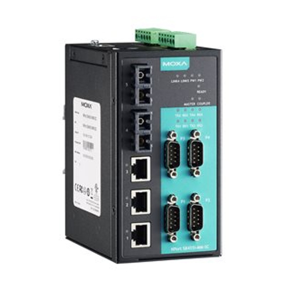
Ethernet switch, which enables easy network operation for your serial devices and connects Ethernet-enabled devices in industrial field applications. The NPort S8000 Series includes seven models: NPort S8455I • Combination switch / device server with 4 RS-232/422/485 ports, 5 10/100M Ethernet ports, RJ45 connector, 12–48 VDC, 0 to 60°C operating temperature... -
Page 7: Overview
NPort S8000 Series Introduction Overview The NPort S8000 is an industrial device server that integrates a managed Ethernet switch with a fully functional serial device server. The NPort S8000 device servers are designed to make your industrial serial devices instantly Internet-ready. The NPort S8458 offers four fiber Ethernet ports, four Ethernet ports, and four RS-232/422/485 serial ports in a single device. -
Page 8: Product Features
2k VDC isolation protection for serial port (the NPort S8455I Series only) • Surge protection for serial/power/Ethernet • Adjustable pull high/low resistor and terminators for the RS-485 port (the NPort S8455I Series only) • 2- or 4-wire RS-485 with patented ADDC™ (Automatic Data Direction Control) -
Page 9: Getting Started
Connecting the Power Connecting to the Network Connecting to a Serial Device LED Indicators Adjustable Pull High/low Resistors and Terminators for the RS-485 Port (NPort S8455I Series only) Wiring the Relay Contact Wiring the Digital Inputs... -
Page 10: Panel Layout
NPort S8000 Series Getting Started Panel Layout... -
Page 11: Dimensions
NPort S8000 Series Getting Started Dimensions NPort S8455 Series... -
Page 12: Nport S8458 Series
NPort S8000 Series Getting Started NPort S8458 Series Connecting the Hardware This section describes how to connect the NPort S8000 to serial devices for initial testing purposes. We cover Wiring Requirements, Connecting the Power, Grounding the NPort S8000, Connecting to the Network, Connecting to a Serial Device, and LED Indicators. -
Page 13: Wiring Requirements
NPort S8000 Series Getting Started Wiring Requirements ATTENTION Safety First! Be sure to disconnect the power cord before installing and/or wiring your NPort S8000. Wiring Caution! Calculate the maximum possible current in each power wire and common wire. Observe all electrical codes dictating the maximum current allowable for each wire size. -
Page 14: Connecting To The Network
Power is off, or power error condition exists. Adjustable Pull High/low Resistors and Terminators for the RS-485 Port (NPort S8455I Series only) In some critical environments, you may need to add termination resistors to prevent the reflection of serial signals. When using termination resistors, it is important to set the pull high/low resistors correctly so that the electrical signal is not corrupted. -
Page 15: Wiring The Relay Contact
NPort S8000 Series Getting Started 3 & 4 Pull High Pull Low Terminator Terminator Terminator 1 KΩ 1 KΩ 120 Ω 100 Ω 55 Ω Default 150 KΩ 150 KΩ – – – ATTENTION Do not set the resistors to 1 KΩ. When using RS-232. Doing so will degrade the RS-232 signals and reduce the effective communication distance. -
Page 16: Wiring The Digital Inputs
NPort S8000 Series Getting Started Wiring the Digital Inputs The NPort 8455I unit has two sets of digital inputs, DI 1 and DI 2. Each DI consists of two contacts of the 6-pin terminal block connector on the NPort 8455I’s top panel. The remaining contacts are used for the NPort 8455I’s two DC inputs. -
Page 17: Initial Ip Address Configuration
Initial IP Address Configuration When setting up the NPort S8000 for the first time, the first thing you should do is configure its IP address. This chapter introduces the different methods that can be used. The following topics are covered in this chapter: ... -
Page 18: Static And Dynamic Ip Addresses
NPort S8000 Series Initial IP Address Configuration Static and Dynamic IP Addresses Determine whether your NPort S8000 needs to use a static IP or dynamic IP address (either DHCP or BOOTP application). • If your NPort S8000 is used in a static IP environment, you will assign a specific IP address using one of the tools described in this chapter. -
Page 19: Ssh Console
NPort S8000 Series Initial IP Address Configuration ATTENTION In order to use the ARP setup method, both your computer and the NPort S8000 must be connected to the same LAN. Alternatively, you may use a crossover Ethernet cable to connect the NPort S8000 directly to your computer’s Ethernet card. - Page 20 NPort S8000 Series Initial IP Address Configuration 2. The console terminal type selection is displayed as shown. Enter the username and password to log in to the SSH console. The default username and password are admin and moxa, respectively. 3. Enter 1 for ansi/vt100 and press ENTER to continue.
- Page 21 NPort S8000 Series Initial IP Address Configuration 4. Press B, or use the arrow keys to select Basic and then press ENTER to configure Basic settings. 5. Press N, or use the arrow keys to select Network and then press ENTER to configure Network parameters.
- Page 22 NPort S8000 Series Initial IP Address Configuration 6. Use the arrow keys to move the cursor to System IP address. Use the Delete, Backspace, or Space key to erase the current IP address, and then type in the new IP address and press Enter. If you are using a dynamic IP configuration (BOOTP or DHCP), you will need to go to the Auto IP configuration field and press Enter to select the appropriate configuration.
-
Page 23: Serial Console
NPort S8000 Series Initial IP Address Configuration Serial Console The NPort S8000 supports configuration through the serial console, which is the same as the Telnet console but accessed through the RS-232 console port rather than through the network. Once you have entered the serial console, the configuration options and instructions are the same as if you were using the Telnet console. - Page 24 NPort S8000 Series Initial IP Address Configuration 6. After you enter the password, or if password protection was not enabled, you will be prompted to select the terminal mode. Press 1 for ansi/vt100 and then press ENTER. 7. Enter the username and password to login to the console. The default username and password are admin and moxa, respectively.
-
Page 25: Choosing The Serial Operation Mode
Choosing the Serial Operation Mode In this chapter, we describe the various serial operation modes of the NPort S8000. The options include an operation mode that uses a driver installed on the host computer and operation modes that rely on TCP/IP socket programming concepts. -
Page 26: Overview
NPort S8000 Series Choosing the Serial Operation Mode Overview The device server function of the NPort S8000 enables network operation of traditional RS-232/422/485 devices, in which a device server is a tiny computer equipped with a CPU, real-time OS, and TCP/IP protocols that can bi-directionally translate data between the serial and Ethernet formats. -
Page 27: Rfc2217 Mode
NPort S8000 Series Choosing the Serial Operation Mode RFC2217 Mode RFC-2217 mode is similar to Real COM mode. That is, a driver is used to establish a transparent connection between a host computer and a serial device by mapping the serial port on the NPort S8000 to a local COM port on the host computer. -
Page 28: Udp Mode
NPort S8000 Series Choosing the Serial Operation Mode UDP Mode Compared to TCP communication, UDP is faster and more efficient. In UDP mode, you can multicast data from the serial device to multiple host computers, and the serial device can also receive data from multiple host computers, making this mode ideal for message display applications. -
Page 29: Use Real Com Mode To Communicate With Serial Devices
Use Real COM Mode to Communicate with Serial Devices The following topics are covered in this chapter: Overview Device Search Utility Installing the Device Search Utility Find a Specific NPort on the Ethernet Network via the DSU ... -
Page 30: Overview
NPort S8000 Series Use Real COM Mode to Communicate with Serial Devices Overview The Documentation & software CD included with your NPort S8000 is designed to make the installation and configuration procedure easy and straightforward. This auto-run CD includes the Device Search Utility (DSU) (to broadcast search for all NPort S8000 accessible over the network and firmware upgrade), NPort driver for Windows and Linux platforms (for COM mapping), and the NPort S8000 User’s Manual. - Page 31 NPort S8000 Series Use Real COM Mode to Communicate with Serial Devices 3. Click Next to install program files to the default directory, or click Browse to select an alternate location. 4. Check the checkbox if you want the DSU to create a desktop icon, or just click Next to install the program's shortcuts in the appropriate Start Menu folder.
- Page 32 NPort S8000 Series Use Real COM Mode to Communicate with Serial Devices 5. Click Next to proceed with the installation. The installer then displays a summary of the installation options. 6. Click Install to begin the installation. The setup window will report the progress of the installation. To change the installation settings, click Back and navigate to the previous screen.
-
Page 33: Find A Specific Nport On The Ethernet Network Via The Dsu
NPort S8000 Series Use Real COM Mode to Communicate with Serial Devices Find a Specific NPort on the Ethernet Network via the DSU The Broadcast Search function is used to locate all the NPort S8000 servers that are connected to the same LAN as your computer. -
Page 34: Opening Your Browser
NPort S8000 Series Use Real COM Mode to Communicate with Serial Devices 2. When the search is complete, all the NPort S8000 servers that were located will be displayed in the DSU window. 3. To modify the configuration of the highlighted NPort S8000, click on the Console icon to open the web console. - Page 35 NPort S8000 Series Use Real COM Mode to Communicate with Serial Devices 3. On the first page of the web console, type admin for the default account name and moxa for the default password. ATTENTION If you use other web browsers, remember to Enable the functions to allow cookies that are stored on your computer or allow per-session cookies.
-
Page 36: Configure Operation Mode To Real Com Mode
NPort S8000 Series Use Real COM Mode to Communicate with Serial Devices ATTENTION Remember to export the configuration file when you have finished the configuration. After using the reset button to load the factory defaults, your configuration can be easily reloaded into the NPort by using the Import function. -
Page 37: Nport Windows Driver Manager
NPort S8000 Series Use Real COM Mode to Communicate with Serial Devices NPort Windows Driver Manager Installing the NPort Windows Driver Manager The NPort Windows Driver Manager is intended for use with NPort S8000 serial ports that are set to Real COM mode. - Page 38 NPort S8000 Series Use Real COM Mode to Communicate with Serial Devices Click Next to install program files to the default directory, or click Browse to select an alternate location. 3. Click Next to install the program’s shortcuts in the appropriate Start Menu folder. 5-10...
- Page 39 NPort S8000 Series Use Real COM Mode to Communicate with Serial Devices 4. Click Next to proceed with the installation. The installer then displays a summary of the installation options. 5. Click Install to begin the installation. The setup window will report the progress of the installation. To change the installation settings, click Back and navigate to the previous screen.
-
Page 40: Using Nport Windows Driver Manager
NPort S8000 Series Use Real COM Mode to Communicate with Serial Devices 6. Click Finish to complete the installation of the NPort Windows Driver Manager. Using NPort Windows Driver Manager After you have installed the NPort Windows Driver Manager, you can set up the NPort S8000’s serial ports as remote COM ports for your PC host. - Page 41 NPort S8000 Series Use Real COM Mode to Communicate with Serial Devices 3. Click Search to search for the NPort device servers. From the list that is generated, select the server to which you will map COM ports, and then click OK. 4.
- Page 42 NPort S8000 Series Use Real COM Mode to Communicate with Serial Devices 5. COM ports and their mappings will appear in blue until they are activated. Activating the COM ports saves the information in the host system registry and makes the COM port available for use. The host computer will not have the ability to use the COM port until the COM ports are activated.
- Page 43 NPort S8000 Series Use Real COM Mode to Communicate with Serial Devices 7. Ports that have been activated will appear in black. 8. Use terminal software to open the mapped COM port to communicate with the serial device. You may download PComm Lite, a useful tool to check the serial communication, from Moxa’s website: http://www.moxa.com/support/download.aspx?type=support&id=167 Configure the mapped COM ports with Advanced Functions...
- Page 44 NPort S8000 Series Use Real COM Mode to Communicate with Serial Devices 1. On the Basic Setting window, use the COM Number drop-down list to select a COM number to be assigned to the NPort S8000’s serial port that is being configured. Select the Auto Enumerating COM Number for Selected Ports option to automatically assign available COM numbers in sequence to selected serial ports.
- Page 45 NPort S8000 Series Use Real COM Mode to Communicate with Serial Devices lower throughput. Classical mode is recommended if you want to ensure that all data is sent out before further processing. FIFO If FIFO is Disabled, the NPort S8000 will transmit one byte each time the Tx FIFO becomes empty, and an Rx interrupt will be generated for each incoming byte.
- Page 46 NPort S8000 Series Use Real COM Mode to Communicate with Serial Devices If you have disabled Fast Flush and find that COM ports mapped to the NPort S8000 perform markedly slower than when using a native COM port, try to verify if “PurgeComm()” functions are used in your application.
-
Page 47: Linux Real Tty Drivers
NPort S8000 Series Use Real COM Mode to Communicate with Serial Devices 5. The IPv6 Settings function is available only for the NPort 6000 series. The NPort S8000 doesn’t support this function. 6. To save the configuration to a text file, select Export from the COM Mapping menu. You will then be able to import this configuration file to another host and use the same COM Mapping settings in the other host. -
Page 48: Hardware Setup
NPort S8000 Series Use Real COM Mode to Communicate with Serial Devices Hardware Setup Before proceeding with the software installation, make sure you have completed the hardware installation. Note that the default IP address for the NPort S8000 is 192.168.127.254, and the default username and password are admin and moxa, respectively. -
Page 49: Removing Mapped Tty Ports
NPort S8000 Series Use Real COM Mode to Communicate with Serial Devices Mapping tty ports manually To map tty ports manually, you may execute mxaddsvr and manually specify the data and command ports, as in the following example: # cd /usr/lib/npreal2/driver # ./mxaddsvr 192.168.3.4 16 4001 966 In this example, 16 tty ports will be added, all with IP 192.168.3.4, with data ports from 4001 to 4016 and command ports from 966 to 981. -
Page 50: Configuring The Unix Driver
NPort S8000 Series Use Real COM Mode to Communicate with Serial Devices 3. Extract the source files from the tar file by executing the command: # tar xvf moxattyd.tar The following files will be extracted: README.TXT moxattyd.c --- source code moxattyd.cf --- an empty configuration file Makefile... - Page 51 NPort S8000 Series Use Real COM Mode to Communicate with Serial Devices Adding an additional server 1. Modify the text file moxattyd.cf to add an additional server. Users may use vi or any text editor to modify the file. For more configuration information, look at the file moxattyd.cf, which contains detailed descriptions of the various configuration parameters.
-
Page 52: Basic Settings And Device Server Configuration
Basic Settings and Device Server Configuration In the following chapters, we will explain how to access the NPort S8000's various configuration, monitoring, and administration functions. There are multiple ways to access these functions: RS-232 console, Telnet/SSH console, and web browser. The serial console connection method, which requires using a serial cable to connect the NPort S8000 to a PC's COM port, can be used if you do not know the NPort S8000's IP address. -
Page 53: Basic Settings
NPort S8000 Series Basic Settings and Device Server Configuration Basic Settings General Settings Server name Setting Factory Default Necessity 1 to 40 characters [model name]_[Serial No.] Optional This column is useful for specifying the application of this NPort device server. Server Location Setting Factory Default... -
Page 54: Time Settings
NPort S8000 Series Basic Settings and Device Server Configuration Time Settings Time The NPort S8000 Series uses SNTP (RFC-1769) for automatic time-calibration, based on information from a time server or user-specified Time and Date information. Functions such as Auto warning “Email” can add real-time information to the message. -
Page 55: Network Settings
NPort S8000 Series Basic Settings and Device Server Configuration End Date Setting Description Factory Default User adjustable date. The End Date parameter allows users to enter the date that None daylight saving time ends. Offset Setting Description Factory Default User adjustable hour. The offset parameter indicates how many hours forward the None clock should be advanced. - Page 56 NPort S8000 Series Basic Settings and Device Server Configuration You must assign a valid IP address to the NPort S8000 before it will work in your network environment. Your network system administrator should provide you with an IP address and related settings for your network. The IP address must be unique within the network (otherwise, the NPort S8000 will not have a valid connection to the network).
- Page 57 NPort S8000 Series Basic Settings and Device Server Configuration DNS IP Address Setting Description Factory Default 1st DNS Server’s The IP address of the DNS Server used by your network. After None IP Address entering the DNS Server’s IP address, you can input the NPort S8000’s URL (e.g., www.NPortS8000.company.com) in your browser’s address field, instead of entering the IP address.
-
Page 58: Serial Settings
NPort S8000 Series Basic Settings and Device Server Configuration Serial Settings Operation Modes Click on Operation Modes, located under Serial Settings, to display serial port settings for four serial ports. To modify serial operation mode settings for a particular port, click on Operation Modes of the serial port in the window on the right-hand side. - Page 59 NPort S8000 Series Basic Settings and Device Server Configuration Port Settings Max connection Setting Factory Default Necessity 1, 2, 3, 4, 5, 6, 7, 8 Required This field is used if you need to receive data from different hosts simultaneously. When set to 1, only one specific host can access this port on the NPort S8000, and the Real COM driver on that host will have full control over the port.
- Page 60 NPort S8000 Series Basic Settings and Device Server Configuration Data Packing Packet length Setting Factory Default Necessity 0 to 1024 Optional Default = 0, The Delimiter Process will be followed, regardless of the length of the data packet. If the data length (in bytes) matches the configured value, the data will be forced out.
- Page 61 NPort S8000 Series Basic Settings and Device Server Configuration Optimal Force Transmit timeout differs according to your application, but it must be at least larger than one character interval within the specified baudrate. For example, assume that the serial port is set to 1200 bps, 8 data bits, 1 stop bit, and no parity.
- Page 62 NPort S8000 Series Basic Settings and Device Server Configuration Delimiter 1 Setting Factory Default Necessity 00 to FF None Optional Delimiter 2 Setting Factory Default Necessity 00 to FF None Optional When Delimiter 1 is enabled, the serial port will clear the buffer and send the data to the Ethernet port when a specific character, entered in a hex format, is received.
- Page 63 NPort S8000 Series Basic Settings and Device Server Configuration If the user wants to send the series of characters in a packet, the serial device attached to the NPort should send characters without time delay larger than Force Transmit timeout between characters and the total length of data must be smaller than or equal to the NPort’s internal buffer size.
- Page 64 NPort S8000 Series Basic Settings and Device Server Configuration ATTENTION The Inactivity time should at least be set larger than that of Force Transmit timeout. To prevent the unintended loss of data due to the session being disconnected, it is highly recommended that this value is set large enough so that the intended data transfer is completed.
- Page 65 NPort S8000 Series Basic Settings and Device Server Configuration Data Packing Packet length Setting Factory Default Necessity 0 to 1024 Optional Default = 0, The Delimiter Process will be followed, regardless of the length of the data packet. If the data length (in bytes) matches the configured value, the data will be forced out.
- Page 66 NPort S8000 Series Basic Settings and Device Server Configuration Optimal Force Transmit timeout differs according to your application, but it must be at least larger than one character interval within the specified baudrate. For example, assume that the serial port is set to 1200 bps, 8 data bits, 1 stop bit, and no parity.
- Page 67 NPort S8000 Series Basic Settings and Device Server Configuration TCP Client Mode Port Settings Inactivity time Setting Factory Default Necessity 0 to 65535 ms 0 ms Optional 0 ms: TCP connection is not closed due to an idle serial line. 0-65535 ms: The NPort automatically closes TCP connection, if there is no serial data activity for the given time.
- Page 68 NPort S8000 Series Basic Settings and Device Server Configuration ATTENTION Inactivity time is ONLY active when “TCP connect on” is set to “Any character.” Ignore jammed IP Setting Factory Default Necessity Enable or Disable Disable Optional Previously, if “max connection” was greater than 1, the serial device was transmitting data, and a connected host was not responding, the NPort would wait until the data was transmitted successfully before transmitting the second group of data to all hosts.
- Page 69 NPort S8000 Series Basic Settings and Device Server Configuration Force transmit Setting Factory Default Necessity 0 to 65535 ms 0 ms Optional 0: Disable the Force Transmit timeout. 1 to 65535: Forces the NPort’s TCP/IP protocol software to try to pack serial data received during the specified time into the same data frame.
- Page 70 NPort S8000 Series Basic Settings and Device Server Configuration ATTENTION The “Destination IP address” parameter can use both IP address and Domain Name. For some applications, the user may need to send the data actively to the remote destination domain name. Designated Local Port 1/2/3/4 Setting Factory Default...
- Page 71 NPort S8000 Series Basic Settings and Device Server Configuration UDP Mode Data Packing Packing length Setting Factory Default Necessity 0 to 1024 Optional Default = 0, The Delimiter Process will be followed, regardless of the length of the data packet. If the data length (in bytes) matches the configured value, the data will be forced out.
- Page 72 NPort S8000 Series Basic Settings and Device Server Configuration Delimiter process Setting Factory Default Necessity Do nothing Do Nothing Optional Delimiter + 1 Delimiter + 2 Strip Delimiter [Delimiter + 1] or [Delimiter + 2]: The data will be transmitted when an additional byte (for Delimiter +1), or an additional 2 bytes (for Delimiter +2) of data is received after receiving the Delimiter.
-
Page 73: Serial Parameters
NPort S8000 Series Basic Settings and Device Server Configuration Local listen port Setting Factory Default Necessity 1 to 65535 4001 Required The UDP port that the NPort listens to, and that other devices must use to contact the NPort. To avoid conflicts with well-known UDP ports, the default is set to 4001. - Page 74 NPort S8000 Series Basic Settings and Device Server Configuration Baud rate Setting Factory Default Necessity 50 bps to 921600 bps 115200 bps Required Select one of the standard baudrates from 50 bps to 921.6 Kbps inthe dropdown box, or select Other and then type the desired baudrate in the input box.
-
Page 75: Serial Tos Settings
NPort S8000 Series Basic Settings and Device Server Configuration Serial ToS Settings Using Serial Traffic Prioritization The NPort S8000’s traffic prioritization capability provides Quality of Service (QoS) to your network by making data delivery more reliable. You can prioritize traffic from both serial interface and Ethernet interface on your network to ensure that high priority data is transmitted with minimum delay. - Page 76 NPort S8000 Series Basic Settings and Device Server Configuration DiffServ Code Point (DSCP) Differentiated Services (DiffServ) Traffic Marking DiffServ is a Layer 3 marking scheme that uses the DiffServ Code Point (DSCP) field in the IP header to store the packet priority information. DSCP is an advanced intelligent method of traffic marking as you can choose how your network prioritizes different types of traffic.
- Page 77 NPort S8000 Series Basic Settings and Device Server Configuration ATTENTION To configure the ToS values, map to the network environment settings for QoS priority service. Please refer to Chapter 7, Ethernet Advanced Settings / Configuring Ethernet Traffic Prioritization / CoS Mapping. 6-26...
-
Page 78: Switch Featured Functions
Switch Featured Functions This chapter explains how to access the NPort S8000’s various configuration, monitoring, and administration functions. There are three ways to access these functions: RS-232 console, Telnet/SSH console, and web browser. The serial console connection method, which requires using a short serial cable to connect the NPort S8000 to a PC’s COM port, can be used if you do not know the NPort S8000’s IP address. -
Page 79: Ethernet Settings
NPort S8000 Series Switch Featured Functions Ethernet Settings Port Settings Enable Setting Description Factory Default Checked Allows data transmission through the port. Enabled Unchecked Immediately shuts off port access. ATTENTION If a connected device or sub-network is wreaking havoc on the rest of the network, the Disable option under Advanced Settings/Port gives the administrator a quick way to shut off access through this port immediately. -
Page 80: Port Trunking
NPort S8000 Series Switch Featured Functions MDI/MDIX Setting Description Factory Default Auto Allows the port to auto detect the port type of the opposing Auto Ethernet device and change the port type accordingly. Choose the MDI or MDIX option if the opposing Ethernet device has trouble auto-negotiating port type. - Page 81 NPort S8000 Series Switch Featured Functions The Port Trunking Settings page is used to assign ports to a Trunk Group. 1. Select Trk1, Trk2 from the Trunk Group drop-down box. 2. Select Static, or LACP from the Trunk Type drop-down box. 3.
-
Page 82: Communication Redundancy
NPort S8000 Series Switch Featured Functions Communication Redundancy Using Communication Redundancy Setting up Communication Redundancy on your network helps protect critical links against failure, protects against network loops, and keeps network downtime at a minimum. The Communication Redundancy function allows the user to set up redundant loops in the network to provide a backup data transmission route in the event that a cable is inadvertently disconnected or damaged. - Page 83 NPort S8000 Series Switch Featured Functions The user does not need to configure any of the NPort S8000 or switches as the master to use Turbo Ring or Turbo Ring V2. If none of the NPort S8000 switches in the ring is configured as the master, then the protocol will automatically assign master status to one of the switches.
- Page 84 NPort S8000 Series Switch Featured Functions Determining the Redundant Path of a “Turbo Ring V2” Ring For a “Turbo Ring V2” ring, the backup segment is the segment connected to the second redundant port on the master. See Configuring “Turbo Ring V2” in the Configuring “Turbo Ring” and “Turbo Ring V2”...
- Page 85 NPort S8000 Series Switch Featured Functions Ring Coupling for a “Turbo Ring V2” Ring Note that the ring coupling settings for a “Turbo Ring V2” ring are different from a “Turbo Ring” ring. For Turbo Ring V2, Ring Coupling is enabled by configuring the “Coupling Port (Primary)” on Switch B, and the “Coupling Port (Backup)”...
- Page 86 NPort S8000 Series Switch Featured Functions Dual-Homing Configuration (applies only to “Turbo Ring V2”) The “dual-homing” option uses a single Ethernet switch to connect two networks. The primary path is the operating connection, and the backup path is a backup connection that is activated in the event that the primary path connection fails.
- Page 87 NPort S8000 Series Switch Featured Functions Redundancy Protocol Setting Description Factory Default Turbo Ring Select this item to change to the Turbo Ring configuration page. Turbo Ring V2 Turbo Ring V2 Select this item to change to the Turbo Ring V2 configuration page.
- Page 88 NPort S8000 Series Switch Featured Functions NOTE When using the Dual-Ring architecture, users must configure settings for both Ring 1 and Ring 2. In this case, the status of both rings will appear under “Current Status.” NOTE The user does not need to set the master to use Turbo Ring. If no master is set, the Turbo Ring protocol will assign master status to one of the NPort S8000 in the ring.
- Page 89 NPort S8000 Series Switch Featured Functions Primary/Backup Port Setting Description Factory Default Primary Port Select any port of the NPort S8000 to be the primary port. port 2 Backup Port Select any port of the NPort S8000 to be the backup port. port 3 The Turbo Chain Concept Moxa’s Turbo Chain is an advanced software technology that gives network administrators the flexibility of...
- Page 90 NPort S8000 Series Switch Featured Functions Configuring “Turbo Chain” Head Switch Configuration Member Switch Configuration Tail Switch Configuration 7-13...
- Page 91 NPort S8000 Series Switch Featured Functions Current Status Now Active Shows which communication protocol is in use: Turbo Ring, Turbo Ring V2, RSTP, Turbo Chain or None. The “Ports Status” indicators show Forwarding for normal transmission, Blocked if this port is connected to the Tail port as a backup path and the path is blocked, and Link down if there is no connection.
-
Page 92: Stp/Rstp
NPort S8000 Series Switch Featured Functions STP/RSTP The STP/RSTP Concept Spanning Tree Protocol (STP) was designed to help reduce link failures in a network and provide protection from loops. Networks that have a complicated architecture are prone to broadcast storms caused by unintended loops in the network. - Page 93 NPort S8000 Series Switch Featured Functions LAN 1 Bridge B LAN 2 Bridge A Bridge C LAN 3 LAN 1 Bridge B LAN 2 Bridge A Bridge C LAN 3 What happens if a link failure is detected? As shown in next figure, the STP process reconfigures the network so that traffic from LAN segment 2 flows through Bridge B.
-
Page 94: Differences Between Rstp And Stp
NPort S8000 Series Switch Featured Functions Port Speed Path Cost 802.1D, 1998 Edition Path Cost 802.1w, 2001 10 Mbps 2,000,000 100 Mbps 200,000 1000 Mbps 20,000 STP Calculation The first step of the STP process is to perform calculations. During this stage, each bridge on the network transmits BPDUs. -
Page 95: Stp Example
NPort S8000 Series Switch Featured Functions STP Example The LAN shown in the following figure has three segments, with adjacent segments connected using two possible links. The various STP factors, such as Cost, Root Port, Designated Bridge Port, and Blocked Port are shown in the figure. -
Page 96: Configuring Stp/Rstp
NPort S8000 Series Switch Featured Functions Configuring STP/RSTP The following figures indicate which Spanning Tree Protocol parameters can be configured. A more detailed explanation of each parameter follows. Redundancy Protocol Setting Description Factory Default Turbo Ring Select this item to change to the Turbo Ring configuration page. Turbo Ring 2 Select this item to change to the Turbo Ring 2 configuration page. -
Page 97: Configuration Limits Of Stp/Rstp
NPort S8000 Series Switch Featured Functions Max. Age (sec.) Setting Description Factory Default Numerical value input If this device is not the root, and it has not received a hello by user message from the root in an amount of time equal to “Max. Age,”... -
Page 98: Bandwidth Management
NPort S8000 Series Switch Featured Functions Bandwidth Management Using Bandwidth Management In general, one host should not be allowed to occupy unlimited bandwidth, particularly when the device malfunctions. For example, so-called “broadcast storms” could be caused by an incorrectly configured topology, or a malfunctioning device. -
Page 99: Configuring Line-Swap Fast Recovery
NPort S8000 Series Switch Featured Functions Configuring Line-Swap Fast Recovery To disable the Line-Swap Fast Recovery function, or to re-enable the function after it has already been disabled, access either the Console utility’s Line-Swap recovery page, or the Web Browser interface’s Line-Swap fast recovery page, as the following figure shows: Enable Line-Swap-Fast-Recovery Setting... -
Page 100: The Traffic Prioritization Concept
NPort S8000 Series Switch Featured Functions The Traffic Prioritization Concept What is Traffic Prioritization? Traffic prioritization allows you to prioritize data so that time-sensitive and system-critical data can be transferred smoothly and with minimal delay over a network. The benefits of using traffic prioritization are: •... -
Page 101: Configuring Ethernet Traffic Prioritization
NPort S8000 Series Switch Featured Functions Differentiated Services (DiffServ) Traffic Marking DiffServ is a Layer 3 marking scheme that uses the DiffServ Code Point (DSCP) field in the IP header to store the packet priority information. DSCP is an advanced intelligent method of traffic marking as you can choose how your network prioritizes different types of traffic. - Page 102 NPort S8000 Series Switch Featured Functions QoS Classification The NPort S8000 supports inspection of layer 3 TOS and/or layer 2 CoS tag information to determine how to classify traffic packets. Queuing Mechanism Setting Description Factory Default Weighted Fair The NPort S8000 has four priority queues. In the weighted fair Weight Fair scheme, an 8, 4, 2, 1 weighting is applied to the four priorities.
- Page 103 NPort S8000 Series Switch Featured Functions NOTE The priority of an ingress frame is determined in order by: Inspect TOS Inspect CoS Port Highest Priority NOTE The designer can enable these classifications individually or in combination. For instance, if a ‘hot,’ higher priority port is required for a network design, “Inspect TOS”...
-
Page 104: Virtual Lan
NPort S8000 Series Switch Featured Functions ToS/DiffServ Mapping Setting Description Factory Default Set the mapping table of different TOS values to four different 1 to 16: Low Normal egress queues. 17 to 32: Normal Medium 33 to 48: Medium High 49 to 64: High Virtual LAN Using Virtual LAN... - Page 105 NPort S8000 Series Switch Featured Functions Switch A Backbone connects multiple switches Switch B Department 1 VLAN 1 Department 2 VLAN 2 Department 3 VLAN 3 Benefits of VLANs The main benefit of VLANs is that they provide a network segmentation system that is far more flexible than traditional networks.
- Page 106 NPort S8000 Series Switch Featured Functions All the ports are initially placed on this VLAN, and it is the only VLAN that allows you to access the management software of the NPort S8000 over the network. Communication Between VLANs If devices connected to a VLAN need to communicate to devices on a different VLAN, a router or Layer 3 switching device with connections to both VLANs needs to be installed.
- Page 107 NPort S8000 Series Switch Featured Functions The following section illustrates how to use these ports to set up different applications. Sample Applications of VLANs using the NPort S8000 In this application: • Port 1 connects a single untagged device and assigns it to VLAN 5; it should be configured as “Access Port” with PVID 5.
-
Page 108: Configuring Virtual Lan
NPort S8000 Series Switch Featured Functions • Packets from device E will travel through “Trunk Port 3” with tagged VID 4. Switch B will recognize its VLAN, pass it to port 7, and then remove tags received successfully by device I. Packets from device I will travel through “Trunk Port 3”... - Page 109 NPort S8000 Series Switch Featured Functions Fixed VLAN List (Tagged) Setting Description Factory Default VID range from 1 to This field will be active only when selecting the “Trunk” port None 4094 type. Set the other VLAN ID for tagged devices that connect to the “Trunk”...
-
Page 110: Multicast Filtering
NPort S8000 Series Switch Featured Functions Multicast Filtering Using Multicast Filtering Multicast filtering improves the performance of networks that carry multicast traffic. This section explains multicasts, multicast filtering, and how multicast filtering can be implemented on your NPort S8000. The Concept of Multicast Filtering What is an IP Multicast? A multicast is a packet sent by one host to multiple hosts. - Page 111 NPort S8000 Series Switch Featured Functions Multicast Filtering Multicast filtering ensures that only end-stations that have joined certain groups receive multicast traffic. With multicast filtering, network devices only forward multicast traffic to the ports that are connected to registered end-stations. The following two figures illustrate how a network behaves without multicast filtering and with multicast filtering.
-
Page 112: Configuring Igmp Snooping
NPort S8000 Series Switch Featured Functions Multicast Filtering and Moxa Switching Device Server The NPort S8000 has three ways to achieve multicast filtering: IGMP (Internet Group Management Protocol) Snooping, GMRP (GARP Multicast Registration Protocol), and adding a static multicast MAC manually to filter multicast traffic automatically IGMP Multicast Filtering IGMP is used by IP-supporting network devices to register hosts with multicast groups. -
Page 113: Igmp Snooping Settings
NPort S8000 Series Switch Featured Functions IGMP Snooping Settings IGMP Snooping Enable Setting Description Factory Default Enable/Disable Select the option to enable the IGMP Snooping function Disabled globally. Query Interval Setting Description Factory Default Numerical value input Set the query interval of the Querier function globally. Valid 125 seconds by user settings are from 20 to 600 seconds. - Page 114 NPort S8000 Series Switch Featured Functions Static Multicast MAC Some devices may only support multicast packets, but not support either IGMP Snooping or GMRP. The NPort S8000 supports adding multicast groups manually to enable multicast filtering. Add New Static Multicast Address to the List Setting Description Factory Default...
-
Page 115: Configuring Gmrp
NPort S8000 Series Switch Featured Functions Configuring GMRP GMRP is a MAC-based multicast management protocol, whereas IGMP is IP-based. GMRP provides a mechanism that allows bridges and end stations to register or deregister Group membership information dynamically. GMRP enable Setting Description Factory Default Enable/Disable... -
Page 116: Configuring Set Device Ip
NPort S8000 Series Switch Featured Functions Perform the following steps to use the Set device IP function: 1. set up the connected devices Set up those Ethernet-enabled devices connected to the NPort S8000 for which you would like IP addresses to be assigned automatically. -
Page 117: System Management
NPort S8000 Series Switch Featured Functions When Option 82 is enabled on the switch, a subscriber device is identified by the switch port through which it connects to the network (in addition to its MAC address). Multiple hosts on the subscriber LAN can be connected to the same port on the access switch and are uniquely identified. -
Page 118: Syslog Server
NPort S8000 Series Switch Featured Functions Accessible IP Settings allows you to add or remove “Legal” remote host IP addresses to prevent unauthorized access. Access to the NPort S8000 is controlled by IP address. If a host’s IP address is in the accessible IP table, then the host will be allowed access to the NPort S8000. - Page 119 NPort S8000 Series Switch Featured Functions Syslog Server 1 Setting Description Factory Default IP Address Enter the IP address of 1st Syslog Server used by your None network. Port Destination Enter the UDP port of 1st Syslog Server. (1 to 65535) Syslog Server 2 Setting Description...
-
Page 120: Local User Database
NPort S8000 Series Switch Featured Functions Local User Database Local User Database Setup The User Database may be used for to authenticate users for 802.1x access and is useful if you do not have an external RADIUS server for authentication. The User Table allow to stores up to 32 entries, with fields for User Name, Password, and Description. - Page 121 NPort S8000 Series Switch Featured Functions client that requests access to the port. The client is only allowed access to the port if the client’s permission is authenticated. The IEEE 802.1X Concept Three components are used to create an authentication mechanism based on 802.1X standards: Client/Supplicant, Authentication Server, and Authenticator.
-
Page 122: Configuring Static Port Lock
NPort S8000 Series Switch Featured Functions failure to the authenticator if the Local User Database is used. The authenticator sends an “EAP-Failure” frame to the supplicant. 3. The RADIUS server sends a “RADIUS Access-Challenge,” which contains an “EAP Request” with an authentication type to the authenticator to ask for the password from the client. -
Page 123: Configuring Ieee 802.1X
NPort S8000 Series Switch Featured Functions Configuring IEEE 802.1X Database Option Setting Description Factory Default Local Select this option when setting the Local User Database as the Local (Max. 32 users) authentication database. Radius Select this option to set an external RADIUS server as the Local authentication database. -
Page 124: Auto Warning Settings
NPort S8000 Series Switch Featured Functions Re-Auth Period Setting Description Factory Default Numerical Specify how frequently the end stations need to reenter 3600 (60-65535 sec.) usernames and passwords in order to stay connected. Server Port Setting Description Factory Default Numerical The UDP port of the RADIUS Server 1812 Shared Key... - Page 125 NPort S8000 Series Switch Featured Functions Mail Server IP/Name Setting Description Factory Default IP address The IP Address of your email server. None Account Name Setting Description Factory Default Max. 45 Characters Your email account name (typically your user name) None Account Password Setting...
-
Page 126: Configuring Snmp
NPort S8000 Series Switch Featured Functions Configuring SNMP The NPort S8000 supports SNMP V1/V2c/V3. SNMP V1, and SNMP V2c use a community string match for authentication, which means that SNMP servers access all objects with read-only or read/write permissions using the community string public/private (default value). SNMP V3, which requires you to select an authentication level of MD5 or SHA, is the most secure protocol. -
Page 127: Snmp Read/Write Settings
NPort S8000 Series Switch Featured Functions SNMP Read/Write Settings SNMP agent version: The NPort S8000 supports SNMP V1, V2c, and V3. V1, V2c Read community (default=public): This is a text password mechanism that is used to weakly authenticate queries to agents of managed network devices. V1, V2c Write/Read community (default=private): This is a text password mechanism that is used to weakly authenticate changes to agents of managed network devices. -
Page 128: E-Mail Event Settings
NPort S8000 Series Switch Featured Functions Read/write Privacy: Use this field to define the encryption key for the specified level of access. Read only: Read only authentication mode allows you to configure the authentication mode for read/write access. For each level of access, you may configure the following: Read/only User name: Use this optional field to identify the user name for the specified level of access. - Page 129 NPort S8000 Series Switch Featured Functions System Events Warning e-mail is sent when… DI1 (OffOn) Digital Input 1 is triggered by off to on transition DI2 (OnOff) Digital Input 2 is triggered by on to off transition DI2 (OffOn) Digital Input 2 is triggered by off to on transition Configuration Change A configuration item has been changed.
-
Page 130: Snmp Trap
NPort S8000 Series Switch Featured Functions SNMP Trap System Events Warning e-mail is sent when… System Cold Start Power is cut off and then reconnected. System Warm Start The NPort S8000 is rebooted, such as when network parameters are changed (IP address, subnet mask, etc.). -
Page 131: Relay Alarm Settings
NPort S8000 Series Switch Featured Functions Ethernet Port Events Warning e-mail is sent when… Link-ON The port is connected to another device. Link-OFF The port is disconnected (e.g., the cable is pulled out, or the opposing device shuts down). Traffic-Overload The port’s traffic surpasses the Traffic-Threshold for that port (provided this item is Enabled). -
Page 132: System Log Settings
NPort S8000 Series Switch Featured Functions Override relay alarm settings Select this option to override the relay warning setting temporarily. Releasing the relay output will allow administrators to fix any problems with the warning condition. System Events Factory Default Override relay 1 Warning settings Non-check Override relay 2 Warning settings Non-check... - Page 133 NPort S8000 Series Switch Featured Functions Local Log Keep the log into the flash of NPort S8000 up to 512 items. Remote Log Keep the log into the remote defined Log Server. You will need to assign a remote Log Server in the System Management / Misc.
-
Page 134: Maintenance
NPort S8000 Series Switch Featured Functions Maintenance Console Settings Config HTTP console HTTP console enable/disable HTTPS console HTTPS console enable/disable Telnet console Telnet console enable/disable SSH console SSH console enable/disable Reset button Always Enable Reset button disable after 60 sec uptime Auto refresh time Monitor page refresh time Ping... -
Page 135: Update System Files From Local Pc
NPort S8000 Series Switch Featured Functions Update System Files from Local PC The NPort S8000 supports different types of files that can be uploaded to or downloaded from the device. In this section, you will learn the details of the different types of files, such as log file, configuration file or firmware file, and how to import/export them from the NPort S8000. - Page 136 NPort S8000 Series Switch Featured Functions Load Import/Export Configuration File To export the configuration file of this NPort S8000, click Export to save it to the local host. Log File To export the Log file of this NPort S8000, click Export and save it to the local host. NOTE Some operating systems will open the configuration file and log file directly in the web page.
-
Page 137: Load Factory Default
NPort S8000 Series Switch Featured Functions Backup Media You can use Moxa's Automatic Backup Configurator (ABC-01) to save and load the NPort S8000's configurations through NPort S8000's RS-232 console port. You may find more details about ABC-01 at: http://www.moxa.com/product/Automatic_Backup_Configurator_ABC-01.htm. Load Factory Default This function will reset all of NPort S8000’s settings to the factory default values. -
Page 138: Change Password
NPort S8000 Series Switch Featured Functions NOTE After activating the Factory Default function, you will need to use the default network settings to re-establish a web-browser or Telnet connection with your NPort S8000. Change Password For all changes to the NPort S8000’s password protection settings, you will first need to enter the old password. Leave this blank if you are setting up password protection for the first time. -
Page 139: Tftp Settings
NPort S8000 Series Switch Featured Functions 1. Configure the EDS’s Mirror Port function from either the Console utility or Web Browser interface. You will need to configure three settings: Monitored Port Select the port number of the port whose network activity will be monitored. Mirror Port Select the port number of the port that will be used to monitor the activity of the monitored port. -
Page 140: Dip Switch Settings
NPort S8000 Series Switch Featured Functions Firmware Files Path and Name Setting Description Factory Default Max. 40 Characters The path and file name of the NPort S8000’s firmware file. None Log Files Path and Name Setting Description Factory Default Max. 40 Characters The path and file name of the NPort S8000’s log file None After setting up the desired path and file name, click Activate to save the setting, and then click Download to... - Page 141 NPort S8000 Series Switch Featured Functions Set DIP switch as Turbo Ring / Set DIP switch as Turbo Ring V2 Setting Description Factory Default Set DIP switch as Turbo Select this option to enable the Turbo Ring DIP switches to This is the default if Ring configure the NPort S8000 for a “Turbo Ring”...
-
Page 142: System Monitoring
NPort S8000 Series Switch Featured Functions NOTE The DIP 1 setting will only be active if DIP 3 is in the ON position. If you set DIP 3 to OFF, then the default Ring Coupling port will NOT be enabled, even if DIP 1 is ON. NOTE The Turbo Ring Ports and Coupling Ports will be added automatically to all VLANs if you set DIP Switch 4 to the “ON”... -
Page 143: Serial Port Status
NPort S8000 Series Switch Featured Functions Serial Port Status Go to Serial Port Status under Serial Status to view the current status of each serial port. Serial Port Status Buffering. Monitor port buffering usage (bytes) of each serial port. Serial Port Error Count Go to Serial Port Error Count under Serial Status to view the error count for each serial port. -
Page 144: System Status
NPort S8000 Series Switch Featured Functions System Status System Information This page illustrate the status of system Light Status Default Power Lighting when power is NO blind Lighting when triggered blind DIP Switch Lighting when DIP switch Set to ON blind Network Connections Go to Network Connections under System Status to view network connection information. -
Page 145: Ethernet Status
NPort S8000 Series Switch Featured Functions Event Log Bootup This field shows how many times the NPort S8000 has been rebooted or cold started. Date The date is updated based on how the current date is set in the “Basic Setting” page. Time The time is updated based on how the current time is set in the “Basic Setting”... - Page 146 NPort S8000 Series Switch Featured Functions The MAC Address table can be configured to display the following NPort S8000 MAC address groups. Select this item to show all NPort S8000 MAC addresses ALL Learned Select this item to show all NPort S8000 Learned MAC addresses ALL Static Lock Select this item to show all NPort S8000 Static Lock MAC addresses ALL Static...
- Page 147 NPort S8000 Series Switch Featured Functions 802.1X Reauth The NPort S8000 can force connected devices to be re-authorized manually. Port Access Control Table The port status will indicate whether the access is authorized or unauthorized. Warning List Use this table to see if any relay alarms have been issued. Ethernet Monitor This page illustrates the data transmission status of Ethernet.
- Page 148 NPort S8000 Series Switch Featured Functions Check the Port Status to show the status of Ethernet port. Trunk Table Setting Description Trunk Group Displays the Trunk Type and Trunk Group. Member Port Display which member ports belong to the trunk group. Status Success means port trunking is working properly.
-
Page 149: Turbo Ring
NPort S8000 Series Switch Featured Functions Explanation of “Current Status” Items Now Active Shows which communication protocol is in use: Turbo Ring, Turbo Ring V2, RSTP Ring 1/2—Status Shows Healthy if the ring is operating normally, and shows Break if the ring’s backup link is active. Ring 1/2—Master/Slave Indicates whether or not this NPort S8000 is the Master of the Turbo Ring. -
Page 150: Restart
NPort S8000 Series Switch Featured Functions Turbo Ring 2 Now Active Indicate the in used communication protocol. It may be Turbo Ring, Turbo Ring V2, RSTP, or none. Ring 1/2 Status Healthy The ring is operating normally Break The backup link is active in the Ring. Master/Slave Indicate NPort S8000 is in the Master mode or Slave mode of the Turbo Ring 2. -
Page 151: Restart Serial Port
NPort S8000 Series Switch Featured Functions Restart Serial Port Go to Restart Ports under Restart and then select the ports to be restarted. Click Select All to select all the ports. Click Submit to restart the selected ports. 7-74... -
Page 152: Pinouts And Cable Wiring
Pinouts and Cable Wiring In this appendix, we cover the following topics. Port Pinout Diagrams Ethernet Port Pinouts Serial Port Pinouts Cable Wiring Diagrams Ethernet Cables... -
Page 153: Port Pinout Diagrams
NPort S8000 Series Pinouts and Cable Wiring Port Pinout Diagrams Ethernet Port Pinouts Signal Serial Port Pinouts DB9 Male RS-232 Port Pinouts RS-232 Signal DCD (in) RxD (in) TxD (out) DTR (out) DSR (in) RTS (out) CTS (in) – Serial Console Port Pinouts RJ45 N.C. -
Page 154: Cable Wiring Diagrams
NPort S8000 Series Pinouts and Cable Wiring Cable Wiring Diagrams Ethernet Cables... -
Page 155: Well-Known Port Numbers
Well-Known Port Numbers This appendix is for your reference about the Well Known port numbers that may cause network problem if you set the NPort into the same port. Refer to RFC 1700 for Well Known port numbers of refer to the following introduction from the IANA. - Page 156 NPort S8000 Series Well-Known Port Numbers TCP Socket Application Service reserved TCP Port Service Multiplexor Management Utility Echo Discard Active Users (systat) Daytime Netstat FTP data port FTP CONTROL port Telnet SMTP (Simple Mail Transfer Protocol) Time (Time Server) Host name server (names server) Whois (nickname) (Login Host Protocol) (Login) TCP Socket...
- Page 157 SNMP Agents with MIB II & RS-232 Like Groups The NPort S8000 has built-in SNMP (Simple Network Management Protocol) agent software. The following table lists the proprietary MIB-II group, as well as the variable implementation for the NPort S8000. Moxa-NPort S8000-MIB overview basicSetting portSetting...
- Page 158 NPort S8000 Series SNMP Agents with MIB II & RS-232 Like Groups overview basicSetting portSetting ethernetSetting tcpClientDestinationAddress2 turboRingRdntPort2 tcpClientDestinationPort2 turboRingEnableCoupling tcpClientDestinationAddress3 turboRingCouplingPort tcpClientDestinationPort3 turboRingControlPort tcpClientDestinationAddress4 turboRingV2 tcpClientDestinationPort4 turboRingV2Ring1 tcpClientDesignatedLocalPort1 ringIndexRing1 tcpClientDesignatedLocalPort2 ringEnableRing1 tcpClientDesignatedLocalPort3 masterSetupRing1 tcpClientDesignatedLocalPort4 rdnt1stPortRing1 tcpClientConnectionControl rdnt2ndPortRing1 turboRingV2Ring2 udpTable ringIndexRing2 udpEntry ringEnableRing2...
-
Page 159: Snmp Agents With Mib Ii & Rs-232 Like Groups
NPort S8000 Series SNMP Agents with MIB II & RS-232 Like Groups overview basicSetting portSetting ethernetSetting serialTosTable serialTosEntry ethernetAdvSetting systemManagement trafficPrioritization miscNetwork qosClassification accessibleIP queuingMechanism enableAccessibleIP qosPortTable accessibleIpEntry qosPortEntry accessibleIpIndex inspectTos accessibleIpAddress inspectCos accessibleIpNetMask portPriority syslogSetting cosMapping syslogServer1 cosMappingTable syslogServer1port cosMappingEntry syslogServer2 cosTag... - Page 160 NPort S8000 Series SNMP Agents with MIB II & RS-232 Like Groups ethernetAdvSetting systemManagement gmrpSettingEntry emailWarningEventDiTable enableGMRP emailWarningEventDiEntry setDeviceIp emailWarningEventDiInputOn2Off setDevIpTable emailWarningEventDiInputOff2On setDevIpEntry emailWarningEventConfigChange setDevIpIndex emailWarningEventAuthFail setDevIpCurrentIpofDevice emailWarningEventTopologyChanged setDevIpPresentBy emailWarningEventSerialPortTable setDevIpDedicatedIp emailWarningEventSerialPortEntry emailWarningEventSerailDCDChange emailWarningEventSerailDSRChange emailWarningEventEthernetPortTable emailWarningEventEthernetPortEntry emailWarningEventEthernetPortLinkOn emailWarningEventEthernetPortLinkOff emailWarningEventEthernetPortTrafficOverload emailWarningEventEthernetPortTrafficThreshold emailWarningEventEthernetPortTrafficDuration snmpWarningEventType snmpWarningEventServerColdStart...
- Page 161 NPort S8000 Series SNMP Agents with MIB II & RS-232 Like Groups ethernetAdvSetting systemManagement relayWarningTurboRingBreakStatus portRelayWarningTable portRelayWarningEntry relayWarningLinkChanged relayWarningLinkChangedStatus relayWarningTrafficOverload relayWarningTrafficOverloadStatus relayWarningTrafficThreshold relayWarningTrafficDuration diRelayWarningTable diRelayWarningEntry relayWarningDiInputChanged relayWarningDiInputChangedStatus sysLogSettings sysLocalLog networkLocalLog configLocalLog opModeLocalLog sysRemoteLog networkRemoteLog configRemoteLog opModeRemoteLog maintenance consoleSetting webConsole httpConsole telnetConsole resetButtonFunction autoRefresh...
- Page 162 NPort S8000 Series SNMP Agents with MIB II & RS-232 Like Groups systemMonitoring restart monitorSerialPortStatusTable monitorSerialPortStatusEntry monitorTxCount monitorRxCount monitorTxTotalCount monitorRxTotalCount monitorDSR monitorDTR monitorRTS monitorCTS monitorDCD serialPortErrorCount monitorSerialPortErrorCountTable monitorSerialPortErrorCountEntry monitorErrorCountFrame monitorErrorCountParity monitorErrorCountOverrun monitorErrorCountBreak serialPortSettings monitorSerialPortSettingsTable monitorSerialPortSettingsEntry monitorBaudRate monitorDataBits monitorStopBits monitorParity monitorRTSCTSFlowControl monitorXONXOFFFlowControl monitorFIFO monitorInterface...
- Page 163 NPort S8000 Series SNMP Agents with MIB II & RS-232 Like Groups systemMonitoring restart igmpstatus igmpSnoopingMulticastGroupTable igmpSnoopingMulticastGroupEntry learnedMulticastQuerierPorts igmpSnoopingIpGroup igmpSnoopingMacGroup igmpSnoopingJoinedPorts gmrpStatus gmrpTable gmrpEntry gmrpMulticastGroup gmrpFixedPorts gmrpLearnedPorts dot1XReauth dot1xReauthTable dot1xReauthEntry dot1xReauthPortIndex dot1xReauth portAccessControlList portAccessControlTable portAccessControlEntry portAccessControlAddress portAccessControlPortNo portAccessControlAccessStatus portAccessControlStatus warningList warningListTable warningListEntry warningListIndex...
- Page 164 NPort S8000 Series SNMP Agents with MIB II & RS-232 Like Groups systemMonitoring restart ethernetMonitorRxErrOversize ethernetMonitorRxErrJabber ethernetMonitorReset monitorPortTable monitorPortEntry monitorLinkStatus monitorSpeed monitorFDXFlowCtrl monitorAutoMDI monitorConnectedIP monitorTraffic trunkTableList trunkTable trunkEntry trunkIndex trunkPort trunkStatus vlanList vlanTable vlanEntry vlanId joinedAccessPorts joinedTrunkPorts commRedStatus activeProtocolOfRedundancy spanningTreeStatus spanningTreeRoot spanningTreeStatusTable spanningTreeStatusEntry...
- Page 165 NPort S8000 Series SNMP Agents with MIB II & RS-232 Like Groups systemMonitoring restart rdnt1stPortStatusRing2 rdnt2ndPortStatusRing2 brokenStatusRing2 turboRingV2CouplingStatus coupling1stPortStatus coupling2ndPortStatus...
-
Page 166: Switch Mib Groups
Switch MIB Groups The NPort S8000 comes with built-in SNMP (Simple Network Management Protocol) agent software that supports cold/warm start trap, line up/down trap, and RFC 1213 MIB-II. The standard MIB groups supported by the NPort S8000 are: MIB II.1 – System Group sysORTable MIB II.2 –... -
Page 167: System Events
NPort S8000 Series Switch MIB Groups dot1dTpHCPortTable dot1dTpPortOverflowTable pBridgeMIB dot1dExtBase dot1dPriority dot1dGarp qBridgeMIB dot1qBase dot1qTp dot1qFdbTable dot1qTpPortTable dot1qTpGroupTable dot1qForwardUnregisteredTable dot1qStatic dot1qStaticUnicastTable dot1qStaticMulticastTable dot1qVlan dot1qVlanCurrentTable dot1qVlanStaticTable dot1qPortVlanTable The NPort S8000 also provides a private MIB file, located in the file “Moxa-NPort S8000-MIB.my” or “Moxa-NPort S8000-MIB.my”... - Page 168 NPort S8000 Series Switch MIB Groups Serial Port Events 1. DCD changed 2. DSR changed Ethernet Port Events 1. Link-ON 2. Link-OFF 3. Traffic-Overload 4. Traffic-Threshold(%) 5. Traffic-Duration(s)
-
Page 169: Compliance Note
Compliance Note This product complies with Chinese RoHS (Restriction of Hazardous Substances) regulations for Electronic Information Products. CE Warming This is a Class A product. In a domestic environment, this product may cause radio interference in which case the user may be required to take appropriate measures. Federal Communications Commission Statement FCC –...
Need help?
Do you have a question about the NPort S8455I and is the answer not in the manual?
Questions and answers