Moxa Technologies NPort W2250A Series User Manual
Hide thumbs
Also See for NPort W2250A Series:
- User manual (142 pages) ,
- Quick installation manual (7 pages) ,
- Tech note (5 pages)

Related Manuals for Moxa Technologies NPort W2250A Series


Summary of Contents for Moxa Technologies NPort W2250A Series
- Page 1 NPort W2150A/W2250A Series User’s Manual Edition 10.1, September 2018 www.moxa.com/product © 2018 Moxa Inc. All rights reserved.
- Page 2 NPort W2150A/W2250A Series User’s Manual The software described in this manual is furnished under a license agreement and may be used only in accordance with the terms of that agreement. Copyright Notice © 2018 Moxa Inc. All rights reserved. Trademarks The MOXA logo is a registered trademark of Moxa Inc.
-
Page 3: Table Of Contents
Table of Contents Introduction ............................1-1 Overview ............................1-2 Package Checklist ..........................1-2 Product Features ..........................1-3 Serial Port Pin Assignments ........................1-3 Getting Started..........................2-1 Overview ............................2-2 Panel Layout ............................2-2 LED Indicators ............................ 2-3 Top Panel LED Indicators ......................2-3 End Panel LED Indicators ......................2-3 Pull High/Low Resistors for RS-422/485 .................... - Page 4 Serial Port Settings ........................8-2 Communication Parameters ......................8-21 Data Buffering/Log ........................8-22 Web Console: System Management ....................9-1 Overview ............................9-2 System Management ...........................9-2 Misc. Network Settings .........................9-2 Auto Warning Settings .........................9-6 Maintenance ..........................9-10 Certificate ..........................9-14 10. Web Console: System Monitoring ....................10-1 Overview ............................
-
Page 5: Introduction
Introduction The following topics are covered in this chapter: Overview Package Checklist Product Features Serial Port Pin Assignments... -
Page 6: Overview
NPort W2150A/W2250A Series Introduction Overview In this chapter, we introduce the basic features and specifications of the NPort W2150A/W2250A and NPort W2150A/W2250A-T, referred to collectively as the NPort W2150A/W2250A Series. The NPort W2150A/W2250A Series of wireless device servers are used to connect RS-232/422/485 serial devices or Ethernet devices, including PLCs, meters, and sensors, to a wireless LAN. -
Page 7: Product Features
NPort W2150A/W2250A Series Introduction Product Features • Supports wireless client: links any serial or Ethernet device to an IEEE 802.11a/b/g/n network • Web-based configuration over Ethernet or WLAN • Enhanced remote configuration with HTTPS, SSH • Secure data access with WEP, WPA, WPA2 •... -
Page 8: Getting Started
Getting Started The following topics are covered in this chapter: Overview Panel Layout LED Indicators Top Panel LED Indicators End Panel LED Indicators Pull High/Low Resistors for RS-422/485 Placement Options Connecting the Hardware Connecting to the Network Connecting the Power Connecting to a Serial Device... -
Page 9: Overview
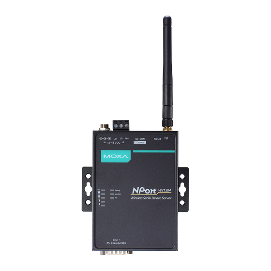
NPort W2150A/W2250A Series Getting Started Overview This chapter presents the hardware features of the NPort W2150/W2250A Series and explains how to connect the hardware. Panel Layout NPort W2150A/W2150A-T NPort W2250A/W2250A-T... -
Page 10: Led Indicators
NPort W2150A/W2250A Series Getting Started LED Indicators Top Panel LED Indicators Name Color Function Steady on: Power is on, and the NPort is booting up. Blinking: An IP conflict exists, or the DHCP/ BOOTP server did not respond properly. Ready Steady on: The NPort is functioning normally. -
Page 11: Pull High/Low Resistors For Rs-422/485
NPort W2150A/W2250A Series Getting Started Pull High/Low Resistors for RS-422/485 You may need to set the pull high/low resistors when termination resistors are used for certain RS-422 or RS-485 environments. S2 (Serial 1) DIP 1 DIP 2 DIP 3 DIP 4 S3 (Serial 2) Pull high resistor Pull low resistor... -
Page 12: Placement Options
NPort W2150A/W2250A Series Getting Started Placement Options The NPort can be placed on a desktop or other horizontal surface. You can also install the NPort on a DIN- rail or on the wall. Wall Mounting DIN-Rail Mounting Connecting the Hardware ATTENTION Before connecting the hardware, follow these important wiring safety precautions: Disconnect power source... -
Page 13: Connecting To The Network
NPort W2150A/W2250A Series Getting Started Connecting to the Network Use the supplied Ethernet cable to connect the NPort to your Ethernet network. If the cable is properly connected, the NPort will indicate a valid connection to the Ethernet as follows: •... -
Page 14: Initial Ip Configuration
Initial IP Configuration The following topics are covered in this chapter: Overview Factory Default IP Settings Using ARP to Assign an IP Address Using the Telnet Console to an Assign IP Address Using the Serial Console to an Assign IP Address... -
Page 15: Overview
NPort W2150A/W2250A Series Initial IP Configuration Overview This chapter presents several ways to assign the NPort’s IP address for the first time. Please refer to Chapter 2 for instructions on connecting to the network. The web console is the recommended method for configuring the NPort. Please refer to Chapter 5 and 6 for details on using the web console for configuration. -
Page 16: Using The Telnet Console To An Assign Ip Address
NPort W2150A/W2250A Series Initial IP Configuration 5. You will see a message indicating that the connection failed. The NPort will automatically reboot with the new IP address. You can verify that the configuration was successful by connecting to the new IP address with Telnet, ping, the web console, or the Device Search Utility (DSU). - Page 17 NPort W2150A/W2250A Series Initial IP Configuration 4. You will login to the Overview page. 5. Press N or use the cursor keys to select Network and press ENTER. 6. Press E or use the cursor keys to select Ethernet and press ENTER.
- Page 18 NPort W2150A/W2250A Series Initial IP Configuration 7. Use the cursor keys to navigate between the different fields. For IP address, Netmask, and Gateway, enter the desired values directly. For IP configuration and LAN speed, press ENTER to open a submenu and select between the available options. 8.
-
Page 19: Using The Serial Console To An Assign Ip Address
NPort W2150A/W2250A Series Initial IP Configuration The NPort will reboot with the new IP settings. You can telnet to the new IP to login again. Using the Serial Console to an Assign IP Address Before using the NPort’s serial console, turn off the power and use a serial cable to connect the NPort console port to your computer’s serial port. - Page 20 NPort W2150A/W2250A Series Initial IP Configuration 4. In your terminal emulator program, set the terminal type to ANSI or VT100. If you select Dumb Terminal as the terminal type, some of the console functions—especially the “Monitor” function—may not work properly. 5.
- Page 21 NPort W2150A/W2250A Series Initial IP Configuration 6. The serial console will open and will be functionally identical to the Telnet console. Please refer to the Telnet console section for instructions on how to navigate the console and configure the IP settings.
-
Page 22: Introduction To Operation Modes
Introduction to Operation Modes The following topics are covered in this chapter: Overview Real COM Mode RFC2217 Mode TCP Server Mode TCP Client Mode UDP Mode Pair Connection Modes Ethernet Modem Mode... -
Page 23: Overview
NPort W2150A/W2250A Series Introduction to Operation Modes Overview This chapter introduces the different serial port operation modes that are available on the NPort W2150A/W2250A Series. Each serial port on the NPort is configured independently of the other ports, with its own serial communication parameters and operation mode. The serial port’s operation mode determines how it interacts with the network, and different modes are available to encompass a wide variety of applications and devices. -
Page 24: Rfc2217 Mode
NPort W2150A/W2250A Series Introduction to Operation Modes ATTENTION In Real COM mode, several hosts can have simultaneous access control over the NPort serial port. If necessary, you can limit access by using the NPort’s Accessible IP settings. Please refer to Chapter 8 for additional information on Accessible IP settings. -
Page 25: Udp Mode
NPort W2150A/W2250A Series Introduction to Operation Modes UDP Mode UDP is similar to TCP but is faster and more efficient. Data can be broadcast to or received from multiple network hosts. However, UDP does not support verification of data and would not be suitable for applications where data integrity is critical. - Page 26 NPort W2150A/W2250A Series Introduction to Operation Modes...
-
Page 27: Installing And Configuring The Software
Installing and Configuring the Software The following topics are covered in this chapter: Overview Device Search Utility (DSU) Installing the DSU Finding NPort Device Servers on a Network Modifying NPort IP Addresses Upgrading NPort Firmware NPort Windows Driver Manager Installing NPort Windows Driver Manager Adding Mapped Serial Ports Configuring Mapped Serial Ports Command-Line Installation/Removal... -
Page 28: Overview
NPort W2150A/W2250A Series Installing and Configuring the Software Overview This chapter describes how to install and use the NPort Windows Driver Manager, the Device Search Utility (DSU), and NPort Linux and UNIX drivers. You may download these items from Moxa’s website that is provided with the NPort W2150A/W2250A Series. - Page 29 NPort W2150A/W2250A Series Installing and Configuring the Software 3. Select a destination location and click Next to proceed. 4. Indicate if you wish to create a desktop icon and click Next to proceed.
-
Page 30: Finding Nport Device Servers On A Network
NPort W2150A/W2250A Series Installing and Configuring the Software 5. Verify the installation parameters and click Install to proceed. 6. The wizard will begin installing the files. After the files have been installed, click Finish to complete the installation. Finding NPort Device Servers on a Network You can use the Device Search Utility (DSU) to look up or change the IP address of any NPort device server on the network. -
Page 31: Modifying Nport Ip Addresses
NPort W2150A/W2250A Series Installing and Configuring the Software 2. The utility will being searching for NPort device servers. 3. When the search is complete, the NPort units that were found will be listed in the main window. Modifying NPort IP Addresses 1. -
Page 32: Upgrading Nport Firmware
NPort W2150A/W2250A Series Installing and Configuring the Software 3. The selected NPort will be restarted by the Device Search Utility (DSU) with the new IP address. Upgrading NPort Firmware 1. Once the Device Search Utility (DSU) has found NPort device servers on the LAN, you can upgrade any unit’s firmware. -
Page 33: Nport Windows Driver Manager
NPort W2150A/W2250A Series Installing and Configuring the Software 3. The utility will begin upgrading the firmware for the selected unit. Do not disconnect or power off the unit while the firmware is being upgraded. 4. When the displayed status is OK, click Close to complete the process. ATTENTION The Device Search Utility (DSU) supports upgrading the firmware of multiple units simultaneously if each unit is the same model. - Page 34 NPort W2150A/W2250A Series Installing and Configuring the Software 2. The installation wizard will open. Click Next to proceed. 3. Select a destination location and click Next to proceed.
- Page 35 NPort W2150A/W2250A Series Installing and Configuring the Software 4. Select a folder for the program shortcuts and click Next to proceed. 5. Verify the installation parameters and click Install to proceed.
-
Page 36: Adding Mapped Serial Ports
NPort W2150A/W2250A Series Installing and Configuring the Software 6. If you see a warning that the software has not passed Windows Logo testing, click Continue Anyway to proceed. 7. The wizard will begin installing the files. When the files have been installed, click Finish to complete the installation. - Page 37 NPort W2150A/W2250A Series Installing and Configuring the Software 2. Click Search to search the network for NPort device servers. In the list of NPort device servers that were found, select the unit(s) that you will use for COM mapping and click OK. Alternatively, you can select Input Manually and manually enter the NPort IP Address, 1st Data Port, 1st Command Port, and Total Ports for the desired NPort unit.
- Page 38 NPort W2150A/W2250A Series Installing and Configuring the Software 3. NPort Windows Driver Manager will list each available serial port and will automatically assign a new COM port to each one. The new COM port will not be accessible by the host system until it has been activated in NPort Windows Driver Manager.
-
Page 39: Configuring Mapped Serial Ports
NPort W2150A/W2250A Series Installing and Configuring the Software Configuring Mapped Serial Ports 1. To modify the settings of a mapped serial port, select the desired port(s) and click Setting on the main toolbar. 2. On the Basic Setting tab, select the COM Number that will be assigned to the serial port. If you have selected multiple ports, you can assign COM numbers automatically in sequential order by selecting the Auto Enumerating COM Number for Selected Ports function. - Page 40 NPort W2150A/W2250A Series Installing and Configuring the Software 3. On the Advanced Setting tab, configure Tx Mode, FIFO, and Fast Flush. Tx Mode: In Hi-Performance mode, the driver immediately issues a “Tx Empty” response to the program after sending data to the NPort. In Classical mode, the driver sends the “Tx Empty” response after confirmation is received from the NPort.
- Page 41 NPort W2150A/W2250A Series Installing and Configuring the Software Drop Writing Data if Network Connection is Lost: This function will assure the data to be kept in the buffer or dropped when network connection is lost. The buffer size is 4 KBytes. Return error if network is unavailable: If this option is disabled, the driver will not return any error even when a connection cannot be established to the NPort.
- Page 42 NPort W2150A/W2250A Series Installing and Configuring the Software 5. On the Security tab, select the Enable Data Encryption option to enable data to be encrypted when transmitted over the COM ports. After selecting the encryption option, select the Keep connection option to start encrypting COM port communications immediately without restarting the COM ports.
-
Page 43: Command-Line Installation/Removal
NPort W2150A/W2250A Series Installing and Configuring the Software 8. To save all COM mapping settings to a text file, right-click a COM port and select Export in the context menu. After the settings have been exported to a file, they can be imported on another host. Command-Line Installation/Removal For NPort Windows Driver Manager v1.19 and above, it comes with command line script tool –... - Page 44 NPort W2150A/W2250A Series Installing and Configuring the Software Once NPort Windows Driver Manager v1.19 (or above) is installed, call up the cmd screen on your computer. Change the directory to the drive where you placed the above two files. Type npcli /? to get detail information of what command lines are supported and the function descriptions. The usage instructions will show up for a user’s reference.
-
Page 45: Linux Real Tty Drivers
NPort W2150A/W2250A Series Installing and Configuring the Software /search Search the NPort and store the list to the memory. /set Specify the ID to set. Users must specify one of the searched NPorts for further operations. The default is 1. /port Specify the NPort port number (PORT_NO) to set. -
Page 46: Mapping Tty Ports
NPort W2150A/W2250A Series Installing and Configuring the Software 4. Copy the driver file npreal2xx.tgz to the / directory. 5. Execute tar xvfz npreal2xx.tgz to extract all files into the system. 6. Execute /tmp/moxa/mxinst. (For Red Hat AS/ES/WS and Fedora Core1, execute “# /tmp/moxa/mxinst SP1”.) The shell script will install the driver files automatically. -
Page 47: Removing Linux Driver Files
NPort W2150A/W2250A Series Installing and Configuring the Software 1. Modify npreal2d.cf. 2. Remove the relevant TTY ports in directory /dev. 3. Restart the driver. If the IP address is not provided in the command line, the program will list the installed servers and total ports on the screen. -
Page 48: Configuring The Unix Driver
NPort W2150A/W2250A Series Installing and Configuring the Software Configuring the UNIX Driver Modify the configuration: The configuration used by moxattyd is defined in the text file moxattyd.cf, which is in the same directory. You may use vi or any text editor to modify the file, as follows: ttyp1 192.168.1.1 950 You can refer to moxattyd.cf for detailed descriptions of the various configuration parameters. -
Page 49: Web Console: Basic Settings
Web Console: Basic Settings The following topics are covered in this chapter: Overview Basic Settings... -
Page 50: Overview
NPort W2150A/W2250A Series Web Console: Basic Settings Overview This chapter introduces the NPort web console and explains how to configure the basic settings. The NPort can be configured from anywhere on the network through its web console. Simply point the browser to the device server’s IP address to open the web console. - Page 51 NPort W2150A/W2250A Series Web Console: Basic Settings ATTENTION If you have forgotten the password, you can use the reset button to load factory defaults, but this will erase all previous configuration information. The web console will appear as shown below. Settings are presented on pages that are organized by folder.
-
Page 52: Basic Settings
NPort W2150A/W2250A Series Web Console: Basic Settings Basic Settings On the Basic Settings page, you can configure Server name, Server location, Time zone (24-hour), Local time, and Time server. Server Name Default NPortW2150A_<serial no.> or NPortW2250A_<serial no.> Options free text (e.g., “Server 1”) Description This is an optional free text field to help you differentiate one device server from another. - Page 53 NPort W2150A/W2250A Series Web Console: Basic Settings Local Time Default Options Date (yy:mm:dd), Time (hh:mm:ss) Description The NPort has a built-in real-time clock that allows you to add time information to functions such as the automatic warning e-mail or SNMP trap. This field shows the current time according to the NPort’s built-in real-time clock.
-
Page 54: Web Console: Network Settings
Web Console: Network Settings The following topics are covered in this chapter: Overview Network Settings General Settings Ethernet/Bridge Settings WLAN Settings Advanced Settings... -
Page 55: Overview
NPort W2150A/W2250A Series Web Console: Network Settings Overview This chapter explains how to configure all settings located under the Network Settings folder in the NPort web console. Network Settings General Settings On the General Settings page in the Network Settings folder, you can modify DNS server 1 and 2. DNS Server 1 and 2 Default Options... -
Page 56: Ethernet/Bridge Settings
NPort W2150A/W2250A Series Web Console: Network Settings Ethernet/Bridge Settings To enable the Ethernet-to-Wireless function, also called Wireless Client, go to the Ethernet/Bridge Settings page and enable Ethernet Bridge. When it's enabled, the LAN and WLAN will use the same IP configuration (use the same IP address, netmask and gateway settings). - Page 57 NPort W2150A/W2250A Series Web Console: Network Settings Ethernet Bridge Default Disabled Options Enabled, Disabled Description This field specifies whether to enable Ethernet Bridge mode or not. When Ethernet Bridge is enabled, the LAN and WLAN interfaces are bridged together. Data can be seamlessly transferred between serial lines, LAN, and WLAN.
- Page 58 NPort W2150A/W2250A Series Web Console: Network Settings Netmask Default 255.255.255.0 Options Netmask setting (e.g., “255.255.0.0”) Description This field is for the subnet mask. A subnet mask represents all of the network hosts at one geographic location, in one building, or on the same local area network (LAN). When a packet is sent out over the network, the NPort device server will use the subnet mask to check whether the desired TCP/IP host specified in the packet is on the local network segment.
-
Page 59: Wlan Settings
NPort W2150A/W2250A Series Web Console: Network Settings WLAN Settings WLAN The WLAN page is located under WLAN Settings in the Network Settings folder. You can modify IP configuration, IP address, Netmask, and Gateway for your WLAN. The NPort W2150A/W2250A Series supports IEEE 802.11a/b/g/n wireless network interfaces. The supported IP configurations are static and dynamic (BOOTP, DHCP, or BOOTP+DHCP). - Page 60 NPort W2150A/W2250A Series Web Console: Network Settings Description This field is for the IP address that will be assigned to your NPort device server. An IP address is a number assigned to a network device (such as a computer) as a permanent address on the network.
- Page 61 NPort W2150A/W2250A Series Web Console: Network Settings Profile The Profile page is located under WLAN Settings in the Network Settings folder. This is where you configure the NPort for Infrastructure operation. Different settings are available depending on whether you select Ad-hoc Mode or Infrastructure Mode.
- Page 62 NPort W2150A/W2250A Series Web Console: Network Settings Network Type Default Infrastructure Mode Options Infrastructure Mode, Ad-hoc Mode Description This field specifies whether the NPort will operate in Ad-hoc or Infrastructure Mode. For all wireless networking devices, there are two possible modes for communication with another wireless device.
- Page 63 NPort W2150A/W2250A Series Web Console: Network Settings General Settings for WLAN Profile The General page is opened through the Profile page, under WLAN Settings in the Network Settings folder. You can type a profile name to help you differentiate one profile from another. It does not affect operation of the NPort.
- Page 64 NPort W2150A/W2250A Series Web Console: Network Settings In Infrastructure Mode On the General page, you can configure Profile name, RF type, and input an SSID provided by your Wi-Fi AP. Additional settings are also available depending on whether you select Ad-hoc Mode or Infrastructure Mode.
- Page 65 NPort W2150A/W2250A Series Web Console: Network Settings RF Type Default 802.11b/g for Ad-Hoc Mode. Auto for Infrastructure Mode. Options Auto, 802.11a, 802.11b/g, 802.11a/n, 802.11b/g/n Description This field determines which wireless standard will be used by the selected profile. 802.11a, 802.11b/g, 802.11a/n and 802.11b/g/n are supported. Auto: In Ad-hoc Mode, the NPort will scan the 2.4G wireless band and will automatically select the appropriate wireless standard for communication with any other wireless devices that are detected.
- Page 66 NPort W2150A/W2250A Series Web Console: Network Settings Channel (Ad-hoc mode only) Default Options 1, 2, 3, 4, 5, 6, 7, 8, 9, 10, 11 Description This field is for Ad-Hoc Mode only and specifies the radio channel to use for the wireless network.
- Page 67 NPort W2150A/W2250A Series Web Console: Network Settings Options numbers Description When the signal strength between the device and the AP is worse than this number, below -70 dBm as the default number, the device server will start to scan for a new AP to establish the connection.
- Page 68 NPort W2150A/W2250A Series Web Console: Network Settings Security Settings for WLAN Profile The Security page is opened through the Profile page, under WLAN Settings in the Network Settings folder. After selecting Ad-hoc or Infrastructure Mode, click [Security] to open the Security page for the selected profile.
- Page 69 NPort W2150A/W2250A Series Web Console: Network Settings In Infrastructure Mode You will need to configure Authentication and Encryption. These settings must match the settings on the wireless device at the other end of the connection (such as the AP). Different settings and options are available depending on how Authentication and Encryption are configured.
- Page 70 NPort W2150A/W2250A Series Web Console: Network Settings Authentication Default Open System Options Open System, Shared Key, WPA, WPA-PSK, WPA2, WPA2-PSK Description This field specifies how wireless devices will be authenticated. Only authenticated devices will be allowed to communicate with the NPort. If a RADIUS server is used, this setting must match the setting on the RADIUS server.
- Page 71 NPort W2150A/W2250A Series Web Console: Network Settings Encryption Default Disable Options Disable, WEP, TKIP, AES-CCMP Description This field specifies the type of encryption to use during wireless communication. Different encryption methods are available depending on the Authentication setting. Also, each encryption method has its own set of parameters that may also require configuration.
- Page 72 NPort W2150A/W2250A Series Web Console: Network Settings Security Settings for WEP Encryption When Encryption is set to WEP on the Security page for the WLAN profile, you will be able to configure WEP key length, WEP key index, and WEP key source. Other settings will be displayed depending on how WEP key source is configured.
- Page 73 NPort W2150A/W2250A Series Web Console: Network Settings WEP Key Format Default ASCII Options ASCII, HEX Description This field is only available if WEP key source is set to Manual. It specifies the format you will use to enter the WEP key. WEP Key 1 Through 4 Default Options...
- Page 74 NPort W2150A/W2250A Series Web Console: Network Settings Security Settings for WPA, WPA2 When WPA or WPA2 is used for authentication, you will also need to configure EAP method in the Security settings for the WLAN profile. Other settings will also be displayed depending on how EAP method is configured.
- Page 75 NPort W2150A/W2250A Series Web Console: Network Settings There are two parts to WPA and WPA2 security, authentication, and data encryption. • Authentication occurs before access is granted to a WLAN. Wireless clients such as the NPort W2150A/W2250A Series are first authenticated by the AP according to the authentication protocol used by the RADIUS server.
- Page 76 NPort W2150A/W2250A Series Web Console: Network Settings Password Default Options free text (e.g., “Password123”) Description This field specifies the password that will be used to gain access to the WLAN. The correct username and password must be provided for access to be granted. Anonymous Username Default Options...
-
Page 77: Advanced Settings
NPort W2150A/W2250A Series Web Console: Network Settings WLAN Log Settings (This function is supported by firmware V1.10 or above) Default Disable Options Disable, Enable Description When the wireless connection between the device server and the AP is not stable, you may enable this function to have more information for troubleshooting. - Page 78 NPort W2150A/W2250A Series Web Console: Network Settings 7-25...
-
Page 79: Web Console: Serial Port Settings
Web Console: Serial Port Settings The following topics are covered in this chapter: Overview Serial Port Settings Communication Parameters Data Buffering/Log... -
Page 80: Overview
NPort W2150A/W2250A Series Web Console: Serial Port Settings Overview This chapter explains how to configure all settings located under the Serial Port Settings folder in the NPort web console. Serial Port Settings Operation Modes Each serial port on the NPort is configured through the hyperlink below the column of Operating mode. Click the link of Real COM, it will show the Port settings page. - Page 81 NPort W2150A/W2250A Series Web Console: Serial Port Settings Operation Mode Default Real COM Options Real COM, RFC2217, TCP Server, TCP Client, UDP, Pair_Master, Pair_Slave, EModem Description Along with Application, this field specifies the serial port’s operation mode, or how it will interact with network devices.
- Page 82 NPort W2150A/W2250A Series Web Console: Serial Port Settings Settings for Real COM Mode When Operation Mode is set to Real COM on a serial port’s Operation Modes page, you will be able to configure additional settings including TCP alive check time, Max connection, Ignore jammed IP, Allow driver Control, Connection goes down, Packet length, Delimiter 1, Delimiter 2, Delimiter process, and Force transmit.
- Page 83 NPort W2150A/W2250A Series Web Console: Serial Port Settings Max connection Default Options 1 to 8 Description This field specifies the maximum number of connections that will be accepted by the serial port. 1: Only one specific host can access this serial port, and the Real COM driver on that host will have full control over the port.
- Page 84 NPort W2150A/W2250A Series Web Console: Serial Port Settings Packet length Default Options 0 to 1024 Description This field specifies the maximum amount of data that is allowed to accumulate in the serial port buffer before sending. 0: Packet length is disregarded and data in the buffer will be sent as specified by the delimiter settings or when the buffer is full.
- Page 85 NPort W2150A/W2250A Series Web Console: Serial Port Settings Force transmit Default 0 ms Options 0 to 65535 Description This field controls data packing by the amount of time that elapses between bits of data. When using this field, make sure that Inactivity time is disabled or set to a larger value. Otherwise the connection may be closed before the data in the buffer can be transmitted.
- Page 86 NPort W2150A/W2250A Series Web Console: Serial Port Settings TCP port Default 4001 Options Description This field specifies the TCP port number that the serial port will use to listen to connections, and that other devices must use to contact the serial port. Packet length Default Options...
- Page 87 NPort W2150A/W2250A Series Web Console: Serial Port Settings Force transmit Default 0 ms Options 0 to 65535 Description This field controls data packing by the amount of time that elapses between bits of data. When using this field, make sure that Inactivity time is disabled or set to a larger value. Otherwise the connection may be closed before the data in the buffer can be transmitted.
- Page 88 NPort W2150A/W2250A Series Web Console: Serial Port Settings TCP alive check time Default 7 min Options 0 to 99 min Description This field specifies how long the NPort will wait for a response to “keep-alive” packets before closing the TCP connection. The NPort checks connection status by sending periodic “keep-alive”...
- Page 89 NPort W2150A/W2250A Series Web Console: Serial Port Settings Ignore jammed IP Default Disable Options Disable, Enable Description This field specifies how an unresponsive IP address is handled when there are simultaneous connections to the serial port. Disable: All transmission will be suspended if one IP address becomes unresponsive. Transmission will only resume when all hosts have responded.
- Page 90 NPort W2150A/W2250A Series Web Console: Serial Port Settings Delimiter 1 and 2 Default Disabled Options Disabled, Enabled, 00 to FF Description These fields are used to define special delimiter character(s) for data packing. Enable Delimiter 1 to control data packing with a single character; enable both Delimiter 1 and 2 to control data packing with two characters received in sequence.
- Page 91 NPort W2150A/W2250A Series Web Console: Serial Port Settings Settings for TCP Client Mode When Operation Mode is set to TCP Client on a serial port’s Operation Modes page, you will be able to configure additional settings such as TCP alive check time, Inactivity time, Ignore jammed IP , Destination address 1-4, Designated local port 1-4, Connection control, and Packet length, Delimiter 1, Delimiter 2, Delimiter process, and Force transmit.
- Page 92 NPort W2150A/W2250A Series Web Console: Serial Port Settings Inactivity time Default 0 ms Options 0 to 65535 ms Description This field specifies the time limit for keeping the connection open if no data flows to or from the serial device. 0: The connection will remain open even if data is never received.
- Page 93 NPort W2150A/W2250A Series Web Console: Serial Port Settings Connection control Default Startup/None Options Startup/None, Any Character/None, Any Character/Inactivity Time, DSR On/DSR Off, DSR On/None, DCD On/DCD Off, DCD On/None Description This field specifies how connections to the device are established and closed. Startup/None: The connection will be opened as the NPort starts up.
- Page 94 NPort W2150A/W2250A Series Web Console: Serial Port Settings Delimiter process Default Do Nothing Options Do Nothing, Delimiter + 1, Delimiter + 2, Strip Delimiter Description This field specifies how data is packed when delimiter characters are received. This field has no effect if Delimiter 1 is not enabled. Do nothing: Data accumulated in the serial port’s buffer will be packed, including delimiters.
- Page 95 NPort W2150A/W2250A Series Web Console: Serial Port Settings When Operation Mode is set to UDP on a serial port’s Operation Modes page, you will be able to configure additional settings such as Destination address 1 through 4, Local listen port, Packet length, Delimiter 1, Delimiter 2, Delimiter process, and Force transmit.
- Page 96 NPort W2150A/W2250A Series Web Console: Serial Port Settings Delimiter process Default Do Nothing Options Do Nothing, Delimiter + 1, Delimiter + 2, Strip Delimiter Description This field specifies how data is packed when delimiter characters are received. This field has no effect if Delimiter 1 is not enabled. Do nothing: Data accumulated in the serial port’s buffer will be packed, including delimiters.
- Page 97 NPort W2150A/W2250A Series Web Console: Serial Port Settings When Operation Mode is set to Pair Connection Master or Pair Connection Slave on a serial port’s Operation Modes page, you will be able to configure additional settings such as TCP alive check time, Destination address and TCP port.
- Page 98 NPort W2150A/W2250A Series Web Console: Serial Port Settings Settings for Ethernet Modem Mode When Application is set to Ethernet Modem Mode, the NPort will accept AT commands such as “ATD 192.127.168.1:4001” from the serial port. A TCP connection will then be requested from the specified remote Ethernet Modem or PC.
- Page 99 NPort W2150A/W2250A Series Web Console: Serial Port Settings Communication Parameters The Communication Parameters page for each serial port is where serial communication settings are specified, such as Baud rate, Data bits, and Stop bits. Alias Default Options free text (e.g., “Secondary console connection”) Description This is an optional free text field to help you differentiate one serial port from another.
Need help?
Do you have a question about the NPort W2250A Series and is the answer not in the manual?
Questions and answers