HWH 725 Series Service Manual
Touch panel-controlled hydraulic leveling system
Hide thumbs
Also See for 725 Series:
- Operator's manual (27 pages) ,
- Operator's manual (25 pages) ,
- Operator's manual (14 pages)
Table of Contents
Advertisement
Quick Links
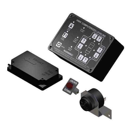
SERVICE MANUAL
HWH TOUCH PANEL-CONTROLLED
R
725 SERIES HYDRAULIC LEVELING SYSTEM
Single Step Touch Panel Leveling Control
Ph: 800/321-3494 (or) 563/724-3396 | Fax: 563/724-3408
H H
W
CORPORATION
FEATURING:
BI-AXIS Hydraulic Leveling
R
Straight-Acting Jacks
(Without Dump)
(With Dump)
(With Pilot Dump)
R
EXCESS
SLOPE
EXTEND
AUTO
LEVEL
NOT IN
PARK/
BRAKE
AUTO
MANUAL
STORE
DUMP
RETRACT
TRAVEL
MODE
CANCEL
WARNING!
UNDERSTAND OPERATOR'S MANUAL BEFORE USING. BLOCK FRAME AND TIRES
SECURELY BEFORE REMOVING TIRES OR CRAWLING UNDER VEHICLE.
HWH CORPORATION
(On I-80, Exit 267 South)
2096 Moscow Road | Moscow, Iowa 52760
www.hwh.com
R
EXTEND
MANUAL
RETRACT
ML48380/MI91.0030
19MAR12
Advertisement
Table of Contents
Troubleshooting

Related Manuals for HWH 725 Series


Summary of Contents for HWH 725 Series
- Page 1 CORPORATION SERVICE MANUAL HWH TOUCH PANEL-CONTROLLED 725 SERIES HYDRAULIC LEVELING SYSTEM FEATURING: Single Step Touch Panel Leveling Control BI-AXIS Hydraulic Leveling Straight-Acting Jacks (Without Dump) (With Dump) (With Pilot Dump) HWH COMPUTERIZED LEVELING EXCESS SLOPE EXTEND EXTEND AUTO LEVEL NOT IN...
- Page 2 This Repair Manual is offered as a guide only. It is impossible to anticipate every problem or combination of problems. For any problems encountered that are not addressed in this manual, contact HWH Corporation for assistance. (800-321-3494) PROCEED WITH SYSTEM OPERATION MI91.1132...
-
Page 3: Trouble Shooting
3. Check that the oil reservoir is full with the jacks in the fully grounded before applying power to the system. retracted position. If the vehicle is equipped with HWH room extensions, refer to the HWH Owners Manual for proper Tightening of hose ends: If tightening a new hose end, position of the room when checking the oil level. - Page 4 CONTROL IDENTIFICATION 725 SERIES LEVELING SYSTEM COMPUTER-CONTROL "MANUAL DUMP" "EXCESS SLOPE" LOWER FRONT Button Indicator light AUTO LEVEL Manual button Indicator light RAISE FRONT Manual button "AUTO LEVEL" Button HWH COMPUTERIZED LEVELING JACK DOWN "NOT IN PARK" Indicator light EXCESS...
-
Page 5: System Operation
For manual leveling, the HWH touch panel has a "DUMP" button. The "DUMP" button will work if the ignition is on and the park brake is set. If the vehicle uses the HWH air dump valves, the "DUMP" button must be pushed and held until all of the air is exhausted from the vehicle suspension system. - Page 6 725 TROUBLE SHOOTING GUIDE AUTOMATIC OPERATIONS CONTINUED. . . STABILIZING: Each jack has a pressure switch. When the jack pressure switch is on, the computer knows that jack is on the ground. Because of possible thermal contraction, it is important that all jacks have lifted the vehicle at least 3/4 of an inch. This switch can be adjusted.
- Page 7 725 TROUBLE SHOOTING GUIDE STORE MODE The touch panel has a "STORE" button and light. The ignition must be in the "ON" or "ACC." position. The STORE light will come on when the "STORE" button is pushed. The front jacks will retract for five (5) seconds before the rear jacks start to retract.
- Page 8 When voltage issues are addressed, it is important to check chassis grounds, positive voltage connections and battery condition to ensure a good DC voltage circuit for the vehicle. Problems with these items, especially the chassis grounds, will create voltage issues for the HWH equipment.
- Page 9 SEE: MP84.3240 MP84.3240 2. The pump led is on. NOTE: If the vehicle is equipped with HWH rooms, unplug the pump request wire coming from the 32 pin I/O module connector. If now the pump does not run, the problem is with the room controls or wiring. Contact HWH Corporation for assistance.
- Page 10 I/O module and unplug the touch panel. At the 32 pin connector, check that pin B1 (6800 wire) and ELECTRICAL CONNECTION DIAGRAM 725 SERIES SINGLE STEP LEVELING SYSTEM PARK BRAKE - MASTER WARNING LIGHT AND BUZZER D1 (6120 wire) have no continuity to any other pin in the connector or to ground. Repair as necessary.
- Page 11 If only one LED or no LEDs are on, unplug the sensing unit from the harness. SEE: MP84.3430 SEE ELECTRICAL CONNECTION DIAGRAM - 725 SERIES SINGLE STEP LEVELING SYSTEM YELLOW LEDS 1. The yellow level indicator lights on the touch panel all go out.
- Page 12 8100 NOTE: DIODE ARRANGEMENT MAY NOT BE 8101 PRESENT ON ALL INSTALLATIONS FUSE or the connection of the HWH 9000 wire to the park brake switch. 15 AMP 6120 - TO +12V ACC. SEE ELECTRICAL CONNECTION DIAGRAM MULTIPLEXED INPUT/OUTPUT MODULE...
- Page 13 PART 6. FOR VEHICLES EQUIPPED WITH AIR SUSPENSION The two types of suspension air dump, pilot air dump or HWH air dump valves, are explained in the SYSTEM OPERATION and GLOSSARY sections of this manual. The ignition must be in the "ON" or "ACC"...
- Page 14 WHEN THE "DUMP" BUTTON IS RELEASED. Make sure the vehicle has a pilot air dump system and PUMP RELAY DUMP not a dump system that uses HWH air dump valves. Check the travel LED on the I/O module. If it is on TRAVEL MASTER RELAY after releasing the DUMP button, replace the I/O module.
- Page 15 There is only one output for all the HWH dump valves from the I/O board. If not all of the valves are dumping air, there is a problem with the wiring harness to the valve(s) not working or a problem with the valve(s).
- Page 16 LED while pushing the DUMP button. If the LED is still off, the problem is most likely the I/O module but could be the touch panel. If the LED is now on, there is a short in the harness to the HWH dump valves or one or more HWH air dump valves are bad.
- Page 17 The ignition must be on (or in ACC.) with the park brake set for the pump relay to function. ELECTRICAL CONNECTION DIAGRAM 725 SERIES SINGLE STEP LEVELING SYSTEM PUSH AND HOLD AN UP ARROW. The pump should run and the appropriate jacks should extend. The...
- Page 18 SHOWN HERE BENEATH THE ON PUMP (6230) DEUTSCH CONNECTOR SEE ELECTRICAL CONNECTION DIAGRAM - 725 SERIES If everything with the wire and connection is ok and there is no voltage on the wire with the master SINGLE STEP LEVELING SYSTEM...
- Page 19 ELECTRICAL CONNECTION DIAGRAM LEVELING SYSTEM HYDRAULIC MANIFOLD PUMP AND MASTER RELAYS leaks. If the vehicle is equipped with HWH room extension mechanisms, make sure none of the rooms 50 LB 8101 PRESSURE...
- Page 20 (WITH 4 STRAIGHT-ACTING JACKS) MANIFOLDS MAY HAVE FOUR (4) LARGE VALVES OR FOUR (4) SMALL VALVES should contact HWH Corporation to discuss possible issues that could cause all 4 valves to be bad. NOTE: BEFORE OPERATING MANUAL VALVE RELEASE, READ AND UNDERSTAND PROCEDURE FOR MANUAL JACK RETRACTION IN OPERATOR’S INSTRUCTIONS.
- Page 21 When the contacts close, this completes a ground circuit for the warning light. ELECTRICAL CONNECTION DIAGRAM 725 SERIES SINGLE STEP LEVELING SYSTEM PARK BRAKE - MASTER WARNING LIGHT AND BUZZER TOUCH PANEL - JACK WARNING LIGHTS AND PRESSURE SWITCHES...
- Page 22 If voltage is present, the device MASTER LIGHT/BUZZER CONNECTION DIAGRAM 725 SERIES LEVELING SYSTEM A MASTER WARNING INDICATOR SHOULD ALWAYS BE USED. WHEN THE LEVELING SYSTEM HAS is bad. If voltage is not present, the problem is in the wiring or connections to the device.
- Page 23 WITH VELOCITY SWITCH VALVES Contact HWH Technical Service for assistance. If the jack does not retract, reconnect the hose at 3000PSI PRESSURE SWITCH...
- Page 24 After a brief moment, reinstall the check valve and cap. It should now be possible to retract the jacks with the "STORE" button. If the jacks will still not retract, contact HWH Technical Service for assistance. SEE: MP64.3917 MI91.327Q...
- Page 25 CHECK OUTER CHECK HWH for assistance if a velocity valve problem is suspected. With the solenoid valve closed, remove the valve tube. PRESSURE VALVES (4) HERE ALTERNATE...
- Page 26 BELOW MI15.4571. If the sensing unit cannot be adjusted, proceed to Section B. SEE ELECTRICAL CONNECTION DIAGRAM - 725 SERIES SINGLE STEP LEVELING SYSTEM B. ONE OR MORE YELLOW LEVEL LIGHTS WILL NOT COME ON, NOT GO OUT OR OPPOSING YELLOW LEDS LEVEL LIGHTS ARE LIT.
- Page 27 BELOW It is important to understand the difference between the LEVELING MODE and the STABILIZING SEE ELECTRICAL CONNECTION DIAGRAM - 725 SERIES SINGLE STEP LEVELING SYSTEM MODE. Symptoms that may be similar during the LEVELING and STABILIZING modes may be different YELLOW LEDS problems and require different diagnostics.
- Page 28 Note: If there are no yellow level lights lit on the touch panel, the system will go directly to the stabilize mode of the automatic leveling sequence. If the vehicle has an air suspension with a HWH controlled air dump, the system will dump air for approximately 25 seconds and then proceed to the stabilize mode.
- Page 29 Fix the wire as necessary. If the wire is OK. ELECTRICAL CONNECTION DIAGRAM 725 SERIES SINGLE STEP LEVELING SYSTEM replace the I/O module. SEE MP84.3130 PARK BRAKE - MASTER WARNING LIGHT AND BUZZER...
- Page 30 If the "EXCESS SLOPE" light 6. Clean and check for any leakage at the relief valve. If there is leakage, contact HWH Corporation technical service. does not come on, the 8100 wire or the I/O module is bad. SEE MP84.3240...
- Page 31 G. THE TRAVEL MODE LIGHT WILL NOT COME ON. ALL RED WARNING LIGHTS ARE OUT. The touch panel is most likely the problem but recheck PART 4. Section B. to confirm this. H. FOR VEHICLES WITH AIR SUSPENSIONS AND HWH CONTROLLED AIR DUMP. THE VEHICLE WILL NOT RETURN TO RIDE HEIGHT. Review PART 6.
- Page 32 INSTRUCTION SHEET SENSING UNIT MAINTENANCE/SERVICE REMOTE MOUNTED "POTTED" ELECTRONIC SENSING UNIT SENSING UNIT ACCURACY TOLERANCE The sensing unit has an accuracy tolerance of ± 5.4 inches front to rear and ± 1 inch side to side on a 36 foot vehicle. Typical leveling results will be better. SENSING UNIT ADJUSTMENT / WITH ADJUSTING ENHANCEMENT Level the vehicle by placing a bubble level in the center of the Move the vehicle to an unlevel position and level the...
- Page 33 HYDRAULIC LINE CONNECTION DIAGRAM 625/725 SERIES LEVELING SYSTEM (WITH 4 STRAIGHT-ACTING JACKS) MANIFOLDS MAY HAVE FOUR (4) LARGE VALVES OR FOUR (4) SMALL VALVES NOTE: BEFORE OPERATING MANUAL VALVE RELEASE, READ AND UNDERSTAND PROCEDURE FOR MANUAL JACK RETRACTION IN OPERATOR’S INSTRUCTIONS. VALVES MAY BE EQUIPPED WITH VALVE RELEASE NUTS OR RELEASE CAMS.
- Page 34 HYDRAULIC SCHEMATIC DIAGRAM BI-AXIS LEVELING WITH STRAIGHT-ACTING JACKS 625, 625S OR 725 SERIES NOTE: 50 PSI PRESSURE SWITCH RELIEF VALVE MAY NOT BE USED ON ALL 625 MANIFOLDS. 3500 P.S.I. HYDRAULIC ROOM EXTENSION POWER UNIT MANIFOLD LOCATED HERE WHEN APPLICABLE...
- Page 35 3600psi. There may be a small amount of leakage at the relief valve while adjusting the pump pressure. 5. Tighten the relief valve jam nut and recheck the pump pressure. Readjust if necessary. 6. Clean and check for any leakage at the relief valve. If there is leakage, contact HWH Corporation technical service. ATTACH...
- Page 36 ELECTRICAL CONNECTION DIAGRAM 725 SERIES SINGLE STEP LEVELING SYSTEM PARK BRAKE - MASTER WARNING LIGHT AND BUZZER TOUCH PANEL - JACK WARNING LIGHTS AND PRESSURE SWITCHES PRESSURE PRESSURE SWITCH SWITCH WARNING WARNING SWITCH SWITCH 6235 2000 1000 6235 1200 2200...
- Page 37 ELECTRICAL CONNECTION DIAGRAM 725 SERIES SINGLE STEP LEVELING SYSTEM PARK BRAKE - MASTER WARNING LIGHT AND BUZZER TOUCH PANEL - JACK WARNING LIGHTS AND PRESSURE SWITCHES PRESSURE PRESSURE SWITCH SWITCH WARNING WARNING SWITCH SWITCH 6235 2000 1000 6235 1200 2200...
- Page 38 ELECTRICAL CONNECTION DIAGRAM MULTIPLEXED INPUT/OUTPUT MODULE LED AND WIRE/CONNECTION INFORMATION NOTE: DUMP AND TRAVEL LEDS PRESENT RIGHT REAR JACK BUT NOT ALWAYS USED RIGHT FRONT JACK LEFT FRONT JACK LEFT REAR JACK LINK LIGHT GROUND STUD PUMP RELAY DUMP TRAVEL MASTER RELAY A LIT RED LED INDICATES THERE SHOULD BE +12 VOLTS ON THE CORRESPONDING WIRE.
- Page 39 RELAY (A) GROUND STUD IN MANIFOLD SHOWN HERE BENEATH THE TO GROUND STUD DEUTSCH CONNECTOR ON PUMP (6230) SEE ELECTRICAL CONNECTION DIAGRAM - 725 SERIES SINGLE STEP LEVELING SYSTEM LF RF DETAIL (A) - TOP VIEW MULTIPLEX I/O MODULE FUSE...
- Page 40 DEUTSCH CONNECTOR ON PUMP (6230) TOUCH PANEL HARNESS DETAIL (A) - TOP VIEW SEE ELECTRICAL CONNECTION MULTIPLEX I/O MODULE DIAGRAM - 725 SERIES SINGLE STEP LEVELING FUSE SYSTEM - PILOT AIR DUMP 40 AMP GND 6231 DUMP 9300 TRAVEL 9301...
- Page 41 ELECTRICAL CONNECTION DIAGRAM 725 LEVELING SYSTEM TOUCH PANEL CONNECTIONS HWH COMPUTERIZED LEVELING EXCESS SLOPE EXTEND EXTEND AUTO LEVEL NOT IN MANUAL PARK/ BRAKE AUTO MANUAL STORE DUMP RETRACT RETRACT TRAVEL MODE CANCEL WARNING! UNDERSTAND OPERATOR’S MANUAL BEFORE USING. BLOCK FRAME AND TIRES SECURELY BEFORE REMOVING TIRES OR CRAWLING UNDER VEHICLE.
- Page 42 ELECTRICAL CONNECTION DIAGRAM LEVEL SENSING UNIT SEE WIRE LEGEND 1 2 3 BELOW SEE ELECTRICAL CONNECTION DIAGRAM - 725 SERIES SINGLE STEP LEVELING SYSTEM YELLOW LEDS MOUNTING / ADJUSTMENT ELECTRICAL SCREWS (3) CONNECTION DIAGRAM MULTIPLEXED INPUT/ OUTPUT MODULE BOTTOM VIEW OF...
- Page 43 ELECTRICAL CONNECTION DIAGRAM VOLTAGE TEST INFORMATION TOUCH PANEL IMPORTANT VOLTAGE CHECK POINTS WIRE SOCKET WIRE 5 PIN MTA CONNECTOR PIN 4 RESISTANCE POINTS PIN 1 PIN 5 RELAY TERMINAL (ANY RING TERMINAL CONNECTION) WIRE WHITE 6230 RED 6800 +12 VOLT GROUND +12 ACC STAR WASHER...
- Page 44 ADJUSTMENT FOR JACK PRESSURE SWITCHES ADJUSTMENT FOR JACK PRESSURE SWITCHES The 725 System utilizes a pressure switch on each jack to achieve the proper stabilizing pressure. Each jack should lift the coach 1/2" to 1" when stabilizing the coach. The coach should be leveled in several different positions so that each jack can be checked.
- Page 45 MASTER LIGHT/BUZZER CONNECTION DIAGRAM 725 SERIES LEVELING SYSTEM A MASTER WARNING INDICATOR SHOULD ALWAYS BE USED. WHEN THE LEVELING SYSTEM HAS STRAIGHT-ACTING JACKS A WARNING BUZZER MUST BE USED. NOTE: BY SUPPLYING IGNITION POWER TO THE WARNING BUZZER AND LIGHT, AND "ACC" POWER TO THE TOUCH PANEL, THE SYSTEM MAY BE OPERATED IN ACCESSORY WITHOUT THE BUZZER SOUNDING.
- Page 46 Valve size and voltage are still factors to be valve. Pushing the cam in the considered when replacing any HWH hydraulic wrong direction could damage solenoid valve. Replace a small style 12 volt the valve.
- Page 47 Normally the complete harness for this system is supplied by HWH. There are two wires to each valve, a white wire and a black number 9300 wire. The HWH I/O module switches +12 volts to open the air dump valves.
- Page 48 NOTE: All hydraulic pressure switches supplied by HWH at this time are manufactured be HWH. These switches all look the same. The switches can be identified by a tag near the Packard connector on the switch wire.
- Page 49 This may require a separate ground cable, minimum size #2, to supply the necessary ground for the assembly. The oil level in the pump reservoir should be checked with all HWH cylinders, leveling jacks and/or slides retracted. The oil level should be (1) inch down from the top of the reservoir fill hole.
- Page 50 HWH. TOUCH PANEL: The touch panel supplies operational information to the I/O module. HWH COMPUTERIZED LEVELING The touch panel receives information from the I/O module to turn touch panel indicator lights EXCESS SLOPE on.
Need help?
Do you have a question about the 725 Series and is the answer not in the manual?
Questions and answers
RF jack does not extend automatically but will extend manually
The HWH 725 Series RF jack does not extend automatically because the system detects an "Excess Slope" condition. This happens when two jacks reach full extension, but one or more yellow level lights remain on. When this occurs, the 3000# pressure switch on the manifold closes, sending a ground signal to the I/O module. This causes the pump to shut off, preventing the system from stabilizing and keeping the "Excess Slope" light on. However, the jack can still be extended manually if needed.
This answer is automatically generated
What is the reset button sequence on the HWH 725 series leveling system