
Related Manuals for Kobold KEC-2


Summary of Contents for Kobold KEC-2
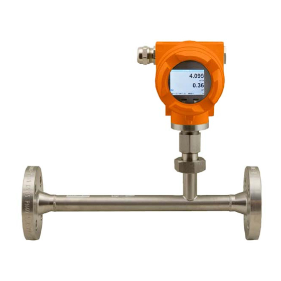
- Page 1 Operating Instructions Thermal Mass Flowmeter for gases Model: KEC-2/KEC-4 KEC-2/KEC-4 K10/0124 Page 1 of 43...
-
Page 2: Foreword
Foreword Dear customer, thank you very much for deciding in favour of the KEC-2/KEC-4. Please read this installation and operation manual carefully before mounting and initiating the device and follow our advice. A riskless operation and a correct functioning of the... -
Page 3: Table Of Contents
6.1.2.2 Passive ........................8 6.1.2.3 Pulse ........................... 8 6.1.2.4 Alarm .......................... 8 Measuring range flow KEC-2/KEC-4 ..................9 6.2.1 Measuring range end values “Low Speed” ................ 9 6.2.2 Measuring range end values “Standard Version” ............10 6.2.3 Measuring range end values “Max Speed Version” ............11 6.2.4... - Page 4 Pulse output ......................33 10.3.4 User Setup ........................34 10.3.5 Advanced ......................... 35 10.3.6 4 -20mA ........................... 36 10.3.7 KEC-2/KEC-4 Info ......................38 Disposal ........................39 EU Declaration of Conformance ................40 UK Declaration of Conformity ..................42 KEC-2/KEC-4 K10/0124 Page 4 of 43...
-
Page 5: Pictograms And Symbols
As a consequence of incorrect handling: possible personal injury or damage Note! Possible hazard As a consequence of incorrect handling: possible personal injury or damage Important! Additional notes, information, tips As a consequence of incorrect handling: Disadvantages in operation and maintenance, no danger KEC-2/KEC-4 K10/0124 Page 5 of 43... -
Page 6: Safety Instructions
By exceeding or falling short of limits there is a risk for people and material, in addition there may occur further functional and operational disturbances. Measures: • Make sure that the KEC-2/KEC-4operates only within the permissible and listed limits on the nameplate • Ensure the operation within the performance data of KEC-2/KEC-4in connection with the application •... -
Page 7: Intended Use
• If carrying out welding work on the pipeline the grounding of the welding unit is not allowed to be done over the KEC-2/KEC-4itself. • The installer has to ensure that the KEC-2/KEC-4is connected according to the electrical connection diagrams properly. The sensor must be grounded, unless special protective measures have been taken (e.g. -
Page 8: Technical Information
KEC-2/KEC-4 Technical Information Operating instructions, data sheet, approvals and further information via the QR code on the device or via www.kobold.com Order Codes Operating instructions, data sheet, approvals and further information via the QR code on the device or via www.kobold.com... -
Page 9: Measuring Range Flow Kec-2/Kec-4
KEC-2/KEC-4 6.2 Measuring range flow KEC-2/KEC-4 6.2.1 Measuring range end values “Low Speed” KEC-2/KEC-4 K10/0124 Page 9 of 43... -
Page 10: Measuring Range End Values "Standard Version
KEC-2/KEC-4 6.2.2 Measuring range end values “Standard Version” KEC-2/KEC-4 K10/0124 Page 10 of 43... -
Page 11: Measuring Range End Values "Max Speed Version
KEC-2/KEC-4 6.2.3 Measuring range end values “Max Speed Version” KEC-2/KEC-4 K10/0124 Page 11 of 43... -
Page 12: Measuring Range End Values "High-Speed Version
KEC-2/KEC-4 6.2.4 Measuring range end values “High-Speed Version” KEC-2/KEC-4 K10/0124 Page 12 of 43... -
Page 13: Dimensions
KEC-2/KEC-4 Dimensions 7.1 Dimension KEC-2/KEC-4 Thread-version KEC-2/KEC-4 thread version Outer Inner Connect pipe pipe dia. dia. [mm] [mm] [mm] [mm] [mm] thread [mm] [mm] 1/2“ 21.3 16.1 176.4 165.7 3/4“ 26.9 21.7 179.2 165.7 1“ 33.7 27.3 182.6 165.7 1 1/4“... -
Page 14: Dimension Kec-2/Kec-4Flanged-Version
KEC-2/KEC-4 7.2 Dimension KEC-2/KEC-4Flanged-version KEC-2/KEC-4 K10/0124 Page 14 of 43... -
Page 15: Installation
35 x D 5 x D 3-dimensional Control valve 45 x D 5 x D 15 x D 5 x D 15 x D 5 x D 15 x D 15 x D 5 x D KEC-2/KEC-4 K10/0124 Page 15 of 43... - Page 16 5 x D The values represent the min.lenghts. In case the min. inlet / outlet runs could not be ensured, it must be expected to get increased or significant d eviations of the measurement values. KEC-2/KEC-4 K10/0124 Page 16 of 43...
-
Page 17: Installation Of Kec-2/Kec-4
The sensor KEC-2/KEC-4 is pre-supplied with the measuring section. 8.3 Alignment Display (Housing) The sensor housing KEC-2/KEC-4 can be turned in both directions, max. 345 °. For this purpose, the housing-connecting nut must be opened. The housing can be rotated to the desired position, a bigger rotaion angle is prevented by internal stop pins. -
Page 18: Connection Diagram
9.1 Cable glands - clamping ranges For ensuring the tightness and strain relief, connector cables with the following diameters must be used. KEC-2/KEC-4 Standard clamping range : Ø 5-9 mm 9.2 Connector pin assignment Version with option board 2x analogue outputs galvanically isolated... - Page 19 Pulse / Alarm * Direction input I- Active** I+ Active ** I- Active ** I+ Active ** * Outputs are galvanically isolated. ** The Current outputs, X5 and X6, are optional.(Active and passive version available). KEC-2/KEC-4 K10/0124 Page 19 of 43...
-
Page 20: Wire Connection
If the sensor placed at the end oft he Modbus system a termination is required. Therfore the enclosed 120R resistor ist o be connected at Pin 1 and Pin 3 of connector „X2“ 9.3.4 Pulse Output KEC-2/KEC-4 K10/0124 Page 20 of 43... -
Page 21: Operation Kec-2/Kec-4
KEC-2/KEC-4 10 Operation KEC-2/KEC-4 The operation of the KEC-2/KEC-4are carried out by 2 optical keys through the glass cover Thus, the KEC-2/KEC-4can be operated from the outside without opening the cap. Optical keys Selection of the individual menu items is done by pressing the ">" and confirm by pressing "OK". -
Page 22: Main Menu
The settings menu could accessed by pressing the key „OK“. But the access to the settings menu is password protected. Factory settings for password at the time of delivery: 0000 (4 times zero). If required the password could be changed at Setup–User setup-Password. KEC-2/KEC-4 K10/0124 Page 22 of 43... -
Page 23: Sensor Setup
For changes, first select the menu item with key „ “ and then confirm it with “OK“. 10.3.1.1 Input / change tube diameter For KEC-2/KEC-4 not adjustable (suspended) as voted on included measuring section with corresponding pipe diameter. KEC-2/KEC-4 K10/0124 Page 23 of 43... -
Page 24: Input / Change Consumption Counter
In case the quantity of units selectable are not presentable on one page, pleas move to next page by pressing „<<“ Confirm selection by pressing 2x „OK“. Procedure for all 4 measurement-variables is analogous. KEC-2/KEC-4 K10/0124 Page 24 of 43... -
Page 25: Definition Of The Reference Conditions
Do not enter the operation pressure or the operation temperature under reference conditions! Setup Sensor Setup Advanced To make changes, first select a menu with button „“ and confirm selection by pressing „OK“ KEC-2/KEC-4 K10/0124 Page 25 of 43... - Page 26 Input values of 0 -10000 in [ms] are possible Setup Sensor Setup Advanced AV-Time The time period for averaging can be entered here. Input values of -1440 1 [minutes] are possible. For average values see display window 3 + 4 KEC-2/KEC-4 K10/0124 Page 26 of 43...
-
Page 27: Setting Of Zeropoint And Low-Flow Cut Off
„OK“. By pressing „“ the position value is incremented by 1. Confirm the input with „OK“ and activate next number position. Leave menu with button „Back“ KEC-2/KEC-4 K10/0124 Page 27 of 43... - Page 28 Setup Sensor Setup ZP Adjust t Reset By selection of „Reset“ all settings for „ZeroPnt“ and. „CutOff“ are reset. 1,03 Menu item to be select with button „“ confirm the reset with „OK“ Leave menu with button „Back“ KEC-2/KEC-4 K10/0124 Page 28 of 43...
-
Page 29: Modbus Setup
KEC-2/KEC-4 10.3.2 Modbus Setup The Flow sensors KEC-2/KEC-4comes with a Modbus RTU Interface. Before commissioning the sensor the communication parameters • Modbus ID, Baudrate, Parity und Stop bit must be set in order to ensure the communication with the Modbus master. -
Page 30: Modbus Settings (2001
1 = even 2 = odd Number of 0 = 1 Stop Bit 2004 2003 UInt16 Stopbits 1 = 2 Stop Bit 0xABCD = Big Endian 2005 2004 UInt16 Word Order 0xABCD 0xCDAB = Middle Endian KEC-2/KEC-4 K10/0124 Page 30 of 43... -
Page 31: Values Register (1001
Float Flow in cfm 1189 1188 Float Flow in Ncfm 1197 1196 Float Flow in kg/h 1205 1204 Float Flow in kg/min 1213 1212 Float Flow in kg/s 1221 1220 Float Flow in kW KEC-2/KEC-4 K10/0124 Page 31 of 43... -
Page 32: Remark
GasTemp °C 1419 1418 Float GasTemp °F 1427 1426 Float Remark: For more additional Modbus values please refer to the separate Operating Instructions Modbus KEC-2/KEC-4 Installation and Operating Instructions for the sensors KEC-1 and KEC-2/KEC-4 K10/0124 Page 32 of 43... -
Page 33: Pulse /Alarm
180000 3000 3000000 Table 1 Maximum flow for pulse output Entering pulse values that are not allow a presentation to the full scale value, are not allowed. Entries are discarded and error message displayed. KEC-2/KEC-4 K10/0124 Page 33 of 43... -
Page 34: Usersetup
180°. Currently 4 languages have been implemented and could be selected with button „“ Change of language by confirming with “OK”. Leaving the menu with button “back”. KEC-2/KEC-4 K10/0124 Page 34 of 43... -
Page 35: Advanced
KEC-2/KEC-4 10.3.5 Advanced Settings Advanced By pressing „Factory Reset“ the sensor is set back to the factory settings. KEC-2/KEC-4 K10/0124 Page 35 of 43... -
Page 36: -20Ma
For saving the changes done press button „Save“ discard the changes press button “Cancel”. Leaving the menu with „Back“. 0.000 m³/h 1098.9 m³/h 169,8 m/s 1098.9 m³/h KEC-2/KEC-4 K10/0124 Page 36 of 43... - Page 37 To make changes first select a menu item "Current Error" with button „“ and then select by pressing the „OK“ desired mode For saving the changes done press button „Save“ discard the changes press button “Cancel”. Leaving the menu with „Back“. KEC-2/KEC-4 K10/0124 Page 37 of 43...
-
Page 38: Kec-2/Kec-4 Info
KEC-2/KEC-4 10.3.7 KEC-2/KEC-4 Info Setup Sensor Setup Info Here you get a brief description of the sensor data incl. the calibration data. 92,7 m/s 600m³/h Under Details, you are able to see in addition the Run Time: 2d 21h 23m 12s calibration conditions. -
Page 39: Disposal
(Cd, Hg, Li or Pb) of the heavy metal that is decisive for the classification as containing pollutants: 1. „Cd" stands for cadmium 2. „Hg" stands for mercury 3. „Pb" stands for lead 4. „Li" stands for lithium Electrical and electronic equipment KEC-2/KEC-4 K10/0124 Page 39 of 43... -
Page 40: Eu Declaration Of Conformance
EN IEC 63000:2018 Technical documentation for the assessment of electrical and electronic products with respect to the restriction of hazardous substances Additionally for KEC-2/KEC-4 with nominal size: DN32-DN50 and nominal pressure: PN16, as well as with nominal size DN32-DN80 and nominal pressure:... - Page 41 PN designated - Part 1: Steel flanges DIN EN ISO 17637 Non-destructive testing of welds - Visual testing of fusion- welded joints Hofheim, 30 Jan. 2024 H. Volz J. Burke General Manager Compliance Manager KEC-2/KEC-4 K10/0124 Page 41 of 43...
-
Page 42: Declaration Of Conformity
Technical documentation for the assessment of electrical and electronic products with respect to the restriction of hazardous substances. Additionally for KEC-2 with nominal size: DN32-DN50 and nominal pressure: PN16, as well as with nominal size DN32-DN80 and nominal pressure: PN40: BS EN ISO 5817:2014 –... - Page 43 PN designated. Steel flanges BS EN ISO 17637 Non-destructive testing of welds. Visual testing of fusion- welded joints Hofheim, 30 Jan. 2024 H. Volz J. Burke General Manager Compliance Manager KEC-2/KEC-4 K10/0124 Page 43 of 43...
Need help?
Do you have a question about the KEC-2 and is the answer not in the manual?
Questions and answers