
Related Manuals for Wohler DC 410FLOW


Summary of Contents for Wohler DC 410FLOW
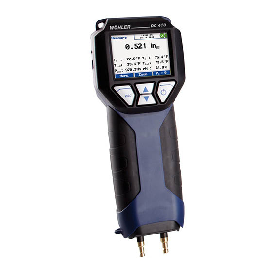
- Page 1 99 Washington Street Melrose, MA 02176 Phone 781-665-1400 Toll Free 1-800-517-8431 Visit us at www.TestEquipmentDepot.com Manual Pressure Differential and Flowmeter FLOW Wöhler DC 410 The Measure of Technology...
-
Page 2: Table Of Contents
Contents Contents General Information ......4 Operation Manual Information ....... 4 Notes ............. 4 Intended Use ..........4 Basic equipment ..........5 Transport ............5 Information on disposal ......... 5 Manufacturer ..........5 Specifications ........6 Measured Data ..........6 Calculated Values ......... - Page 3 Contents 6.3.1 Measuring the Airflow (Pitot) ......26 6.3.2 Grid-point Measurements ......27 Option „Airflow (k value)“ ......30 6.4.1 Theoretical Backround ......... 30 Flow 6.4.2 Connecting the Wöhler DC 410 to the Vent ............. 31 6.4.3 Performing the Test ........32 Option “4 Pa Test“...
-
Page 4: General Information
General Information General Information Operation Manual This operation manual allows you to work safely FLOW with the Wöhler DC 410 . Please keep this Information manual for your information. FLOW The Wöhler DC 410 Flow and Pressure Meter should be employed by professionals for its in- tended use only. -
Page 5: Basic Equipment
General Information Basic equipment Meter Components FLOW Wöhler DC 410 Flow and Pressure Meter 2 capillary tubes Batteries Plastic case Transport ATTENTION! Improper transport can harm the instrument. Always transport the instrument in the provided carrying case in order to prevent damage. The pressure connectors have to be protected by the protection cap. -
Page 6: Specifications
Specifications Specifications Measured Data Differential pressure Description Data Range ±100 hPa Accuracy < 3 % of the reading, if the value is < ± 10 Pa, better than ± 0.3 Pa Resolution 0.1 Pa at -1,100 Pa to +1,100 Pa, otherwise 1 Pa Measurement of very small pressures Description... -
Page 7: Calculated Values
Specifications External temperature probe Description Data (optional, e.g. with Measuring Pli- Range 2 canals, -20.0 °C to ers for Temperature Measurement +800.0 °C or Special Wall Temperature Probe) Accuracy < ± 2 °C at 0°C to 133°C, otherwise 1.5 % of the value, ac- cording to the directive EN 50379-2 Resolution... - Page 8 Specifications Air speed Description Data Range 0.3 m/s to 120 m/s Resolution 0.01 m/s Continuous density automatic, with correction temperature signal...
-
Page 9: Logger
Specifications Logger Description Data Extent 9999 measurements, each with the meas- ured value of pressure and humidity and three temperature values (if the external temperature sensors are connected) can be stored in the internal memory. The user can set the log rate from 1 second to 24 hours. -
Page 10: Technical Data
Specifications Technical Data Description Data Current consumption 4 AA rechargeable batteries or 4 AA disposable batteries 1.5 volt - working mode: ca. 60 mA, - off-mode and log mode: ca. 45 µA for clock and processor Interfaces USB- (COM-Port), data transfer to the PC It is possible to trans- fer the data directly from the meter to the... -
Page 11: Component Explanation
Component Explanation Component Explanation Basic Unit © © © © Fig. 1: Overview... - Page 12 Component Explanation Number Function Mini-USB-Port Connection for protection cap Power jack Color display 5 ESC key context-sensitive Escape NOTE! Keeping this button pressed will always call up the main menu. 6 Arrow keys The function changes according to the context. Scroll up and down.
-
Page 13: Probes And Components
Component Explanation Probes and Components S-tube probe for measuring the air speed (see chapter 6.2) and the airflow (see chapter 6.3). Insert the plug of the S-tube probe into jack 11 FLOW (Fig. 1) of the Wöhler DC 410 ... - Page 14 Component Explanation Two temperature measuring pliers can be con- nected at the same time. Insert the plug of the temperature measuring pliers into the jacks 11 and 12 (Fig. 1) of the FLOW Wöhler DC 410 The temperature value measured by the meter connected to jack 11 will be indicated in the display as T1 and the one measured by the meter con- nected to jack 12 will be shown as T2.
-
Page 15: Function
Component Explanation Function Pressure socket (-) Pressure socket (+) Pressure sensor Absolute-pressure and humidity sen- Fig. 6: Interior structure of the meter... -
Page 16: Functions
Component Explanation FLOW Functions The Flow and Pressure Meter Wöhler DC 410 is a high precision multimeter for the measure- ment of differential pressure, volume flow and temperature as well as the registration of humidity and barometric pressure. Because of its extremely high precision, the meter measures even very small pressures. - Page 17 Component Explanation Fig. 8: Display details The display is divided into a status, a menu and a readings segment. The currently selected task is shown in the left status segment. - Date and time, customer (if selected), system diagnosis status and battery level are shown in the status segment on the right.
-
Page 18: Getting Started
Getting Started Getting Started Check Battery Status When the device is switched on, the battery indi- cation is displayed in the upper right hand corner of the screen. A fully charged set of batteries is shown as a solid green battery symbol. An empty red symbol indicates discharged or empty batter- ies. - Page 19 Getting Started ATTENTION! - Ensure rechargeable batteries are equipped in FLOW the DC 430 before charging. Never try to charge disposable batteries. Use 4 AA rechargeable batteries only. - Only use the Wöhler charger. How to charge the batteries: Before you plug the recharger into the outlet, connect it with the charging connection of the FLOW...
-
Page 20: Operation
Operation Operation Turning the Pressure ATTENTION! Computer on and Self Before the meter is used, a visual check must Check ensure each and every time that all functions work properly. Turning on the meter: Press on/off-key (on the right) The Meter will automatically start with a 10 se- cond self test and zeroing. -
Page 21: Special Tips
Operation Special Tips Holding the left button pressed (ESCAPE) will always stop the current menu and call up the main menu. On/Off Escape Scroll/Zoom Fig. 14: Display and keys In the measuring mode, press the up or down key to enter the zoom-mode. - Page 22 Operation FLOW The Wöhler DC 410 is equipped with integrated magnetic holders on the rear side. The magnetic holders will fix the analyzer on any magnetic material surface. It is also possible to fix the Wöhler DC FLOW with the supporting loop during the measurement.
-
Page 23: Measurement Modes In The Main Menu
Measurement Modes in the Main Menu Measurement Modes in the Main Menu Selecting the Press "menu" to switch to the main menu. In the main menu, all submenus and applications can be Main Menu activated. The following options can be selected: Fig. -
Page 24: Measuring The Air Speed
Measurement Modes in the Main Menu 6.2.1 Measuring the Air Speed Connect the pressure connector of the S-tube to the (+) overpressure socket of the Wöhler Static pressure Temperature FLOW DC 410 Connect the static pressure connector of the S-tube to the (-) underpressure socket of the FLOW Wöhler DC 410 Immersion... -
Page 25: Theoretical Background
Measurement Modes in the Main Menu Press the left key to bring up the menu again. Press the right key to zero the pressure sen- sor. NOTE! The pressure sensor must be zeroed, if the meter does not indicate V=0 after the tubes have been removed. -
Page 26: Option „Airflow (Pitot)
Measurement Modes in the Main Menu Option „Airflow In this menu, the airflow is measured in l/s or in /h. Select the unit in the setup menu. (see (Pitot)“ chapter 6.12) FLOW With the Wöhler DC 410 , a grid point meas- urement can be done, so that the information pro- vided by the measurement is significant (see chapter 6.3.2). -
Page 27: Grid-Point Measurements
Measurement Modes in the Main Menu Press "Stop" and then "Area" to bring up the Entering the cross section cross section area menu. area: Go to the parameter "Profile" with the up and down keys. Use the right arrow to select between "round, rectangle, arbitrary"... - Page 28 Measurement Modes in the Main Menu The readings of the first measurement are shown in the display. Press "Evaluation" to display all the readings. The result of the first measurement will not be shown, because it has not been accepted yet. ...
- Page 29 Measurement Modes in the Main Menu In the display, the average of the speed readings is shown above the readings. The airflow is indicated in the upper part of the display as the average of the results of all meas- urements performed until now.
-
Page 30: Option „Airflow (K Value)
Measurement Modes in the Main Menu Option „Airflow Select the submenu "Airflow (k-value)" to measure the airflow at apertures or similar measuring open- (k value)“ ings of air pipes or vents. This method is simple and precise and therefore suitable for the adjust- ment of air pipe systems and vents. -
Page 31: Connecting The Wöhler Dc 410 To The Vent
Measurement Modes in the Main Menu Flow 6.4.2 Connecting the Wöhler DC 410 to the Vent FLOW Connect the Wöhler DC 410 with two measuring hoses to the vent. FLOW The overpressure socket (+) of the DC 410 has to be connected to the aperture with the higher pressure and the underpressure socket (-) to the aperture with the lower pressure. -
Page 32: Performing The Test
Measurement Modes in the Main Menu 6.4.3 Performing the Test After the measuring mode has been activated, in the upper part of the display the airflow will be indicated in the unit selected in the setup-menu. Underneath, the airflow will be indicated in the other unit. - Page 33 Measurement Modes in the Main Menu Press P = 0 (menu bar, see Fig. 31: Menu "Air- flow (k value)") to zero the pressure sensor. NOTE! We recommend to zero the pressure sensor, if the pressure indicated in the display is not P after the measuring hoses have been removed.
-
Page 34: Option 4 Pa Test
Measurement Modes in the Main Menu “ Option 4 Pa The 4 Pa Pressure Test is a simple control of the underpressure limit 4 Pa for the confirmation of a Test“ sufficient combustion air supply. Capillary In a closed room or in connected rooms, simulta- hose inside neous operation of non-roomsealed heating appli- pressure... - Page 35 Measurement Modes in the Main Menu How to perform the 4 Pa Pressure Test: Switch on appliance and all air conditioning (fan, dryer) with maximum power. Open an outside window or a door to the reference room and test proper operation of the appliance, ensure that there are no back- draft conditions.
- Page 36 Measurement Modes in the Main Menu NOTE! Press "Stop" to stop the 4 PA Test earlier.
- Page 37 Measurement Modes in the Main Menu Normally a diagram as shown in figure Fig. 38. will appear. The pressure peaks in the diagram are caused by the rapid movement of the window or the door and therefore they are not relevant for the interpretation of the diagram.
-
Page 38: Option „Energy Utilization Check
Measurement Modes in the Main Menu Option „Energy The Energy Utilization Check provides a checklist to determine the potential efficiency improve- Utilization ments. Check“ NOTE! It is necessary to connect the S-tube probe (see accessories). Select the supmenu "EUC" from the main menu. In the Display the following options will appear: ... - Page 39 Measurement Modes in the Main Menu Measuring the Ventilation Loss The ventilation loss has to be measured 30 se- conds after burn-out. It is based on the measure- ment of the air speed and of the temperature of the residual core flow. The test fulfills the require- ments of DIN EN 15378, national annex, concern- ing the evaluation of the ventilation loss of boilers.
- Page 40 Measurement Modes in the Main Menu How to perform the measurement: NOTE! Connect the Special Wall Temperature Probe (see accessories) to jack 12, fig. 1. If you do not connect any room temperature probe, the temperature measured by the internal probe will be adopted.
- Page 41 Measurement Modes in the Main Menu NOTE! The S-tube must be adjusted before the meas- urement procedure starts, since it is required to check and/or adjust the oppositely running orien- tation of the measuring tubes after loosening the knurled screws and adjusting the immersion depth.
- Page 42 Measurement Modes in the Main Menu The measured values are converted according to the following formula: Luft außenIST Norm Kessel außenREF Description Data Ventilation loss in % LS_Norm Area cross section of the flue gas pipe in m...
- Page 43 Measurement Modes in the Main Menu After the measurement of the ventilation loss has been completed, "Ventilation loss" will be marked by a tick mark in the "Energy Utilization Check" screen. How to print out a report: Select the 'PRINT' option from the main menu. How to save the results: ...
- Page 44 Measurement Modes in the Main Menu How to measure the surface loss: Enter the nominal power of the burner. Pess "Proceed" Enter the surface temperature T of the single area and its dimensions (width x height). Measure the average surface temperatures with the Special Wall Temperature Probe con- FLOW...
-
Page 45: Option „U Value
Measurement Modes in the Main Menu Option „U value“ The heat transfer coefficient (U value) describes the heat flow W/m²k flowing through a building element. NOTE! A Special Wall Temperature Probe is needed to measure the heat transfer coefficient (see acces- sories). -
Page 46: Option "Volume
Measurement Modes in the Main Menu Option “Volume“ In this submenu, the content of a closed and her- metic room with a volume up to 6000 l is deter- mined (e.g. tank, bottle or pipe). NOTE! For the volume measurement, a syringe (up to 100 ml), a cross piece and connection hoses are needed. - Page 47 Measurement Modes in the Main Menu Pump volume Max. tube volume Guidelines for the selection of the sample volume that has to be 163 ml 80 l drawn with the soot test pump. (1 strike with the soot test pump) 489 ml 240 l (3 strikes with the soot...
-
Page 48: Graph / Record
Measurement Modes in the Main Menu Select "Start measurement" and press "Start". In the display the request to add/remove the sam- ple volume will appear. Take the sample volume with the syringe or the soot test pump. Fig. 54: Presettings (Volume test) ... - Page 49 Measurement Modes in the Main Menu NOTE! Ensure that the meter is connected to the power supply or that the batteries are charged. A graph which presents the measured values appears in the display. Press "Stop" to save the logged data. ...
-
Page 50: Printing Out Measurement Records
Measurement Modes in the Main Menu 6.10 Printing out Mea- In the main menu, select "PRINT" to start a data printout of all measured values. surement Re- First, a print preview will appear on screen. In the cords Setupmenu, the user can select between printing with the Wöhler thermal fast printer TD 600 or another printer. -
Page 51: Option "Save Measurements
Measurement Modes in the Main Menu 6.11 Option "Save To save all records which are marked by a tick mark in the main menu, select the "Save meas- measurements" urement" option. 6.12 Option "SETUP" Select the option "SETUP" to enter the main setup menu. - Page 52 Measurement Modes in the Main Menu urement” is selected in the setup-menu. (Set- up>attenuation>fine pressure measurement.) Default: 75% Temperature unit Select the temperature unit °C or °F. Airflow unit Select between m /h or l/s The airflow value will be indicated in the selected unit in the center of the display and below, smaller, in the other unit.
-
Page 53: Option 'Data Management
Option 'Data management' measurement Printer logo Enter a custom corporate logo (6 lines) that will appear in every printout. FLOW Factory defaults Reset the DC 430 to its factory default setting (except the calibration). Option 'Data management' FLOW When working with the Wöhler DC 410 it is possible to save and manage custom- ized data which can be assigned to different risers. -
Page 54: Save Customer Records
Option 'Data management' 7.1.1 Save Customer Re- When different measurements have been per- formed at one installation, they can be assigned to cords a customer as follows: Select the 'Save measurements' option from the main menu. Use the up- and down keys to navigate through the menu. -
Page 55: Creating A New Customer Folder
Option 'Data management' 7.1.2 Creating a New Cus- tomer Folder The user can create new customer folders or new risers in the customer menu (see Fig. 12) or when saving the data. Enter the name, a customer num- ber and the name of the riser. NOTE! The user can save all together 128 risers in the meter and assign them to different customers. -
Page 56: Option "Data Management
Option 'Data management' Option "Data management" In the "Data management" display, the current number of customer folders and risers is indicat- Select "Print protocol" to print a report of any saved measurement. Select "Delete riser" to delete a single riser. NOTE! When there is only one riser saved in a customer Fig. -
Page 57: Troubleshooting
Troubleshooting Troubleshooting Error message Possible reason Solution Batteries low Disposable or rechargeable Replace or recharge batteries are empty. batteries. ATTENTION! Overpressure high pressure Deflate pressure Maintenance FLOW Proper operation of the Wöhler DC 410 quires regular maintenance. Maintenance Interval Maintenance work work If required (user) Clean the device with a... -
Page 58: Warranty And Service
Warranty and Service Warranty and Service FLOW 10.1 Warranty Each Wöhler DC 410 probe will be tested in all functions and will leave our factory only after extensive quality control testing. The final control will be recorded in detail in a test report and deliv- ered with any unit. -
Page 59: Accessories
Accessories Accessories Probes and sensors Special Wall Temperature Probe Order no. 4651 Measuring pliers for temperature measurement Order no. 6679 S-tube probe Order no. 3343 Accessories Volume Measurement Leakage Test Set Order no. 21580 High pressure cone G 1/2 with sealing rings Order no. -
Page 60: Declaration Of Conformity
Declaration of conformity Declaration of conformity The manufacturer: Wöhler Messgeräte Kehrgeräte GmbH Schützenstr. 41, D-33181 Bad Wünnenberg declares that the product product name: Flow and Pressure Meter FLOW model number: Wöhler DC 410 complies with the following requirements for conformity and electromagnetic compati- bility:: EN 61326-1: 1997+ A1: 1998+A2:2001 DIN EN 61010-1:2002... -
Page 61: Points Of Sale And Service
Test Equipment Depot - 800.517.8431 - 99 Washington Street Melrose, MA 02176 TestEquipmentDepot.com...
Need help?
Do you have a question about the DC 410FLOW and is the answer not in the manual?
Questions and answers