
Subscribe to Our Youtube Channel
Related Manuals for Moxa Technologies NPort Z3150 Series


Summary of Contents for Moxa Technologies NPort Z3150 Series
- Page 1 NPort Z3150 Series User’s Manual Edition 4.0, February 2017 www.moxa.com/product © 2017 Moxa Inc. All rights reserved.
- Page 2 NPort Z3150 Series User’s Manual The software described in this manual is furnished under a license agreement and may be used only in accordance with the terms of that agreement. Copyright Notice © 2015 Moxa Inc. All rights reserved. Trademarks The MOXA logo is a registered trademark of Moxa Inc.
-
Page 3: Table Of Contents
Table of Contents Introduction ............................1-1 Overview ............................1-2 Package Checklist ..........................1-2 Product Features ..........................1-3 Product Specifications ......................... 1-3 Pin Assignments and Cable Wiring ......................1-4 Power Input Pinouts ..........................1-5 Getting Started ..........................2-1 Overview ............................2-2 Panel Layout ............................ - Page 4 Baud Rate ..........................5-14 Data Bits ..........................5-14 Stop Bits ..........................5-14 Parity ............................5-14 Flow Control ..........................5-14 FIFO ............................5-14 Interface ..........................5-15 Operating Settings > Port 1 or 2 ......................5-15 Settings for RealCOM Mode ........................ 5-15 TCP Alive Check Time ........................
- Page 5 Configuring Mapped Serial Ports ....................7-8 NPort Search Utility ........................... 7-12 Installing NPort Search Utility ..................... 7-12 Finding NPort Device Servers on Network ..................7-14 Modifying NPort IP Addresses...................... 7-15 Upgrading NPort Firmware ......................7-16 Linux Real TTY Drivers ........................7-17 Basic Steps ..........................
-
Page 6: Introduction
Introduction The following topics are covered in this chapter: Overview Package Checklist Product Features Product Specifications Pin Assignments and Cable Wiring Power Input Pinouts... -
Page 7: Overview
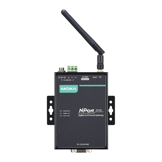
NPort Z3150 Series Introduction Overview The NPort Z3150 is a gateway that provides computers with an Ethernet interface to a ZigBee PAN. Unlike a bridge, which logically extends a PAN across an Internet connection, a gateway provides network services on behalf of a ZigBee PAN. -
Page 8: Product Features
NPort Z3150 Series Introduction Product Features • Instant connection of any Ethernet device to a ZigBee network • RS-232/422/485 port supporting baudrates up to 921.6 Kbps • Web-based configuration over Ethernet • Secure data access with AES • Dual power inputs (1 power jack and 1 terminal block) -
Page 9: Pin Assignments And Cable Wiring
NPort Z3150 Series Introduction Physical Characteristics Housing: Aluminum Weight: 780 g (1.72 lb) Dimensions: Without ears: 77 x 111 x 26 mm (3.33 x 4.37 x 1.02 in) With ears: 100 x 111 x 26 mm (3.94 x 4.37 x 1.02 in) -
Page 10: Power Input Pinouts
NPort Z3150 Series Introduction Power Input Pinouts Shielded DC Power DC Power Ground Input 1 Input 1... -
Page 11: Getting Started
Getting Started The following topics are covered in this chapter: Overview Panel Layout LED Indicators Top Panel LED Indicators End Panel LED Indicators Pull High/Low Resistors for RS-422/485 Function Block Connecting the Hardware ... -
Page 12: Overview
NPort Z3150 Series Getting Started Overview This chapter presents the hardware features of the NPort Z3150 and explains how to connect the hardware. Panel Layout LED Indicators Top Panel LED Indicators There are three LEDs on NPort Z3150. LED Name... -
Page 13: End Panel Led Indicators
NPort Z3150 Series Getting Started End Panel LED Indicators Name Color Function Ethernet Orange 10 Mbps Ethernet connection Green 100 Mbps Ethernet connection Ethernet cable is disconnected or has a short Pull High/Low Resistors for RS-422/485 You may need to set the pull high/low resistors when termination resistors are used for certain RS-422 or RS-485 environments. -
Page 14: Function Block
NPort Z3150 Series Getting Started Function Block Connecting the Hardware ATTENTION Before connecting the hardware, follow these important wiring safety precautions: Disconnect power source Do not install or wire this unit or any attached devices with the power connected. Disconnect the power before installation by removing the power cord before installing and/or wiring your unit. -
Page 15: Connecting To The Network
NPort Z3150 Series Getting Started Connecting to the Network Use the supplied Ethernet cable to connect the NPort to your Ethernet network. If the cable is properly connected, the NPort will indicate a valid connection to the Ethernet as follows: •... -
Page 16: Initial Ip Configuration
Initial IP Configuration The following topics are covered in this chapter: Overview Factory Default IP Settings Using ARP to Assign IP Address Using the Telnet Console to Assign IP Address... -
Page 17: Overview
NPort Z3150 Series Initial IP Configuration Overview This chapter presents several ways to assign the NPort’s IP address for the first time. Please refer to Chapter 2 for instructions on connecting to the network. The web console is the recommended method for configuring the NPort. Please refer to Chapter 5 and 6 for details on using the web console for configuration. -
Page 18: Using The Telnet Console To Assign Ip Address
NPort Z3150 Series Initial IP Configuration Using the Telnet Console to Assign IP Address 1. Select Command Prompt from Accessories 2. Enter telnet 192.168.127.254 (the NPort’s default IP address) and click [OK]. 3. Select 2 to select Network settings and press Enter... - Page 19 NPort Z3150 Series Initial IP Configuration 5. Key in your desired IP address and press Enter 6. Input m to go back main menu and press Enter 7. Input s to save and restart configuration and press Enter 8. Press y to confirm action for save and restart configuration and press Enter. The NPort will reboot with the...
-
Page 20: Introduction To Operation Modes
Introduction to Operation Modes The following topics are covered in this chapter: Overview Real COM Mode TCP Server Mode TCP Client Mode UDP Mode... -
Page 21: Overview
NPort Z3150 Series Introduction to Operation Modes Overview This chapter introduces the different serial port operation modes that are available on the NPort Z3150. Each serial port on the NPort is configured independently of the other ports, with its own serial communication parameters and operation mode. -
Page 22: Tcp Server Mode
NPort Z3150 Series Introduction to Operation Modes TCP Server Mode In TCP Server mode, the NPort serial port is assigned an IP:port address that is unique on your TCP/IP network. It waits for the host computer to establish a connection to the attached serial device. This... -
Page 23: Web Console Configuration
Web Console Configuration The Web Console is the most user-friendly method available to configure NPort Z3150. In this chapter, we introduce the Web Console function groups and function definitions. The following topics are covered in this chapter: Overview Quick Setup ... -
Page 24: Overview
NPort Z3150 Series Web Console Configuration Overview This chapter introduces the NPort Web Console and explains how to configure the basic settings. The NPort can be configured from anywhere on the network through its Web Console. Simply point the browser to the device server’s IP address to open the web console. -
Page 25: Quick Setup
NPort Z3150 Series Web Console Configuration ATTENTION If you have forgotten the password, you can use the reset button to load factory defaults, but this will erase all previous configuration information. The web console will appear as shown below. Settings are presented on pages that are organized by folder. Select the desired folder in the left navigation panel to open that page. - Page 26 NPort Z3150 Series Web Console Configuration In Step 1/3, you must assign a valid IP address to the NPort Z3150 before it will work in your network environment. Your network system administrator should provide you with an IP address and related settings for your network.
-
Page 27: Export/Import
NPort Z3150 Series Web Console Configuration In the Step 3/3, you must specify which operation mode you will use. Review your settings at the Finish Settings page to confirm that they are correct, and then click the Save/Restart button to restart the device with the new settings. -
Page 28: Basic Settings
NPort Z3150 Series Web Console Configuration Basic Settings On the Basic Settings page, you can configure Server name, Server location, Time zone (24-hour), Local time, Time server, and Console Settings. Server Name Default NPZ3150_<serial no.> Options free text (e.g., “Server 1”) Description This is an optional free text field to help you differentiate one device server from another. -
Page 29: Local Time
NPort Z3150 Series Web Console Configuration Local Time Default Options Date (yy:mm:dd), Time (hh:mm:ss) Description The NPort has a built-in real-time clock that allows you to add time information to functions such as the automatic warning e-mail or SNMP trap. This field shows the current time according to the NPort’s built-in real-time clock. -
Page 30: Telnet Console
NPort Z3150 Series Web Console Configuration Telnet Console Default Enable Options Enable or Disable Description The “Disable” option for “Telnet Console” is included for security reasons. In some cases, you may want to disable one or both of these console utilities as an extra precaution to prevent unauthorized users from accessing your NPort Z3150. -
Page 31: Ip Configuration
NPort Z3150 Series Web Console Configuration IP Configuration Default Static Options Static, DHCP, DHCP/BOOTP, BOOTP Description This field determines how the NPort’s IP address will be assigned. Static: IP address, netmask, and gateway are user-defined. DHCP: IP address, netmask, gateway, DNS, and time server are assigned by DHCP server. -
Page 32: Gateway
NPort Z3150 Series Web Console Configuration Gateway Default Options IP address (e.g., “192.168.1.1”) Description This field is for the IP address of the gateway, if applicable. A gateway is a network computer that acts as an entrance to another network. Usually, the computers that control traffic within the network or at the local Internet service provider are gateway nodes. -
Page 33: Contact
NPort Z3150 Series Web Console Configuration Contact Default Options free text, 1 to 39 characters (E.g., Support, 886-89191230 #300) Description The SNMP contact information usually includes an emergency contact name and telephone or pager number. Location Default Options free text, 1 to 39 characters (E.g., Floor 1, office 2) Description Specify the location string for SNMP agents such as NPort Z3150. -
Page 34: Channel
NPort Z3150 Series Web Console Configuration Channel Default Options 11 to 26 Description The 2.4GHz channel. The range is from 11 to 26. Output Power Default Options Supports -20, -16, -12, -8, -4, -1.5, 1, 4.5 dBm Description The output from power side... -
Page 35: Security Settings
NPort Z3150 Series Web Console Configuration Security Settings Encryption/Decryption Default Disable Options Enable or Disable Description AES encryption for Zigbee security AES 128-bits Key Default Options HEX codes, from 0-9 and A-F Description Supply 128-bit AES data encryption. Use the following rule to input the AES key. -
Page 36: Baud Rate
NPort Z3150 Series Web Console Configuration ATTENTION Serial communication settings should match the attached serial device. Check the communication settings in the user’s manual for your serial device. Baud Rate Default 115200 Options 50, 75, 110, 134, 150, 300, 600, 1200, 1800, 2400, 4800, 7200, 9600, 19200, 38400,... -
Page 37: Interface
NPort Z3150 Series Web Console Configuration Interface Default RS-232 Options RS-232, RS-422, RS-485 2-wire, RS-485 4-wire Description This field specifies the type of interface the serial port will use. Operating Settings > Port 1 or 2 Click Operating Settings, located under Main Menu, to display the operating settings for both of NPort Z3150’s serial ports. -
Page 38: Tcp Alive Check Time
NPort Z3150 Series Web Console Configuration TCP Alive Check Time Default 7 min Options 0 to 99 min Description This field specifies how long the NPort will wait for a response to “keep alive” packets before closing the TCP connection. The NPort checks connection status by sending periodic “keep alive”... -
Page 39: Allow Driver Control
NPort Z3150 Series Web Console Configuration Allow Driver Control Default Disable Options Disable, Enable Description This field specifies how the port will proceed if driver control commands are received from multiple hosts that are connected to the port. Disable: Driver control commands will be ignored. -
Page 40: Delimiter Process
NPort Z3150 Series Web Console Configuration Delimiter Process Default Do Nothing Options Do Nothing, Delimiter + 1, Delimiter + 2, Strip Delimiter Description This field specifies how data is packed when delimiter characters are received. This field has no effect if Delimiter 1 is not enabled. -
Page 41: Settings For Tcp Server Mode
NPort Z3150 Series Web Console Configuration Settings for TCP Server Mode When Mode is set to TCP Server on a serial port’s Operation Modes page, you will be able to configure additional settings such as TCP alive check time, Inactivity time, and Max connection. -
Page 42: Max Connection
NPort Z3150 Series Web Console Configuration Max Connection Default Options 1 to 8 Description This field specifies the maximum number of connections that will be accepted by the serial port. 1: Only a single host may open the TCP connection to the serial port. -
Page 43: Packet Length
NPort Z3150 Series Web Console Configuration Packet Length Default Options 0 to 1024 Description This field specifies the maximum amount of data that is allowed to accumulate in the serial port buffer before sending. 0: Packet length is disregarded and data in the buffer will be sent as specified by the delimiter settings or when the buffer is full. -
Page 44: Force Transmit
NPort Z3150 Series Web Console Configuration Force Transmit Default 0 ms Options 0 to 65535 Description This field controls data packing by the amount of time that elapses between bits of data. When using this field, make sure that Inactivity time is disabled or set to a larger value. -
Page 45: Tcp Alive Check Time
NPort Z3150 Series Web Console Configuration TCP Alive Check Time Default 7 min Options 0 to 99 min Description This field specifies how long the NPort will wait for a response to “keep alive” packets before closing the TCP connection. The NPort checks connection status by sending periodic “keep alive”... -
Page 46: Designated Local Port 1 To 4
NPort Z3150 Series Web Console Configuration ATTENTION In TCP Client mode, up to 4 connections can be established between the serial port and TCP hosts. The connection speed or throughput may be low if any one of the four connections is slow, since the one slow connection will slow down the other 3 connections. -
Page 47: Delimiter 1 And 2
NPort Z3150 Series Web Console Configuration Delimiter 1 and 2 Default Disabled Options Disabled, Enabled, 0x00 to 0xFF Description These fields are used to define special delimiter character(s) for data packing. Enable Delimiter 1 to control data packing with a single character; enable both Delimiter 1 and 2 to control data packing with two characters received in sequence. -
Page 48: Settings For Udp Mode
NPort Z3150 Series Web Console Configuration Settings for UDP Mode When Mode is set to UDP on a serial port’s Operation Modes page, you will be able to configure additional settings such as Destination address 1 through 4, Local listen port, and Packet length. -
Page 49: Packet Length
NPort Z3150 Series Web Console Configuration Packet Length Default Options 0 to 1024 Description This field specifies the maximum amount of data that is allowed to accumulate in the serial port buffer before sending. 0: Packet length is disregarded and data in the buffer will be sent as specified by the delimiter settings or when the buffer is full. -
Page 50: Force Transmit
NPort Z3150 Series Web Console Configuration Force Transmit Default 0 ms Options 0 to 65535 Description This field controls data packing by the amount of time that elapses between bits of data. When using this field, make sure that Inactivity time is disabled or set to a larger value. -
Page 51: Accessible Ip Settings
NPort Z3150 Series Web Console Configuration Accessible IP Settings The NPort Z3150 uses an IP address based filtering method to control access to itself. Accessible IP Settings allows you to add or block remote host IP addresses to prevent unauthorized access. -
Page 52: Auto Warning Settings > E-Mail And Snmp Trap > E-Mail Server
NPort Z3150 Series Web Console Configuration Auto Warning Settings > E-mail and SNMP Trap > E-mail server The E-mail Alert page is located under E-mail and SNMP Trap in the Auto Warning Settings folder. This is where you specify how and where e-mail is sent when e-mail is used for automatic notification of system and serial port events. -
Page 53: Auto Warning Settings > Event Settings
NPort Z3150 Series Web Console Configuration Auto Warning Settings > Event Settings The Event Settings page is located under Event Settings in the Auto Warning Settings folder. This is where you specify how the NPort will notify you of system and configuration events. Depending on the event, different options for notification are available, as shown above. -
Page 54: Firmware Upgrade
NPort Z3150 Series Web Console Configuration When the DSR changes, the NPort Z3150 will immediately send an e-mail or send an SNMP trap. Event Description Mail This feature helps the administrator manage how the NPort Z3150 sends e-mail to pre-defined e-mail boxes when the enabled events—such as Cold start, Warm start, Authentication failure,... -
Page 55: Change Password
NPort Z3150 Series Web Console Configuration Change Password The Change Password page is used to change the password, first enter the old password in the Old password field. Leave this blank if the NPort is not currently password-protected. Enter the new password twice, once in the New password field and once in the Retype password. -
Page 56: Save/Restart
NPort Z3150 Series Web Console Configuration The Load Factory Default page is used to recovery default settings. Click [Submit] to reset all settings to the factory defaults. Save/Restart The Save/Restart page is used to save configuration settings and then reboot device. Click [Submit] to save configuration settings into device and then restart the NPort. -
Page 57: Web Console: Monitor
Web Console: Monitor The following topics are covered in this chapter: Overview Monitor Line Monitor Async Monitor Async-Settings Monitor ZigBee Monitor ZigBee-Settings... -
Page 58: Overview
NPort Z3150 Series Web Console: Monitor Overview This chapter explains how to use the Monitor functions on the NPort web console. These functions allow you to monitor many different aspects of operation. Monitor Line The Monitor Line page is used to monitor the current operation mode and host connection status for each port. -
Page 59: Monitor Async-Settings
NPort Z3150 Series Web Console: Monitor Monitor Async-Settings The Monitor Async-Settings page is used to view the current communication settings for the serial port. Monitor ZigBee The ZigBee page is used to view the current status of ZigBee network connection. -
Page 60: Monitor Zigbee-Settings
NPort Z3150 Series Web Console: Monitor Monitor ZigBee-Settings The ZigBee-Settings page is used to view the current status of the NPort Z3150 itself. -
Page 61: Installing And Configuring The Software
Installing and Configuring the Software The following topics are covered in this chapter: Overview NPort Windows Driver Manager Installing NPort Windows Driver Manager Adding Mapped Serial Ports Configuring Mapped Serial Ports NPort Search Utility ... -
Page 62: Overview
NPort Z3150 Series Installing and Configuring the Software Overview This chapter describes how to install and use NPort Windows Driver Manager, NPort Search Utility, and NPort Linux and UNIX drivers. These items are located on the Document & Software CD that is provided with the NPort Z3150. - Page 63 NPort Z3150 Series Installing and Configuring the Software 3. Select a destination directory and click [Next] to proceed. 4. Select a folder for the program shortcuts and click [Next] to proceed.
- Page 64 NPort Z3150 Series Installing and Configuring the Software 5. Verify the installation parameters and click Install to proceed. 6. If you see a warning that the software has not passed Windows Logo testing, click [Continue Anyway] to proceed.
-
Page 65: Adding Mapped Serial Ports
NPort Z3150 Series Installing and Configuring the Software 7. The wizard will begin installing the files. When the files have been installed, click [Finish] to complete the installation. Adding Mapped Serial Ports NPort Windows Driver Manager adds a COM port to your PC that is mapped to an NPort serial port. The destination NPort serial port must be set to Real COM mode. - Page 66 NPort Z3150 Series Installing and Configuring the Software 2. Click [Search] to search the network for NPort device servers. In the list of NPort device servers that are found, select the unit(s) that you will use for COM mapping and click [OK].
- Page 67 NPort Z3150 Series Installing and Configuring the Software 3. NPort Windows Driver Manager will list each available serial port and will automatically assign a new COM port to each one. The new COM port will not be accessible by the host system until it has been activated in NPort Windows Driver Manager.
-
Page 68: Configuring Mapped Serial Ports
NPort Z3150 Series Installing and Configuring the Software Configuring Mapped Serial Ports 1. To modify the settings of a mapped serial port, select the desired port(s) and click [Setting] on the main toolbar. 2. On the Basic Setting tab, select the COM Number that will be assigned to the serial port. If you have selected multiple ports, you can assign COM numbers automatically in sequential order by selecting the “Auto Enumerating”... - Page 69 NPort Z3150 Series Installing and Configuring the Software 3. On the Advanced Setting tab, configure Tx Mode, FIFO, and Fast Flush. Tx Mode: In Hi-Performance mode, the driver immediately issues a “Tx Empty” response to the program after sending data to the NPort. In Classical mode, the driver sends the “Tx Empty” response after confirmation is received from the NPort.
- Page 70 NPort Z3150 Series Installing and Configuring the Software Return error if network is unavailable: If this option is disabled, the driver will not return any error even when a connection cannot be established to the NPort. With this option enabled, calling the Win32 Comm function will result in the error return code “STATUS_NETWORK_UNREACHABLE”...
- Page 71 NPort Z3150 Series Installing and Configuring the Software 5. On the Security tab, select the Enable Data Encryption option to enable data to be encrypted when transmitted over the COM ports. After selecting the encryption option, select the Keep connection option to start encrypting COM port communications immediately without restarting the COM ports.
-
Page 72: Nport Search Utility
NPort Z3150 Series Installing and Configuring the Software NPort Search Utility Installing NPort Search Utility 1. The main installation window will open when you insert the Document & Software CD. Click [INSTALL UTILITY] to proceed. Once the program starts running, click [Yes] to proceed. - Page 73 NPort Z3150 Series Installing and Configuring the Software 4. Indicate if you wish to create a desktop icon and click [Next] to proceed. 5. Verify the installation parameters and click Install to proceed. 7-13...
-
Page 74: Finding Nport Device Servers On Network
NPort Z3150 Series Installing and Configuring the Software 6. The wizard will begin installing the files. After the files have been installed, click [Finish] to complete the installation. Finding NPort Device Servers on Network You can use NPort Search Utility to look up or change the IP address of any NPort device servers on the network. -
Page 75: Modifying Nport Ip Addresses
NPort Z3150 Series Installing and Configuring the Software Modifying NPort IP Addresses 1. Once NPort Search Utility has found NPort device servers on the LAN, you can modify any unit’s IP address. Select the desired NPort in the main window and click [Assign IP] on the main toolbar. This will modify the IP address for the active network connection (LAN or WLAN). -
Page 76: Upgrading Nport Firmware
NPort Z3150 Series Installing and Configuring the Software Upgrading NPort Firmware 1. Once NPort Search Utility has found NPort device servers on the LAN, you can upgrade any unit’s firmware. Right-click the desired NPort in the main window and select Upgrade. -
Page 77: Linux Real Tty Drivers
NPort Z3150 Series Installing and Configuring the Software 4. When the displayed status is “OK”, click [Close] to complete the process. ATTENTION NPort Search Utility supports upgrading the firmware of multiple units simultaneously, if each unit is the same model. Hold down the CTRL to add additional units to your selection; hold down the SHIFT key to select a block of units. -
Page 78: Mapping Tty Ports
NPort Z3150 Series Installing and Configuring the Software 5. Execute tar xvfz npreal2xx.tgz to extract all files into the system. 6. Execute /tmp/moxa/mxinst. (For RedHat AS/ES/WS and Fedora Core1, execute “# /tmp/moxa/mxinst SP1”.) The shell script will install the driver files automatically. -
Page 79: Removing Linux Driver Files
NPort Z3150 Series Installing and Configuring the Software The following actions are performed when executing mxdelsvr: 1. Modify npreal2d.cf. 2. Remove the relevant TTY ports in directory /dev. 3. Restart the driver. If the IP address is not provided in the command line, the program will list the installed servers and total ports on the screen. -
Page 80: Configuring The Unix Driver
NPort Z3150 Series Installing and Configuring the Software Configuring the UNIX Driver Modify the configuration: The configuration used by moxattyd is defined in the text file moxattyd.cf, which is in the same directory. You may use vi or any text editor to modify the file, as follows: ttyp1 192.168.1.1 950... -
Page 81: Snmp Agents With Mib Ii & Rs-232-Like Groups
SNMP Agents with MIB II & RS-232-Like Groups The NPort has built-in SNMP (Simple Network Management Protocol) agent software that supports SNMP Trap, RFC1317 RS-232 like groups and RFC 1213 MIB-II. The following table lists the standard MIB-II groups, as well as the variable implementation for the NPort. -
Page 82: Rfc1213 Mib-Ii Supported Snmp Variables
NPort Z3150 Series SNMP Agents with MIB II & RS-232-Like Groups RFC1213 MIB-II Supported SNMP Variables System MIB SysDescr SysContact SysServices SysObjectID SysName SysUpTime SysLocation Interfaces MIB itNumber ifOperStatus ifOutOctets ifIndex ifLastChange ifOutUcastPkts ifDescr ifInOctets ifOutNUcastPkts ifType ifInUcastPkts ifOutDiscards ifMtu... -
Page 83: Address Translation
NPort Z3150 Series SNMP Agents with MIB II & RS-232-Like Groups Address Translation AtIfIndex AtNetAddress AtPhysAddress TCP MIB tcpRtoAlgorithm tcpEstabResets tcpConnLocalPort tcpRtoMin tcpCurrEstab tcpConnRemAddress tcpRtoMax tcpInSegs tcpConnRemPort tcpMaxConn tcpOutSegs tcpInErrs tcpActiveOpens tcpRetransSegs tcpOutRsts tcpPassiveOpens tcpConnState tcpAttempFails tcpConnLocalAddress SNMP MIB snmpInPkts... -
Page 84: The Output Signal Table
NPort Z3150 Series SNMP Agents with MIB II & RS-232-Like Groups The Output Signal Table rs232OutSigTable rs232OutSigPortIndex rs232OutSigState rs232OutSigEntry rs232OutSigName... -
Page 85: Zigbee Introduction
ZigBee Introduction ZigBee is a standard that defines a set of communication protocols for low-data-rate, short-range wireless networking. ZigBee-based wireless devices operate in 868 MHz, 915 MHz, and 2.4 GHz frequency bands. The maximum data rate is 250 K bits per second. ZigBee is utilized mainly for battery-powered applications where low data rate, low cost, and long battery life are main concerns. -
Page 86: Device Type
NPort Z3150 Series ZigBee Introduction Device Type The ZigBee standard uses slightly different terminology: ZigBee coordinator: an IEEE 802.15.4-2003 PAN coordinator. ZigBee end device: an IEEE 802.15.4-2003 RFD or FFD participating in a ZigBee network, which is neither the ZigBee coordinator nor a ZigBee router. - Page 87 NPort Z3150 Series ZigBee Introduction In a Mesh topology each device can communicate directly with any other device if the devices are placed close enough together to establish a successful communication link. Any devices in a peer-to-peer network can play the role of the PAN coordinator.
-
Page 88: Well Known Port Numbers
Well Known Port Numbers Listed below are Well Known Port Numbers that may cause network problems if they are assigned to an NPort serial port. Refer to RFC 1700 for Well Known Port Numbers or refer to the following introduction from IANA. The port numbers are divided into three ranges: Well Known Ports, Registered Ports, and Dynamic and/or Private Ports. - Page 89 NPort Z3150 Series Well Known Port Numbers UDP Socket Application Service reserved Management Utility Echo Discard Active Users (systat) Daytime Any private printer server Resource Location Protocol Host name server (names server) Whois (nickname) Login Host Protocol (Login) Domain Name Server (domain)
-
Page 90: Federal Communication Commission Interference Statement
Federal Communication Commission Interference Statement This equipment has been tested and found to comply with the limits for a Class B digital device, pursuant to Part 15 of the FCC Rules. These limits are designed to provide reasonable protection against harmful interference in a residential installation. -
Page 91: Fcc Warning Statement
FCC Warning Statement This device complies with Part 15 of the FCC Rules. Operation is subject to the following two conditions: 1. This device may not cause harmful interference, and 2. This device must accept any interference received, including interference that may cause undesired operation.
Need help?
Do you have a question about the NPort Z3150 Series and is the answer not in the manual?
Questions and answers