Moxa Technologies MGate MB3170 Quick Installation Manual
Hide thumbs
Also See for MGate MB3170:
- Quick installation manual (8 pages) ,
- User manual (89 pages) ,
- Quick installation manual (2 pages)
Table of Contents
Advertisement
MGate MB3170/MB3270
Quick Installation Guide
Moxa Americas:
Toll-free: 1-888-669-2872
Tel:
1-714-528-6777
Fax:
1-714-528-6778
Moxa Europe:
Tel:
+49-89-3 70 03 99-0
Fax:
+49-89-3 70 03 99-99
Moxa India:
Tel:
+91-80-4172-9088
Fax:
+91-80-4132-1045
Edition 7.1, February 2016
Technical Support Contact Information
www.moxa.com/support
2016 Moxa Inc. All rights reserved.
Moxa China (Shanghai office):
Toll-free: 800-820-5036
Tel:
+86-21-5258-9955
Fax:
+86-21-5258-5505
Moxa Asia-Pacific:
Tel:
+886-2-8919-1230
Fax:
+886-2-8919-1231
P/N: 1802031700014
*1802031700014*
Advertisement
Table of Contents

Related Manuals for Moxa Technologies MGate MB3170


Summary of Contents for Moxa Technologies MGate MB3170
- Page 1 MGate MB3170/MB3270 Quick Installation Guide Edition 7.1, February 2016 Technical Support Contact Information www.moxa.com/support Moxa Americas: Moxa China (Shanghai office): Toll-free: 1-888-669-2872 Toll-free: 800-820-5036 Tel: 1-714-528-6777 Tel: +86-21-5258-9955 Fax: 1-714-528-6778 Fax: +86-21-5258-5505 Moxa Europe: Moxa Asia-Pacific: Tel: +49-89-3 70 03 99-0...
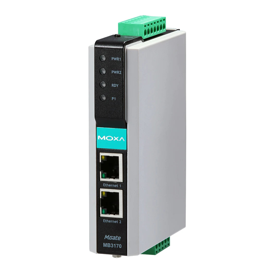
- Page 2 Overview The MGate MB3170 and MB3270 are 1 and 2-port advanced Modbus gateways that convert between Modbus TCP and Modbus ASCII/RTU protocols. They can be used to allow Ethernet masters to control serial slaves, or to allow serial masters to control Ethernet slaves. Up to 32 TCP masters and 31 serial slaves can be connected simultaneously.
- Page 3 Release the reset button when the Ready LED stops blinking. Panel Layouts The MGate MB3170 has a male DB9 port and a terminal block for connecting to serial devices. The MGate MB3270 has two DB9 connectors for connecting to serial devices.
- Page 4 Hardware Installation Procedure STEP 1: Use a standard straight-through Ethernet (fiber) cable to connect the unit to a network hub or switch. STEP 2: Connect your device to the unit's serial port. STEP 3: Mount the unit on a DIN-rail. STEP 4: Connect the power source to power input.
- Page 5 Power Input and Relay Output Pinouts Shielded Power Power N.O. Common N.C. Power Power Ground Input 1 Input 1 Input 2 Input 2 Optical Fiber Interface 100BaseFX Multi-mode Single-mode 50/125 μm Fiber Cable Type G.652 800 MHz*km Typical Distance 4 km 5 km 40 km Typical (nm)
- Page 6 Relay Output 1 digital relay output to alarm (normal close): current carrying capacity 1 A @ 30 Hazardous Location UL/cUL Class 1 Division 2 Group A/B/C/D, ATEX Zone 2, IECEx This device complies with Part 15 of the FCC rules. Operation is subject to the following conditions: 1.
Need help?
Do you have a question about the MGate MB3170 and is the answer not in the manual?
Questions and answers