Roland EXR-5 Service Note
Interactive arranger
Hide thumbs
Also See for EXR-5:
- Owner's manual (136 pages) ,
- Reference manual (2 pages) ,
- Supplementary manual (1 page)
Table of Contents
Advertisement
Oct.2003
EXR-5
interactive arranger
TABLE OF CONTENTS
Copyright © 2003 by ROLAND CORPORATION
All rights reserved. No parts of this publication may be reproduced in any form whithout the written permission of
ROLAND CORPORATION.
10/13
16/22
SN00072
2
3
4
6
7
8
14
14
14
15
15
24
26
28
30
32
34
36
37
K6018540
SERVICE NOTES
First edition
Issued by RES
Printed in Italy
EXR-5
38
40
42
44
45
46
45
46
45
46
48
48
Advertisement
Table of Contents

Related Manuals for Roland EXR-5


Summary of Contents for Roland EXR-5
-
Page 1: Table Of Contents
CIRCUIT DIAGRAM (MAIN 5/6 - FDC section) CIRCUIT DIAGRAM (MAIN 6/6 - USB section) Copyright © 2003 by ROLAND CORPORATION All rights reserved. No parts of this publication may be reproduced in any form whithout the written permission of ROLAND CORPORATION. -
Page 2: Specifications
Oct.2003 SPECIFICATIONS Keyboard: 61 keys, velocity sensitive Sound source: PCM samples Max polyphony: 64 voices Tones: 510 panel sounds + 542 XG compatible voices + 256 GM2 compatible sounds Drum Kits: 20 Drum Kits, 11 XG-compatible Drum Kits + 9 GM2- compatible Drum Kits Multitimbral parts: 19 Compatibility: GM2, GS, XG Lite Display type: New large backlit custom display... -
Page 3: Disassembly
EXR-5 DISASSEMBLY... -
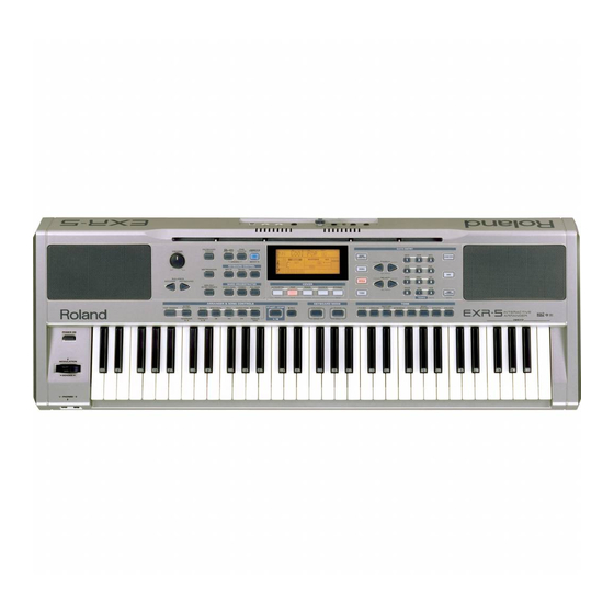
Page 4: Location Of Controls
Oct.2003 EXR-5 LOCATION OF CONTROLS Rear view... -
Page 5: Exploded View (Top)
Part No. Description J240910601 FLOPPY D.DRIVER JU-257A167P 22265242 RUBBER GUIDE BUSHING 22165134 BRASS BUSHING 7775301000 CPU ASSY (MICRO ROM) EXR-5 7626921001 61 KEY KEYBOARD TP/7BA 2ND VOLUME PCB ASSY EXR-5 7775305000 7775306000 C.S. SWITCH ASSY EXR-5 7775304000 HEADPHONE PCB ASSY EXR-5... -
Page 6: Exploded View (Bottom)
EXR-5 EXPLODED VIEW - BOTTOM Part No. Description K2418125 LOUDSPEAKER MM130 4OHM RIF.2313 K2358105 PRESSURE RUBBER K2018129 BOTTOM CABINET WITH BOX EXR-5 (SCREW) J2289186 SCREW 3,5x16 TCPR TFR H.8 BRUN... -
Page 7: Keyboard Parts List
Oct.2003 EXR-5 KEYBOARD PARTS LIST 61 KEY TP/7BA 2° KEYBOARD ASSY code 7626921001 PARTS NAME CODE RJA Num. DOUBLE HEADED SPRING 22178226 NATURAL KEY C5 J2579123 NA A KEY D6 J2579124 NA A KEY E7 J2579125 NATURAL KEY F1 J2579126... -
Page 8: Parts List
MB=Main Board, PHB=Phones Board, JKB=Jack Board, VB=Volume Board, CB=Control Board CASING Q.ty K2248187 RIGHT/LEFT LOUDSPEAKER GRILL EXR-5 K2198114 PLASTIC MUSIC REST EXR-5 K2018129 BOTTOM CABINET WITH BOX EXR-5 7775310000 SILKSCREENED PLEXIGLASS EXR-3/5 7775315000 VARN.+SILK.TOP CBNT EXR-5 KNOB BUTTON K2478265 BLACK KNOB 1420 E/D. - Page 9 IC10 on JKB 00562601 I.C. LA4705 POWER AMP IC4 on JKB 7775307000 I.C. MICRO IC2 CPU EXR-5 IC2 on MB 7775308000 I.C. FLEX ROM IC26 CPU EXR-5/EXR-3 IC26 on MB TRANSISTOR 15129114 TRANSISTOR 2SC-1815GR Q18,6 on JKB 15129136 TRANSISTOR 2SC-2878-A/B...
- Page 10 Oct.2003 J3809139 OXIDE RESISTOR 2.2 OHM 3W R78,83 on JKB 01783623 RESIST. 2010 10 OHM1/2W 5% R210,89 on MB POTENTIOMETER 00459901 ROT. POT. 10KB 14K 1230 VR1 on VB CAPACITOR J3629144 ELCTRL.COND. 470UF 16V AX C5 on CB 13639154 ELECTRL.COND.-V 1000UF 16V on JKB J3469156...
- Page 11 EXR-5 PACKING K2678105 CARTENE ENVELOPE HD 140X57 K2678106 POLYETH.ENVELOPE 4OX55 K2618298 OUTER PACKING EXR-5 K2638300 RIGHT POLY. END SIDE EXR-5 K2638301 LEFT POLY. END SIDE EXR-5 MISCELLANEOUS J2289113 NUT 3MA H.3 J2139102 TOOTHED WASHER I/D 3 22165134 BRASS BUSHING K2268185...
-
Page 12: How To Save How To Version Up
Oct.2003 HOW TO SAVE HOW TO VERSION UP HOW TO SAVE – HOW TO VERSION UP Since EXR-5 has a flash memory for the System Program registration, you can update it by floppy disk. Items Required: SOFTWARE UPDATE DISK 1 EXR-5... -
Page 13: How To Update The Software
EXR-5 HOW TO UPDATE THE SOFTWARE HOW TO UPDATE THE SOFTWARE VERSION Turn the power on while keeping the buttons FUNCTION and 2 pressed. The display visualizes: Ins Dsk#1 Insert Disk 1 into the Floppy Disk Drive. Then the display visualizes:... -
Page 14: Test Mode
Oct.2003 TEST MODE TEST STRUCTURE The general test menu has a hierarchical structure. You can get back to each menu page or up to the MAIN MENU page. The button 0 (0 = EXIT) allows you to interrupt any test except for: Rom Test Ram Test Test... - Page 15 EXR-5 SWITCH TEST Pressing button 1, you enter the Switch test: Press the buttons on the control panel one by one in sequence. The display visualizes the name of the button pressed and you hear a sound. The switch test ends when all the control panel’s buttons have been pressed and the system goes automatically back to the main menu (Sw, Le, Lc, Be).
- Page 16 Go to main menu and press button 2. The display visualizes: Foot MIDI Connect a Sustain Pedal (ie.:DP-2) to EXR-5 FOOT SWITCH output. Press button 1 to select the pedal test. Nothing is visualized on the display. Press and release the pedal. The display visualizes: XXX: ON if the pedal is full pressed;...
- Page 17 EXR-5 (FD) Floppy Disk Test Pressing button 3, the display visualizes: FD TEST Then: Insert Disk Insert an unprotected and formatted HD floppy disk into the floppy disk driver. After a few seconds the display visualizes: OK or Er The system automatically writes and reads the disk.
- Page 18 Oct.2003 Pressing button 1, the display visualizes: SINE Test procedure: Insert a stereo jack into the headphones socket; Put the volume potentiometer at max; Check by an oscilloscope that the signals at the stereo jack have the following values (tolerance +/- 5%): LEFT RIGHT Amplitude 3,10Vpp...
- Page 19 EXR-5 Effect Test On Audio Test menu, pressing button 3, the display visualizes: REV CHO Pressing button 1, you select REVERB TEST; Pressing button 2, you select CHORUS TEST; Reverb test Pressing button 1, the display visualizes: Reverber You hear a reverbered drum sound from the loudspeakers.
- Page 20 Oct.2003 Then, the display visualizes the test result: Ok: test succeeded Er: test failed To exit press button 0 (Exit). Pressing button 2 (to enter Ra), the display visualizes: Wait Then, the display visualizes the test result: Ok: test succeeded Er: test failed Fl test is deactivated.
-
Page 21: Block Diagram
Oct.2003 EXR-5 BLOCK DIAGRAM PHONES BOARD IC47 LINE MAIN BOARD IC14 FOOTSWITCH MIDI SOUND OUTPUT JACK DATA BOARD GENERATION LOUT ROUT 24.576MHz IC31 PHOTO BUFFER Q4,Q17,Q18 Q2,Q3 MUTE SQUELCH CNTRL IC24 MUTE BUFF. IC28 IC26 RESET UCAS IC8,IC5 64 M... -
Page 22: Circuit Board (Main)
Oct.2003 CIRCUIT BOARD (MAIN) View from component side... - Page 23 EXR-5 CIRCUIT BOARD (MAIN) View from solder side...
-
Page 24: Circuit Diagram (Main 1/6)
Oct.2003 EXR-5 CIRCUIT DIAGRAM (MAIN 1/6) 5 VD R A3 4X47s 5VREF 33uF16s R A4 4X47s DA204K R A6 4X47s R A7 4X47s R A9 4X47s RA12 4X47s 5VREF DA204K RA13 4X47s RA15 4X47s RA16 4X47s BENDER R115 100s A N7... -
Page 25: Circuit Diagram (Main 2/6 - Xp Section)
Oct.2003 EXR-5 CIRCUIT DIAGRAM (MAIN 2/6 - XP SECTION) C306 3. 3 100nFs R179 WCS0 W3CS0 NI U XWOE XW3OE XWOE XW3OE WA23 W3A23 RA43 WA23 W3A23 WA22 W3A22 4X0s WA22 W3A22 WA21 W3A21 NI U WA21 W3A21 WA20 W3A20... -
Page 26: Circuit Diagram (Main 3/6 - Key Section)
Oct.2003 EXR-5 CIRCUIT DIAGRAM (MAIN 3/6 - KEY SECTION) SC[0..4] S C0 S C1 S C2 B R0_M RA49 B R1_M 4X0s NIU S C4 B R2_M B R3_M RA50 B R4_M 4X0s NIU 22pFs NIU B R5_M C353 22pFs NIU... -
Page 27: Circuit Diagram (Main 4/6 - Memory Section)
Oct.2003 EXR-5 CIRCUIT DIAGRAM (MAIN 4/6 - MEMORY SECTION) STYLE FLASH ROMs R114 IC1A TC74VHC139F 10Ks D 15 D 15 DQ15 DQ15 D 14 D 14 DQ14 DQ14 D 13 D 13 DQ13 DQ13 XFLASH2 D 12 D 12 DQ12... -
Page 28: Circuit Diagram (Main 5/6 - Fdc Section)
Oct.2003 CIRCUIT DIAGRAM (MAIN 5/6 - FDC SECTION) -
Page 29: Circuit Diagram (Main 6/6 - Usb Section)
EXR-5 CIRCUIT DIAGRAM (MAIN 6/6 - USB SECTION) -
Page 30: Circuit Board (Jack)
Oct.2003 EXR-5 CIRCUIT BOARD (JACK) View from component side... -
Page 31: Circuit Diagram (Jack)
Oct.2003 EXR-5 CIRCUIT DIAGRAM (JACK) C103 100pF np0 C104 R116 10uF16BP R115 D+5V C105 YKF51-5054 R117 R118 100uF25 R119 680k 1SS133 2SC2878 IC9B D+5V FBR07HA850TB-00 M5218AL 53014_0710 IC1C DAMPER IC1D FLAT HD74LS04P NI U HD74LS04P R120 Right L eft DTA114ES... -
Page 32: Circuit Board (Control)
Oct.2003 EXR-5 CIRCUIT BOARD (CONTROL) View from component side... -
Page 33: Circuit Diagram (Control)
Oct.2003 EXR-5 CIRCUIT DIAGRAM (CONTROL) VLED SSC[0..7] RN2227 S SC0 L LSC0 0 NIU VLED Orange Orange Orange Orange Orange Orange Orange Orange MUSIC STRINGS KEYB. TOUCH ORIGINAL ROCK ASSIST. S SC1 RN2227 ROCK ACOUSTIC DANCE ETHNIC FUNCTION DISK USER PROG. -
Page 34: Circuit Board (Phones)
Oct.2003 EXR-5 CIRCUIT BOARD (PHONES) CIRCUIT DIAGRAM (PHONES) 53014_0710 Right Le ft AGND MuteSend MuteRet MuteSend_1 MuteSend_1 MuteRet_1 YKB21_5078 To JACK PCB ASSY (CN8) MuteRet_1 JK10 YKB21_5078 View from component side 100nFC CIRCUIT BOARD (VOLUME) CIRCUIT DIAGRAM (VOLUME) MASTER VOLUME... -
Page 35: Circuit Board (Right-Left Contact)
Oct.2003 EXR-5 CIRCUIT BOARD (RIGHT - LEFT CONTACT w/RUBBER View from solder side CIRCUIT DIAGRAM (RIGHT CONTACT) CIRCUIT DIAGRAM (LEFT CONTACT)
Need help?
Do you have a question about the EXR-5 and is the answer not in the manual?
Questions and answers