Table of Contents

Summary of Contents for Hellenbrand H-151 Series
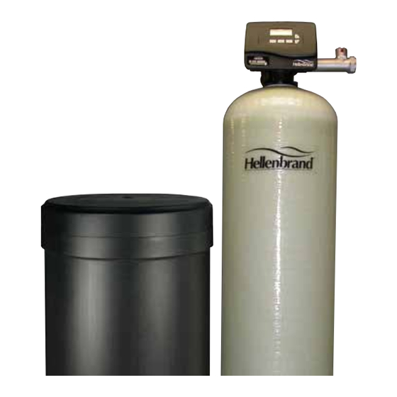
- Page 1 Water Management System - Patent Pending Owner’s Manual 800396 Rev B 10/17/17-LBRY ©2011-2017 Manufactured by: HELLENBRAND, INC. 404 Moravian Valley Road Waunakee, Wisconsin 53597-2509 Web: www.hellenbrand.com • Email: info@hellenbrand.com...
-
Page 2: Table Of Contents
This owner’s manual is designed to assist owners and installers with the operation, maintenance and installation of your new water softener. It is our sincere hope that this manual is clear, concise and helpful to both owner and installer. We have included detailed in- structions on general operating conditions, pre-installation and installation instructions, start-up, and timer and meter programming. -
Page 3: Job Specification Sheet
JOB SPECIFICATION SHEET MODEL NO. __________________________________________________________________________________________ *WATER TEST AT TIME OF INSTALLATION _______ Hardness CaCo (gpg) ______ Other______________________ _______ Iron (ppm) ______ Other______________________ _______ pH ______ Other______________________ OPTIONAL RELAY SETTINGS _______ Off ______ Reclamation mode enabled ______ No Hard By-pass enabled ______ Alternator system enabled ______ Demand Recall Relay 1... -
Page 4: Soft Water Basics
SOFT WATER BASICS Hardness Excess amounts of calcium and magnesium in water produce hardness. A water softener removes the majority of calcium and magnesium to produce softened water. Hardness is measured in terms of grains. (This grain weight is derived from the average weight of a dry grain of wheat.) When your water is tested, the grain hardness is calculated and expressed as grains per gallon (gpg). -
Page 5: Pre-Installation Check List
PRE-INSTALLATION CHECK LIST (All electrical & plumbing should be done in accordance to all local codes) free from lime and iron build-up. Piping that is built-up heavily Water Pressure: A minimum of 25 pounds of water pressure with lime and/or iron must be replaced. If piping is blocked with (psi) is required for regeneration. -
Page 6: Installation Instructions
INSTALLATION INSTRUCTIONS (All electrical & plumbing should be done in accordance to all local codes) 5. The brine refill flow control assembly is installed in an easy • Do not use vaseline, oils, other hydrocarbon lubricants or to access refill elbow located on top of the control valve. spray silicone anywhere. - Page 7 INSTALLATION DIAGRAMS TOP VIEW Typical Single Unit Typical Twin Unit Installation Piping Installation Piping PROGRAMMING TWIN ALTERNATING SYSTEM WITH MOTORIZED AUXILIARY VALVE (MAV) When control is programmed as ALT A & ALT B signifying to PC board to operate an alternating system, factory default for reserve setting is "AUTO"...
-
Page 8: Programming
PROGRAMMING General Information The H151 control valve is the “brain” of your water softener. It consists of the valve body and powerhead with solid state microprocessor. The display panel (see Figure 7) consists of the LCD display and five push buttons which are used in displaying and program- ming the water softener settings. - Page 9 SET TIME OF DAY = Up Arrow = Down Arrow STEP 1 Step 1 - Press SET CLOCK. Step 2 - Current Time (hour): Set the hour of the day using or buttons. AM/PM toggles after 12. Press NEXT to go to step 3.
- Page 10 Manual Regeneration "REGEN TODAY" CAPACITY REMAINING Sometimes there is a need to regenerate the system, sooner than when the system calls for it, usually referred to as manual regeneration. There may be an unexpected period of heavy water usage. To initiate a manual regeneration at the preset delayed regeneration time, press and release “REGEN”.
- Page 11 STEP 3S – Select the time for the first cycle (which in this example is BACKWASH) using the BACKWASH TIME STEP 3S or button. Press NEXT to go to Step 4S. Press REGEN to return to the previous step. 10:00 STEP 4S –...
- Page 12 STEP 10S – Set Relay to activate by Time, Gallons, Regen Gallons, Off or Service Alarm by using RELAY 1 "TIME" STEP 10S or buttons. A relay can be used to operate a chemical feed pump or solenoid. The choices are: TRIGGER •...
- Page 13 STEP 17S – Use up and down arrows to select number of gallons per relay activation of regen RELAY 1 SET POINT STEP 17S gallon setting. Range: 1 -100 gallons. Press NEXT to go to Step 18S. STEP 18S – If Off or Time was selected in previous steps, this screen does not appear.
- Page 14 DIAGNOSTICS To reset diagnostic data push “Next” and button until TYPE appears in window, then press “ & ” button simultaneously for 3 seconds. STEP 1D – Press or simultaneously for three seconds. If screen in step 2D does not appear in 5 STEP 1D seconds the lock on the valve is activated.
- Page 15 VALVE HISTORY (Can not be reset) STEP 1VH – Press and simultaneously for three seconds and release, then press STEP 1VH and simultaneously and release. If screen in step 2VH does not appear in 5 seconds the lock on the valve is activated.
- Page 16 CYCLE SEQUENCE Anytime cycle sequence is modified, softener set-up will revert to Cycle Options manufacturer setting and must be reprogrammed as desired. REGENERANT FILL BACKWASH DRAW-DN Cycle Sequence instructions allows the operator to set the order of the cycle. The Softener System Setup allows the operator to set how long RINSE SOFTENING the cycles will last.
- Page 17 Confi guring the Control Valve to operate with Clack System Controller: SYSTEM BOARD STEP 9CS – Configuring the Control Valve to operate with the Hellenbrand System STEP 9CS Select System Board Enabled to link the Control Valve to the Clack System Controller. For...
- Page 18 Only use Clack Motorized Alternating Valves (MAV) with these selections. Clack No Hard Water Bypass Valves (1” or 1.25” V3070FF or V3070FM) are not designed to be used with the reclaim or separate source functions. Press NEXT to go to Step 6CS. Press REGEN to return to previous step. AUX RECLAIM DURATION AUX RECLAIM DURATION AUX RECLAIM DURATION...
- Page 19 STEP 15CS – Press the or buttons until selection of first cycle appears in left upper corner, in this BACKWASH STEP 15CS CYCLE 1 example BACKWASH is selected. Press NEXT to go to Step 16CS. Press REGEN to return to previous step.
-
Page 20: Water Softener Disinfection
WATER SOFTENER DISINFECTION The construction materials of your water softener will not support White Sail and Eagle Brand Bleach. If stronger solutions are bacterial growth nor will these materials contaminate a water used, such as those sold for commercial laundries, adjust supply. -
Page 21: Trouble Shooting
TROUBLE SHOOTING PROBLEM CAUSE CORRECTION After resolving the cause of any error code or any service work on valve, press NEXT & REGEN simultaneously for 5 seconds or disconnect power supply for 5 seconds at PC board and reconnect to resynchronize software with piston position. 1. - Page 22 TROUBLE SHOOTING PROBLEM CAUSE CORRECTION 3. Control valve does not regenerate A. Transformer unplugged A. Connect transformer automatically when REGEN button B. No electric power at outlet B. Repair outlet or use working outlet is depressed and held C. Broken drive gear or drive cap assembly C.
- Page 23 TROUBLE SHOOTING PROBLEM CAUSE CORRECTION 15. Control does not display correct A. Power outage < 2 years, time of day flashing, A. Reset time of day, replace lithium coin type battery on battery depleted circuit board 16. No “softening” or “filtering” display A.
-
Page 24: Conditioner And Salt Assemblies
H151 CONDITIONER & BRINE TANK ASSEMBLIES Item Description Part # Control Center Metered 104228 Upper Baffle Diffuser 4" Top Tank 101489 Items required with 6" top flanged tanks Top Diffuser 6" Flanged Top Tank 101490 Screw Diffuser Retaining 102461 Adapter Kit 6x4 100316 3&4 Mineral Tank Assembly... -
Page 25: Meter Specs
INLINE FLOW METERS 1.5” Meter Assembly 1.0” Meter Assembly, Less Fittings p/n 102049 p/n 108566 DRAWING NO. ORDER NO. DESCRIPTION ORDER NO. DESCRIPTION DRAWING NO. 102075 Remote Meter Assembly 102075 Remote Meter Assembly V3118-03 Turbine Assembly 109586 Turbine Assembly 102165 O’Ring-215 102165 O’Ring-215... -
Page 26: Parts Diagrams
FRONT COVER AND DRIVE ASSEMBLY DRAWING NO. ORDER NO. DESCRIPTION QUANTITY 103463 Front Cover Assembly Black 102096 Motor Assembly 101262 Drive Bracket & Spring Clip 109807 PC Board 101746 Drive Gear 12x36 101459 Drive Gear Cover Relay Kit Options: Optional 103724 PCM Relay Installed Relay Kit... - Page 27 DRIVE CAP ASSEMBLY, DOWN FLOW PISTON, REGENERANT PISTON AND SPACER STACK ASSEMBLY QUANTITY DRAWING NO. ORDER NO. DESCRIPTION 101613 H151 Drive Cap Assembly 102167 O-Ring 228 102291 H151 Piston Downflow Assy 102296* H151 Regenerant Piston 101609 H151 Backplate Dowel 102547 H151 Spacer Stack Assy 101189 Back Plate...
- Page 28 Insert the injector feed and draw tubes into the main body, bottoming them out in their bores. Install the injector screen in the regenerant body, the small hole in the end of the screen will nest around a feature in the plastic body allowing the large end to be flush with a step in the tube bore.
- Page 29 DRAIN LINE - 3/4” QTY. ITEM NO. DESCRIPTION ORDER NO. Proper DLFC orientation 101414 Locking Clip directs water flow towards the washer face with 101159 H151 DLFC Adapter rounded edge. 101618 H151 Drain Elbow 3/4" 102153 O-ring 019 Water Flow 102406 DLFC Retainer Assy 101583...
-
Page 30: Flow Diagrams
FLOW DIAGRAM – SERVICE Drain Inlet Outlet Regenerant Draw Distributor 1 Service FLOW DIAGRAM – BACKWASH Drain Inlet Outlet Regenerant Draw Distributor 2 Backwash... - Page 31 FLOW DIAGRAM – DRAW Drain Inlet Outlet Regenerant Draw Distributor Injector Feed Water From Inlet 3 Draw Regenerant Mix Enters Top Of Tank Section Through Injector FLOW DIAGRAM – RINSE Drain Inlet Outlet Regenerant Draw Distributor 4 Rinse...
-
Page 32: Flow Diagrams
FLOW DIAGRAM – FILL Drain Inlet Outlet Regenerant Draw Distributor 5 Fill... -
Page 33: Programing Options
PROGRAMMING OPTIONS Reserve Days Regeneration Results Gallons Type Override (Reserve capacity estimate based on history of water usage) Reserve capacity automatically estimated. AUTO Delay Regeneration occurs when gallons capacity falls below the reserve capacity at the next Regen Set Time. Reserve capacity automatically estimated. -
Page 34: Service Instructions
SERVICE INSTRUCTIONS Drive Assembly Replace broken or damaged drive gears. Do not lubricate any of Remove the valve cover to access the drive assembly. the gears. Avoid getting any foreign matter on the reflective coating because dirt or oils may interfere with pulse counting. Disconnect the power source plug (black wire) from the PC board The drive gear cover only fits on one way, with the large clip orientated prior to disconnecting the motor or water meter plugs from the PC... - Page 35 Reattach the main piston to the drive cap assembly. Reattach the regenerant piston (if needed) to the main piston. Do not lubricate the piston rod, main piston or regenerant piston. Lubricant will adversely affect the clear lip seals. Reinsert the drive cap assembly and piston into the spacer stack assembly and hand tighten the drive cap assem- bly.
-
Page 36: Injector Flow Rate Graphs
INJECTOR FLOW RATE GRAPHS VIOLET, ORDER NO. TBD WHITE, ORDER NO. 101812 US Units US Units BLUE, ORDER NO. 101813 RED, ORDER NO. 101811 US Units US Units... - Page 37 INJECTOR FLOW RATE GRAPHS YELLOW, ORDER NO. 101814 ORANGE, ORDER NO. 101816 US Units US Units GREEN, ORDER NO. 101815 GREY, ORDER NO. 109741 US Units US Units...
-
Page 38: Specifications
H151 SPECIFICATIONS H151 (SUPER HP) Specifications H151 H151 H151 H151 H151 H151 H151 Model # 150-21 180-21 Factory Regeneration Settings Backwash Minutes Gallons Brine/Rinse Minutes Gallons Fast Rinse Minutes Gallons Total Regeneration Gallons Refill LBS / Minutes Lbs. Min. Lbs. Min. Lbs. - Page 39 H151 SPECIFICATIONS H151 (Super HP) Specifications H151 H151 H151 H151 H151 H151 Model # 300-30 Factory Regeneration Settings Backwash Minutes Gallons Brine/Rinse Minutes Gallons Fast Rinse Minutes Gallons Total Regeneration Gallons Refill LBS / Minutes Lbs. Min. Lbs. Min. Lbs. Min. Lbs.
-
Page 40: Warranty
If the System or any part described above becomes defective within the specified warranty period, you should notify your local authorized seller of Hellenbrand products, and arrange a time during normal business hours for the inspection of the System at the original installation site. You may also contact Hellenbrand and we will provide you with the contact information for your local authorized seller of Hellenbrand products.
Need help?
Do you have a question about the H-151 Series and is the answer not in the manual?
Questions and answers