Precor Discovery Series Assembly Manual
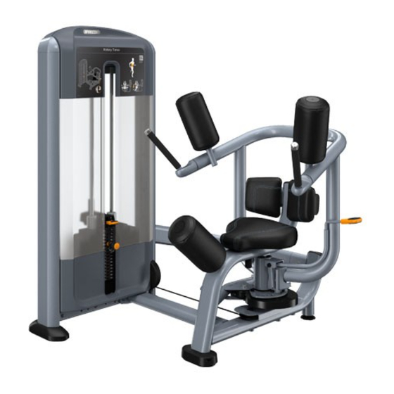
Selectorized line, rotary torso
Hide thumbs
Also See for Discovery Series:
- Owner's manual (44 pages) ,
- Assembly manual (10 pages) ,
- Getting started manual (2 pages)
Table of Contents
Advertisement
Quick Links
Download this manual
See also:
Owner's Manual
Advertisement
Table of Contents

Related Manuals for Precor Discovery Series


Summary of Contents for Precor Discovery Series
- Page 1 Discovery™ Series Selectorized Line Rotary Torso Assembly Guide Equati on 1: E nglis h...
-
Page 3: Assembly Requirements
At least two people are required to assemble the equipment. DO NOT attempt assembly by yourself. Precor recommends that the strength equipment be bolted down at all anchoring points. See Bolt equipment to the floor for more details. Installation Requirements Follow these installation requirements when assembling the unit: Unpack the box and assemble the equipment close to where you plan to use it. - Page 4 4. Attach the cross support to the weight tower using the fasteners removed Attaching the weight tower to the movement frame previously. Partially tighten the fasteners. Note Do not tighten fasteners until instructed to do so. Note Be sure to orient the dome washers as shown in the following figure. Have your assistant hold the equipment frame in an upright, balanced position while you complete the following procedure.
-
Page 5: Stabilize Equipment
Tighten all frame fasteners Stabilize equipment Once you have completed assembly, make sure all loose bolts are fully tightened. CAUTION To prevent damage to the equipment foot, tighten it all the way Refer to bullets (below) for bolt torques. into the frame before moving the equipment. Note Begin with the bolts located on the cross support. -
Page 6: Route The Cable Assembly
Route the cable assembly To route the cable on the movement frame: The cable is wrapped in packing material and attached to the equipment frame for shipment. Proper cable routing is shown in the following figure. Using a #2 Phillips bit, remove the pulley covers and screws. Check that the cable is properly routed on the movement frame. - Page 7 Route the cable on the weight tower Gently lift the kick cover and set it aside. The weight tower ships with the kick cover and pulley cover attached. 4. Using a 5/32-inch hex bit, remove the shoulder bolt next to the pulley. Route To route the cable on the weight tower: the cable around the pulley, then replace and tighten the shoulder bolt with 8 Using a 5/32-inch hex bit, remove the screw and pulley cover and set them...
- Page 8 Thread the cable through the top frame of the weight tower Thread the cable up through the weight tower frame. Replace the pulley and The cable passes through an opening in the top of the weight tower frame, over cable retainer making sure that the cable is positioned in the pulley trough and the pulleys and then back down through the frame to the weight stack.
- Page 9 To attach the cable to the weight stack Adjust the cable tension Thread the cable down through the opening under the second pulley, as To adjust the cable tension: shown in the following figure. Insert the cable bolt into the selector stem until the cable meets the following requirements: The top weight begins to separate from the second weight.
- Page 10 Standards occasionally change or are updated. Precor recommends that you keep Verify operation of the equipment apprised of your local industry standards. Precor shall not be held liable for failure to properly bolt the strength equipment to the floor. Once assembly is complete, verify safe operation by checking the following points: Cable tension is correct and the cable is moving smoothly on its pulleys.
- Page 12 DSL Rotary Torso AG | P/N CW39933-103 rev C, ENU ©2017 Precor Incorporated | July 2017...
Need help?
Do you have a question about the Discovery Series and is the answer not in the manual?
Questions and answers