Gefen EXT-3GSDI-441 User Manual
4x1 3gsdi switcher
Hide thumbs
Also See for EXT-3GSDI-441:
- User manual (17 pages) ,
- User manual (13 pages) ,
- User manual (18 pages)
Table of Contents
Advertisement
Quick Links
Advertisement
Table of Contents

Subscribe to Our Youtube Channel
Related Manuals for Gefen EXT-3GSDI-441


Summary of Contents for Gefen EXT-3GSDI-441
- Page 1 *Preferred 4x1 3GSDI Switcher EXT-3GSDI-441 User Manual Release A8...
- Page 2 Important Safety Instructions Read these instructions. Keep these instructions. Heed all warnings. Follow all instructions. Do not use this unit near water. Clean only with a dry cloth. Do not block any ventilation openings. Install in accordance with the manufacturer’s instructions.
- Page 3 Gefen warrants the equipment it manufactures to be free from defects in material and workmanship. If equipment fails because of such defects and Gefen is notified within two (2) years from the date of shipment, Gefen will, at its option, repair or replace the equipment, provided that the equipment has not been subjected to mechanical, electrical, or other abuse or modifications.
-
Page 4: Technical Support
Technical Support (818) 772-9100 (800) 545-6900 8:00 AM to 5:00 PM Monday - Friday, Pacific Time (818) 772-9120 Email support@gefen.com http://www.gefen.com Mailing Address Gefen, LLC c/o Customer Service 20600 Nordhoff St. Chatsworth, CA 91311 Product Registration Register your product here: http://www.gefen.com/kvm/Registry/Registration.jsp... - Page 5 4x1 3GSDI Switcher is a trademark of Gefen, LLC. © 2015 Gefen, LLC. All Rights Reserved. All trademarks are the property of their respective owners. Gefen, LLC reserves the right to make changes in the hardware, packaging, and any accompanying documentation without prior written notice.
-
Page 6: Packing List
Packing List The 4x1 3GSDI Switcher ships with the items listed below. If any of these items are not present in the box when you first open it, immediately contact your dealer or Gefen. • 1 x 4x1 3GSDI Switcher •... -
Page 8: Table Of Contents
Table of Contents Getting Started Introduction......................2 Front / Rear / Bottom Panel ................2 IR Remote Control ..................4 Installing the IR Remote Battery ..............6 Setting the IR Remote Channel ..............6 Installation ......................7 Connection Instructions ................. 7 Sample Wiring Diagram ................ -
Page 11: Getting Started
4x1 3GSDI Switcher Getting Started Introduction......................2 Front / Rear / Bottom Panel ................2 IR Remote Control ..................4 Installing the IR Remote Battery ..............6 Setting the IR Remote Channel ..............6 Installation ......................7 Connection Instructions ................. 7 Sample Wiring Diagram ................ -
Page 12: Introduction
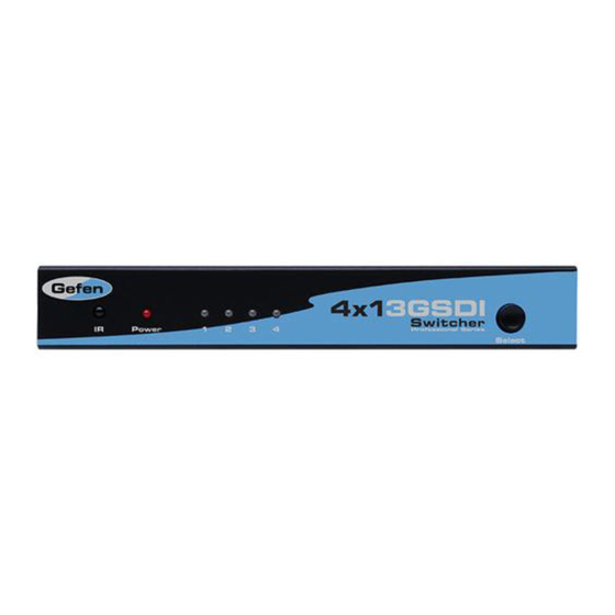
Introduction Page Title Front / Rear / Bottom Panel ® 4x1 3GSDI Switcher Power Select EXT-3GSDI-441 ® 4x1 3GSDI Switcher Power Select In 1 In 2 In 3 In 4 RS-232 5V DC ® 4x1 3GSDI Switcher Power Select EXT-3GSDI-441... - Page 13 Introduction Page Title Name Description Receives signals from the included IR remote control. Power This LED indicator will glow solid blue when the matrix is powered. Input Indicators (1 - 4) These LED indicators display the currently selected input. The currently selected input will glow solid blue.
-
Page 14: Ir Remote Control
Introduction IR Remote Control Name Description Activity indicator This LED will be activated momentarily each time an input button is pressed. Input buttons Press these buttons to select an input (1 - 4). page | 4... - Page 15 Introduction P/N: RMT-4-IRN www.gefen.com Name Description DIP switch bank Use these DIP switches to set the IR channel of the remote. See the next page for more information. Primary battery slot Holds the battery for operating the remote. (shown without battery) Use only 3V CR2032-type batteries.
-
Page 16: Installing The Ir Remote Battery
Setting the IR Remote Channel P/N: RMT-4-IRN In order for the included IR remote control to communicate with the 4x1 3GSDI Switcher, www.gefen.com the IR remote control must be set to the same channel as the switcher. IR Channel DIP settings... -
Page 17: Installation
Connect the included power supply to the 5V DC power receptacle and connect the power cord to an available electrical outlet. Sample Wiring Diagram 3G-SDI CABLE RS-232 CABLE 3G-SDI Source 3G-SDI Source RS-232 Automation Control Device 3G-SDI Source Switcher 3G-SDI Source 3G-SDI Display EXT-3GSDI-441 page | 7... -
Page 19: Basic Operation
4x1 3GSDI Switcher Basic Operation Switching Sources ....................10 Using the Front Panel ................. 10 Using the IR Remote ................... 11 DIP Switch Configuration ..................12... -
Page 20: Switching Sources
(In 1 - In 4) on the rear of the unit. The input indicator, for the currently selected source, will glow solid blue. EXT-3GSDI-441 Press and release the Select button on the front panel to advance to the next input. -
Page 21: Using The Ir Remote
Using the IR Remote Input indicators ® 4x1 3GSDI Switcher Power Select IR sensor EXT-3GSDI-441 Point the IR remote at the IR sensor, located on the front panel of the matrix. In 1 In 2 In 3 In 4 RS-232 5V DC Select the desired input (1 - 4) on the IR remote control unit. -
Page 22: Dip Switch Configuration
DIP Switch Configuration EXT-3GSDI-441 The 4x1 3GSDI Switcher contains a bank of four DIP switches, located on the bottom of In 1 In 2 In 3 In 4 RS-232 5V DC the unit. The DIP switch bank is covered by a piece of plastic tape. Remove the tape to expose the DIP switch bank. - Page 23 DIP Switch Configuration DIP 3 DIP 4 Description Set switcher to IR channel 0 Set switcher to IR channel 1 Set switcher to IR channel 2 Set switcher to IR channel 3 Indicates factory-default settings. Important The IR channel assigned to the IR Remote Control must match the IR channel assigned to the 4x1 3GSDI Switcher.
-
Page 25: Advanced Operation
4x1 3GSDI Switcher Advanced Operation RS-232 Control....................16 RS-232 Interface ..................16 RS-232 Settings ..................16 Commands ......................17... -
Page 26: Rs-232 Control
RS-232 Control RS-232 Interface DE-9 DA-15 RS-232 Controller Switcher DB-25 Only TXD, RXD, and GND pins are used. DC-37 RS-232 Settings Description Setting 19200 Baud rate DD-50 Data bits None Parity Stop bits None Hardware flow control Important When sending an RS-232 command, a carriage return (0d) and a line feed (0a) must be included at the end of the command. -
Page 27: Commands
Commands Command Description Sets the source to Input 1 Sets the source to Input 2 Sets the source to Input 3 Sets the source to Input 4 Displays the currently selected input Example (If input 2 is the currently selected input) page | 17... -
Page 29: Appendix
4x1 3GSDI Switcher Appendix Specifications ...................... 20 page | 19... -
Page 30: Specifications
Specifications Connectors, Controls, and Indicators Video Input • 4 x BNC, female Video Output • 1 x BNC, female RS-232 • 1 x DB-9, female Select Button • 1 x tact-type Power Receptacle • 1 x locking Power Indicator • 1 x LED, blue Operational Power Supply... - Page 32 *Preferred Stretch it. Switch it. Split it. Gefen’s got it. ® 20600 Nordhoff St., Chatsworth CA 91311 20600 Nordhoff St., Chatsworth CA 91311 1-800-545-6900 1-800-545-6900 818-772-9100 818-772-9100 fax: 818-772-9120 fax: 818-772-9120 www.gefen.com www.gefen.com support@gefen.com support@gefen.com...
Need help?
Do you have a question about the EXT-3GSDI-441 and is the answer not in the manual?
Questions and answers