Table of Contents
Advertisement
Quick Links
Advertisement
Table of Contents

Related Manuals for Gefen EXT-DP-841


Summary of Contents for Gefen EXT-DP-841
- Page 1 ®...
- Page 3 Chatsworth, CA 91311 www.gefen.com support@gefen.com Notice Gefen, LLC reserves the right to make changes in the hardware, packaging, and any accompanying documentation without prior written notice. 8x1 DisplayPort Switcher is a trademark of Gefen, LLC © 2012 Gefen, LLC. All rights reserved.
-
Page 4: Table Of Contents
CONTENTS Introduction Operation Notes Features Front Panel Layout Front Panel Descriptions Back Panel Layout Back Panel Descriptions IR Remote Control Unit Layout and Description Installing the Battery 10 Configuring the IR Remote Control Unit 11 Connecting the 8x1 DisplayPort Switcher Wiring Diagram 12 Operating the 8x1 DisplayPort Switcher Front Panel Buttons and LED Indicators Switching sources using the front-panel buttons Switching sources using the IR Remote Control Unit... -
Page 5: Introduction
Easily switch between eight DisplayPort computers with the Gefen 8x1 DisplayPort Switcher. The Gefen 8x1 DisplayPort Switcher is a convenient, reliable and economical solution for using as many as eight DisplayPort equipped Mac or PC computers with a single DisplayPort Monitor. The unit offers multiple options for control including front panel buttons, an included IR remote, rear panel IR and RS-232 ports, and even an Ethernet port to accommodate IP control. -
Page 6: Operation Notes
OPERATION NOTES READ THESE NOTES BEFORE INSTALLING OR OPERATING THE 8X1 DISPLAYPORT SWITCHER • The 8x1 DisplayPort Switcher supports Pass-through EDID. The Switcher will use the EDID from the currently active input. • Dual Link resolutions up to 2560 x 1600 are supported. •... -
Page 7: Features
FEATURES Features • Supports 1080p Full HD at 120Hz and dual-link resolutions up to 2560 x 1600 (WQXGA) • Supports RGB and YCbCr color spaces • Front-panel switching using discrete select buttons • RS-232 port for automation • IR remote control (included) •... -
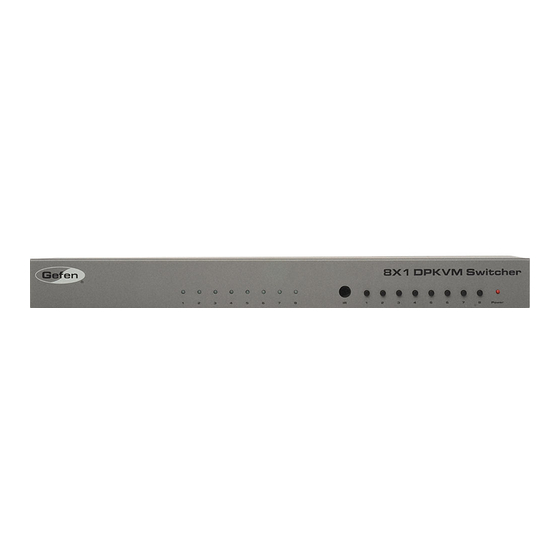
Page 8: Front Panel Layout
FRONT PANEL LAYOUT... -
Page 9: Front Panel Descriptions
FRONT PANEL DESCRIPTIONS Input Indicators (1 - 8) Each of these LED indicators glows bright blue according to the input selection (see Input Buttons, below) Receives I/R signal from the included IR Remote Control Unit. Input Buttons (1 - 8) Pressing each of these buttons selects the desired input source (1 - 8). -
Page 10: Back Panel Layout
BACK PANEL LAYOUT... -
Page 11: Back Panel Descriptions
BACK PANEL DESCRIPTIONS 5V DC Connect the included 5V DC locking power supply to this receptacle. In 1 - In 8 Each of these ports will accept a standard DisplayPort source device. DP Out This port will accept a single standard DisplayPort output device. The currently selected DisplayPort input source will be output via this port. -
Page 12: Ir Remote Control Unit
IR REMOTE CONTROL UNIT Layout and Description Activity Indicator This LED will be activated momentarily each time a button is pressed. Source Selection Buttons (1 - 8) These buttons are used to select which source is routed to a monitor. NOTE: An Activity Indictor that flashes quickly while holding down any one of the eight buttons indicates a low battery. - Page 13 IR REMOTE CONTROL UNIT Installing the RMT-8IR Battery Remove the battery cover on the back of the IR Remote Control Unit. Insert the included battery into the open battery slot. The positive (+) side of the battery should be facing up. Replace the battery cover.
- Page 14 IR REMOTE CONTROL UNIT How to Resolve IR Code Conflicts In the event that IR commands from other remote controls interfere with the supplied IR Remote Control unit, changing the IR Remote Control’s IR channel will fix the problem. The IR Remote Control unit has a bank of DIP switches used for setting the IR channel. The DIP switch bank is located underneath the battery cover.
-
Page 15: Connecting The 8X1 Displayport Switcher
OPTIONAL: To extend the range of the IR control, connect an IR Extender (Gefen part no. EXT-RMT-EXTIR) to the back of the Switcher. Connect the included 5V locking power supply to the power receptacle on the 8x1 DisplayPort Switcher Connect the opposite end of the power supply to an open wall socket power source. -
Page 16: Operating The 8X1 Displayport Switcher
OPERATING THE 8X1 DISPLAYPORT SWITCHER Front Panel Buttons and LED Indicators The front panel of the 8x1 DisplayPort Switcher has a set of eight (8) LED indicators, displaying which input (source) is being displayed. Each of these LED indicators corresponds to one of the push-buttons on the front panel. Switching sources using the front-panel buttons Example: Switch to input 2 using the front-panel buttons: Press button 2 on the front panel of the 8x1 DisplayPort Switcher. -
Page 17: Switching Sources Using Rs-232
OPERATING THE 8X1 DISPLAYPORT SWITCHER Switching sources using RS-232 Configure the Switch for use with RS-232 (see page 14 for details). Example: Switch to input 5 using RS-232 Use the command r 5 to route the Switcher to Input 5. See page 14 - 15 for important information on RS-232 commands. RS-232 commands are case-sensitive. -
Page 18: Rs-232 Control
RS-232 CONTROL Only pins 2 (Receive), 3 (Transmit), and 5 (Ground) are used for communication. A null-modem adapter should not be used with this product. 5 4 3 2 1 1 2 3 4 5 9 8 7 6 6 7 8 9 Only Pins 2 (RX), 3 (TX), and 5 (Ground) are used on the RS-232 serial interface Serial Port Settings Bits per second .................... -
Page 19: Rs-232 Commands
RS-232 COMMANDS Command Syntax All RS-232 commands are case-sensitive and must be entered in lowercase. Each command must be preceded by the ‘#’ character. A carriage return must also be appended to every command. Example: #set_http_port 80[CR] IP Configuration Command Description #get_pass Prompts for the Telnet password... - Page 20 RS-232 COMMANDS #GET_USER_NAME Command The #GET_USER_NAME command prompts for the Telnet username. Syntax: #get_user_name Parameters: None #IPCONFIG Command The #IPCONFIG command displays all TCP/IP settings. Syntax: #ipconfig Parameters: None #RSTIP Command The #RSTIP command resets the IP configuration to the default settings. Syntax: #rstip Parameters: None...
- Page 21 RS-232 COMMANDS #SET_HTTP_PORT Command The #SET_HTTP_PORT command sets the Web server listening port. Syntax: #set_http_port param1 Parameters: param1 Port [0 - 255] #SET_PASS Command The #SET_PASS command sets Telnet password. Syntax: #set_pass param1 Parameters: param1 String Notes: The maximum length of the password string is 20 characters. #SET_TELNET_PORT Command The #SET_TELNET_PORT command sets the Telnet server listening port.
- Page 22 RS-232 COMMANDS #SET_USER_NAME Command The #SET_USER_NAME command sets the Telnet user name. Syntax: #set_user_name param1 Parameters: param1 String Notes: The maximum length of the username string is 20 characters. #SGATEWAY Command Specifies the new IP gateway. Dot-decimal notation must be used when specify- ing the IP address. A reboot is required after the new IP gateway address has been assigned.
- Page 23 RS-232 COMMANDS #SIPADD Command The #SIPADD command specifies a new IP address. Dot-decimal notation must be used when specifying the IP address. A reboot is required after the new IP address is set. Syntax: #sipadd param1.param2.param3.param4 Parameters: param1 IP address [0 - 255] param2 IP address [0 - 255] IP address [0 - 255] param3 param4...
-
Page 24: General Commands
RS-232 COMMANDS #USE_TELNET_PASS Command The #USE_TELNET_PASS command enables / disabled the use of a Telnet password during the login process. Syntax: #use_telnet_pass param1 Parameters: param1 State [0 - 1] Value Meaning Disable password Enable password General Commands Command Description #activebolo Activates the bootloader #fadefault Resets the Switcher to the default routing state... - Page 25 RS-232 COMMANDS #FADEFAULT Function The #FADEFAULT function will reset the Switcher to the default routing settings. Syntax: #fadefault Parameters: None #IRRMTADD Command The #IRRMTADD sets the IR channel. The IR channel for the Switcher and the IR Remote Control Unit must be the same. Syntax: #irrmtadd param1 Parameters:...
- Page 26 RS-232 COMMANDS #LOCKPOWER Command The #LOCKPOWER enables/disables the power lock state. Enabling this feature will store the 5V status for each input prior to shutting the unit down. This preserves the 5V state when the unit is restarted. Syntax: #lockpower param1 Parameters: param1 State...
-
Page 27: Routing And Extender Commands
RS-232 COMMANDS Routing and Extender Commands The following commands do not require the ‘#’ character. A carriage return must be added to the end of each command. Command Description Routing command R Command The R command switches to the specified input. Syntax: r param1 Parameters: param1 DisplayPort Input [1 - 8]... -
Page 28: Telnet Control
TELNET CONTROL The Gefen 8x1 DisplayPort Switcher supports Telnet for controlling the Switcher over a network. To access this feature, an IP address, subnet, gateway, and port numbers need to be set correctly. Consult the network administrator to obtain the proper IP address and settings for this product to properly communicate with the Switcher over a network. - Page 29 TELNET CONTROL Use the #sipadd command to set the IP address for the Control System. Check with a network administrator to obtain an available address, if necessary. DHCP is not supported by this Switcher. #sipadd 192.168.2.234 New IP set to: 192.168.2.234 After setting the IP address, power-cycle the Switcher for the changes to take effect.
-
Page 30: Specifications
SPECIFICATIONS Maximum Pixel Clock................360 MHz Video Input Connectors............(8) DisplayPort, female Output Connector..............(1) DisplayPort, female IR Extender Connector..........(1) 3.5mm mini-stereo jack RS-232 Port...................(1) DB-9, female Power Supply..................5V DC, Locking Power Consumption................10W (max) Rack Size.................(rack ears included) Dimensions (W x H x D)............17.1” x 1.75” x 4.25” (434mm x 44mm x 108mm) Shipping Weight................12 lbs. -
Page 31: Warranty
Gefen warrants the equipment it manufactures to be free from defects in material and workmanship. If equipment fails because of such defects and Gefen is notified within two (2) years from the date of shipment, Gefen will, at its option, repair or replace the equipment, provided that the equipment has not been subjected to mechanical, electrical, or other abuse or modifications. Equipment that fails under conditions other than those covered will be repaired at the current price of parts and labor in effect at the time of repair. - Page 32 Rev A4 20600 Nordhoff St., Chatsworth CA 91311 1-800-545-6900 818-772-9100 fax: 818-772-9120 www.gefen.com support@gefen.com This product uses UL listed power supplies.
Need help?
Do you have a question about the EXT-DP-841 and is the answer not in the manual?
Questions and answers