Table of Contents
Advertisement
Quick Links
Advertisement
Table of Contents

Related Manuals for Kirisun FP560-01


Summary of Contents for Kirisun FP560-01
-
Page 2: Table Of Contents
FP560 Service Manual Contents Overview ..............................1 1.1. Scope ................................1 1.2. Safety Precaution ............................. 1 External View and Functional Keys ...................... 2 2.1. External View and Functional Keys ......................... 2 2.2. Programmable Button ............................3 2.3. LED Indicator ..............................4 Circuit Description .......................... - Page 3 List 3 Material List (Structure Material) ........................70 Figure 1 FP560-01 Mainboard Schematic Diagram (136-174MHz) ............... 74 Figure 2 FP560-01 Top PCB Position Mark Diagram (136-174MHz) ..............82 Figure 3 FP560-01 Bottom PCB Position Mark Diagram (136-174MHz) ............... 83 Figure 4 FP560-02 Mainboard Schematic Diagram (400-470MHz) ............... 84 Figure 5 FP560-02 Top PCB Position Mark Diagram (400-470MHz) ..............
-
Page 4: Overview
This manual is applied to service and maintenance of FP560 FM portable radios, and is intended for use by engineers and professional technicians that have been trained by Kirisun. It contains all the required service information for the equipment. Kirisun reserves the right to modify the product structure and specifications without notice in order to enhance product performance and quality. -
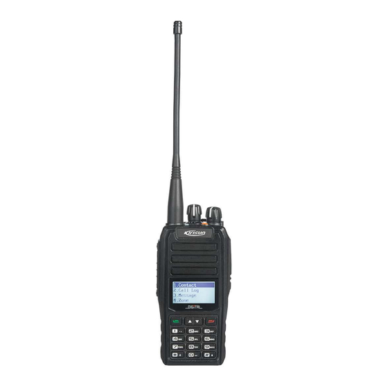
Page 5: External View And Functional Keys
FP560 Service Manual External View and Functional Keys 2.1. External View and Functional Keys Part Name Part Name PTT(PUSH-TO-TALK)Button Side Button 1(Programmable Press and hold the PTT button Button) and talk to the microphone to transmit; release it to listen. Menu Key Press the menu key and enter the Side Button 2(Programmable... -
Page 6: Programmable Button
FP560 Service Manual LCD Screen It indicates the operation status of Microphone the radio. Please see other chapters for more details. Up Key Down Key Digital Keyboard There are 12 keys in total. Press Delete Key these keys to enter the numbers and edit the text or new contact. -
Page 7: Led Indicator
FP560 Service Manual If there is CTCSS on the current analog channel, press the key and switch to carrier squelch mode to cancel the CTCSS feature; the voice Monitor Mementary will be output when the carrier is matched. Release the key to go back to the original status. -
Page 8: Principle Of Receiver (Rx)
FP560 Service Manual 450KHz MIXER IF SYSTEM ANT SW 51.65MHz 12.8MHz TCXO multiply CODEC This Radio applies twice frequency mixing method. The first intermediate-frequency is 51.65MHz. The second intermediate-frequency is 450kHz. The first local oscillation is generated by frequency synthesizer, and the second local oscillation is generated by the qcuadruple frequency of 12.8MHz. -
Page 9: Principle Of Transmitter (Tx)
FP560 Service Manual which passed the band-pass filter (BPF) consisting of two levels of LC to eliminate the unnecessary signals, then sent to the low noise amplifier (LNA) consisting of Q703 and its peripheral components for enlargement. After passing the band-pass filter (BPF) consisting of three levels of LC to further eliminate the unnecessary out-of-band signals, the output of LNA is then sent to the first frequency mixer (Q702). -
Page 10: Principle Of Frequency Synthesizer
FP560 Service Manual The modulated RF signal from VCO, being amplified by Q303、 Q304、 Q602、 Q603、 Q601, is sent to Q600 for power amplification. The grid bias of Q601 and Q600 is controlled by APC (Automatic Power Control) circuit. Change the grid bias voltage to easily control the output power strength of the transmitter. -
Page 11: Audio Processing Circuit
FP560 Service Manual programmable reference frequency divider in IC300 to become the 5kHz or 6.25kHz (controlled by MCU, according to the setting channel) reference frequency . The oscillation frequency from VCO, being amplified by the two-time frequency multiplier circuit, is sent to IC300 for comparison with reference frequency after being divided by the programmable frequency divider, and the error signal is then generated to change the oscillation frequency of VCO after filtered by the low pass filter. -
Page 12: Power Supply
FP560 Service Manual The emergency alert tone is not controlled by volume. 3.7. Power Supply This radio applies 7.4V battery. The transmitter power amplifier circuit (Q601, Q600) and receiver audio processor (U800) directly use the battery for power supply with other circuits using the voltage stabilized 5V for power supply. - Page 13 FP560 Service Manual data. CTCSS/DCS Signal Encoding and Decoding: The CTCSS/DCS signal generated by MCU is sent separately to VCO and TCXO for modulation. The CTCSS/DCS signal from the receiver is sent to MCU for decoding. The MCU identifies whether the CTCSS/DCS signal of the radio is the same as the receiving signal so as to turn on the speaker.
-
Page 14: Semiconductor Device Description
FP560 Service Manual Chart 3-2 DCS Coding Chart 3.9. Semiconductor Device Description MCU Description Chart 3-3 Microprocessor (M30620) Port Description Pin No. Port Name Input/ Function output PCTV D/A Output Receiver sensitivity adjusting voltage output/power control (V) DTMF D/A Output DTMF/Tone output, beep output HSDI Tone decoding input... - Page 15 FP560 Service Manual CTCSS/DCS CTCSS/DCS output TDATA AK2346 MSK data transmission output StCtrl Side tone volume control pin DI/O AK2346 data input output control pin CTCSSVCO CTCSS/DCS output VCO (PWM) AK2346 IO control Power control (U) CTCSSTCXO CTCSS/DCS outputs (PWM) TXD1 output RXD1 input APC SW...
- Page 16 FP560 Service Manual OPT S1 Earphone check OPT S2 External PTT MAN DN MAN DOWN input PIO3 Extension PIO2 Extension PIO1 Extension PINT Extension Top key PTT key Side key 2 Side key 1 SP SW Speaker switch MIC SW MIC switch R LED LED red switch...
- Page 17 FP560 Service Manual IC700 GT3136 Receiver 2nd local oscillation, 2nd IF amplification, amplitude limit, demodulation, noise amplification IC204 NJM2902 Receiver demodulated signal is amplified, filter M30620 IC200 AT24C512C E2PROM, saving channel frequency data, feature setting parameters and adjustment status parameters. U800 TDA2822 Receiver audio power amplification...
-
Page 18: Function Description And Parameter Settings
FP560 Service Manual D604 HZU5ALL APC output limited voltage diode D600,D601 HVC131 Transmitter antenna switch diode D602,D603 D704,D705,D HVC355B RX band pass filter varactor diode 706,D707 D708 D701 RB706F Commutation diode Function Description and Parameter Settings 4.1. Time-out Timer This feature prevents the user from long occupation on the channel. If the transmitting period exceeds the dealer’s preprogrammed time, the radio stops transmitting and rings alert tone. -
Page 19: Emergency
QT/DQT, and auto scan feature may be reset according to different requirements of the customers. Hence, Kirisun designed a Chinese/English FP520 programming software with friendly interface, easy operation and clear visual display to complete the parameter settings for FP520. -
Page 20: Assemble And Disassemble Instructions
FP560 Service Manual B. As Figure 4-1 shows, using the FP520 programming cable to connects the computer with the radio Note: During the connection, ① make sure the computer is off. ② make sure the radio is off. Figure 4-2 FP560 programming Computer Radio... -
Page 21: Attaching The Antenna
FP560 Service Manual ② shows, and take out the battery as ③ shows; if the belt clip is attached, please press it as ④ shows and detach the battery downwards. Figure 5-3 Notes: • Do not short circuit the battery terminals or abandon the battery into fire. •... -
Page 22: Attaching And Detaching The Earphone
FP560 Service Manual Figure 5-5 5.4. Attaching and Detaching the Earphone When the earphone is needed, open the earphone cover on the upper right side of the radio, and put the earphone plug into the interface. Figure 5-6 5.5. Separating the Front Cover from the Chassis 1. -
Page 23: Separating The Pcb Board From The Chassis
FP560 Service Manual 5.6. Separating the PCB Board from the Chassis 1. Remove the potentiometer waterproof pad on top; 2. Remove the earphone waterproof plug; 3. Remove the screws on the PCB mainboard; 4. Remove the two screws on the side PTT PCB; 5. -
Page 24: Exploded View
FP560 Service Manual 5.7. Exploded View Part Number Description Quantity Remark FP560 digital Silicone gel+plastic key+plastic 7MHR-4091-01A-W0 keypad frame PT560 earphone 7MHP-7208-06A-W0 ABS+PC;black cover plug PT560 earphone 7MHP-7208-07A-W0 TPU;black cover board FP560 lens 7MHJ-4091-01A-W double-sided 3M9448 adhesive tape 7MBP-4091-01A-WC FP560 lens PC, silk print black frame φ7 mic waterproof cloth,diameter φ7mm,... - Page 25 FP560 Service Manual 7MHP-4083-01A-W0 FP560 front shell ABS+PC; black; silk print PT560 LOGO T=0.3mm PC sticker PT560 emrgency 7MHR-7208-05A-W3 Silicone, orange button; PT560 guide 7MHR-7208-04A-W9 Silicone; transparent milk white beam φ36 speaker 7GCB-360001-W0 Black wanterproof cloth wanterproof net ∅ 40 speaker 4SS7-4050-016-100 MM4050-1638,16Ω,1W PT560 side...
- Page 26 FP560 Service Manual PT560 main unit 7MHP-4091-02A-W0 ABS,+PC black top cover KBJ-09 belt clip Stainless steel ;(SUS304),1.00THK, 7MJS-7013-01B-N bracket bright nickel-plated KBJ-09 belt clip 7MJS-7013-02A-W torsional spring KBJ-09 belt clip 7MJS-7013-03A-N spin axis M2.5*8 cross 7SMF-025080M-SZYB round flat head For fixing belt clip machine screw 7MJP-4026-01A-W0 KBJ-15 belt clip...
-
Page 27: Adjustment
FP560 Service Manual round flat machine screw Black and white screen 6MD7-F04932 FP560 LCD ,128*64 FP560 LCD 7GCM-411294-J PRON, 41.1*29.4mm sponge pad FP560 keypad 7MHJ-4091-01A-W double-sided 3M9448 adhesive tape FP560 digital 7MHR-4091-01A-W0 Thickness 0.6mm keypad PCB FP560 digital SUS301,Φ5mm Metal Dome 7MHS-4091-02A-W keypad metal dome... -
Page 28: Computer Adjustment Method
FP560 Service Manual 6.1.3. Computer Adjustment Method VCO Part The radio is receiving: a) The channel is on the receiving high frequency, adjust C335 and test T300, the spot voltage is 3.6 ± 0.1V. b) The channel is on the receiving low frequency, test T300, the spot voltage>0.6V The radio is transmitting :... -
Page 29: Radio Test
FP560 Service Manual [transmitting low voltage], click OK when the digits are stabilized. RX Part 1). Receiver Pass Band a. Program the spectrum analyzer, and test the receiver pass band at the test point with a high frequency probe. b. Under the computer mode [receiving sensitivity] (five frequencies), adjust the receiver pass band to the corresponding center frequency. -
Page 30: Major Specifications
FP560 Service Manual 3. The maximum frequency deviation: 1.8kHz---2.5kHz 4. TX distortion: <=5% 5. QT/DQT frequency deviation: 0.3---0.5kHz with fine wave form. 6. TX frequency deviation: Nominal frequency +/-500Hz 7.DTMF frequency deviation: 1.5~2.0 kHz 8. FFSK frequency deviation: 1050Hz+/-50 9. Under voltage Indication: The voltage is 6.6V, the indicator glows red when PTT is pressed; no TX power. - Page 31 FP560 Service Manual RX Part ≤0.25μV Sensitivity (12dB SINAD) ≤0.18uV Squelch-On Sensitivity ≤-35dB Receiver Residual Output Modulated RX Bandwidth ±3.5kHz ≥50dB Adjacent Channel Selectivity ≥65dB Intermodulation Interference Rejection ≥70dB Spurious Response Rejection 1.3W, BTL@distortion≤10%, 16Ω Audio Output Power ≤400mA RX Consumption Current TX Part Tx Power 4.0W/1.0W@7.5V DC...
-
Page 32: Maintenance And Test Equipment
FP560 Service Manual Maintenance and Test Equipment During the service and test, the following equipment and apparatus are needed. Equipment Specification Standard Signal Generator Frequency Range: 400- 470MHz Modulation: FM and External Modulation Output: -127dBm/0.1uv or ≥-47dBm/1mv 50Ω Power Meter Input Impedance: Operation Frequency: 400 - 470MHz... -
Page 33: Kbc-51 Charger
FP560 Service Manual KBC-51 Charger 9.1. The Operational Conditions and Basic Specification of Charger a) Battery Specification:Li-ion(2*3.7V),battery capacity (1~2.4AH). b)Power Adaptor Specification: DC 11V~16V,500~1500mA power adaptor,standard voltage is 12V. c) No-load Input Current: ≤ 15mA d) Precharged Current: 200 mA±40 mA e) Precharged Time Limit: 15Min f) Constant Current Charging Current:800mA±40 mA g) Maximum Li-ion Charging Voltage:8.32~8.42V. -
Page 34: Troubleshooting
FP560 Service Manual LED lights red: Charging LED lights green: Full battery LED lights yellow: Abnormal charging Troubleshooting Problem Cause and Solution A.The battery pack may be out of power. Please charge it or change to a new one, then try again. B.Power switch failure. - Page 35 FP560 Service Manual A.The antenna is in poor contact,please fasten it again. B.Low sensitivity,adjust the parameter in the “test mode”. C.The high-mu tube Q703 is broken, please change it. No Signal D.The squelch level is too high to turn it on, please adjust the squelch level.
-
Page 36: Appendix 1 Abbreviation
FP560 Service Manual Appendix 1 Abbreviation Amplify, Amplifier Antenna Automatic Power Control Band Pass Filter CTCSS Continuous Tone Control Squelch System Digital Code Squelch DEMOD Demodulation E2PROM Electrically Erasable Programmable Read-Only Memory High Pass Filter Instantaneous Deviation Control Intermediate Frequency Light-Emitting Diode Low Noise Amplifier Low Pass Filter... -
Page 37: Appendix 2 Accessory List
FP560 Service Manual Appendix 2 Accessory List Accesoory Quantity Antenna Adapter Belt Clip Intelligent Charger Strap Battery User Guide Appendix 3 List 1 Spare Pare List (Electronic Section 400-470MHz) Quanti Part Number Item Name Specification Plug-in Unit Postion 400-470MHz,4W, FP560-02 charger KBC-51 FP560-02 main 400-470MHz,... - Page 38 FP560 Service Manual SMD switch diode 1DS1-HVC131 HVC131(P1),1608 D600 D601 tube 1DS1-DA2S10100 SMD switch diode DA2S10100L D309 D310 D709 tube Schottky diode SMD switch diode 1DS1-RB706F-40 RB706F-40,SOT-3 D701 tube SMD varactor 1DV1-1SV278 1SV278(T1) D304 diode tube D300 D301 D302 D303 SMD varactor D305 D306 D307 D308 1DV1-HVC376B...
- Page 39 FP560 Service Manual pb-free Regulated voltage 1IS1-XC6204B502 SMD regulated integrated IC100 voltage IC 5V,SOT-23-5 1TF1-2SK1824 SMD FET 2SK1824(B1) Q606 Q6 Q704 1TF1-2SK508NV- SMD FET Q302 Q307 SMD dual grid 1TF1-3SK318 3SK318(YB-) Q702 Q703 FET. 1TF1-RD01MUS2 SMD FET Q601 1TF1-RD07MUS2 RD07MUS2B,,p SMD FET Q600 b-free...
- Page 40 FP560 Service Manual -220J capacitor ,C0G 2CC1-10-C0G500 flake multi-layer 1005,27P±5%,50V C313 -270J capacitor ,C0G 2CC1-10-C0G500 flake multi-layer 1005,2P±0.25P,50 C302,C731 -2R0C capacitor V,C0G 2CC1-10-C0G500 flake multi-layer 1005,33P±5%,50V C754,C355,C612 -330J capacitor ,C0G 2CC1-10-C0G500 flake multi-layer 1005,3P±0.25P,50 C702 C328 C741 C725 -3R0C capacitor V,C0G C724 2CC1-10-C0G500...
- Page 41 FP560 Service Manual 182K capacitor 50V,X7R C42 C43 C45 C58 C59 C102 C104 C105 C107 C108 C110 C113 C207 C208 C221 C222 C230 C231 C232 C233 C300 2CC1-10-X7R500- flake multi-layer 1005,470P±10%,5 C301 C316 C320 C336 471K capacitor 0V,X7R C337 C338 C339 C53 C52 C755 C756 C757 C758 C760 C762 C763 C803 C804 C809 C810 C813...
- Page 42 FP560 Service Manual 3216,0.1μF±20%, 2CT1-TS32-350-R SMD tantalum 35V,TS series C358 capacitor (level A) 3216,15μF±20%,6 2CT1-TS32-6R3-1 SMD tantalum .3V,TS series C1 C376 capacitor (level A) 2CT1-TS35-6R3-1 SMD tantalum C-TAN,100uF,20 C805 capacitor %,SIZE-B,6.3V Wire diameter φ0.40, internal 2LH1-R401R5-R0 L600 L601 L603 L709 diameter φ1.5,3 SMD chip inductor 3-05...
- Page 43 FP560 Service Manual LG1608B82NJ) 1608,0.22μH±5%( LG HK 2LL1-16-R22J lamination inductor L306 L319 L324,L303 1608R22J-T/MLG 1608B220N) 1608,560nH±10%( 2LL1-16-R56K lamination inductor L300 MLF1608DR56K) 1608,18nH±5%,ce ramic 2LW1-16UC-180J SMD wire inductor L301 L700 L304 chip(C1608CB-18 1608,180nH±5%, 2LW1-16UC-181J SMD wire inductor ceramic chip L321 (C1608CB-R18J) 1608,68nH±5%, 2LW1-16UC-680J SMD wire inductor...
- Page 44 FP560 Service Manual R39 R40 R107 R143 R604 R616 R824 C73 C74 R51 R231 R244 R300 R308 1005,10Ω±5% 2RS1-10-100J flake resistor R324 1005,100Ω±5% 2RS1-10-101J flake resistor R321 R703 R248 R823 R15 R38 R106 R197 R198 R229 R236 R237 2RS1-10-102J flake resistor 1005,1K±5% R238 R239 R254 R255 R301 R304 R341...
- Page 45 FP560 Service Manual 1005,47Ω±5% 2RS1-10-470J flake resistor R600 1005,470Ω±5% 2RS1-10-471J flake resistor R11 R814 R811 R706 R322 R343 R406 2RS1-10-472J flake resistor 1005,4.7K±5% R407 R700 R22 R23 R24 R27,R29 R30 2RS1-10-473J flake resistor 1005,47K±5% R31 R240 R241 R242 R243 R601 R608 R613 R61 R62 2RS1-10-474J flake resistor 1005,470K±5%...
- Page 46 FP560 Service Manual +85℃,2.5*2.0*0.8 NT5032SA/NT503 SMD temperature 5OT1-12R8-CEC3 2SC,12.8MHz±2.5 supplemented X300 -0503 PPm,5.0*3.2*1.6m crysral oscillator 9.8304MHz±30PP M,±50PPM,16P,-4 5XC1-9R8-MPL20 SMD crystal 0℃ X200 -0503 harmonic oscillator to+80℃,NX5032G FP520U-MAIN-14 0106.PCB;1.0MM FP560 ;47X101.5MM; 6PM7-4083-HMB Mainboard PCB UHFmainborad FR-4,four layers; pb-free 7MHP-7042-12A- 3600 568 567 battry connector 7800 Single phase...
- Page 47 FP560 Service Manual IC,XC6228D122V R-G,SOT-25J,5PI N, ,pb-free 3216,0.33μF±20% 2CT1-TS32-350-R SMD tantalum ,35V,TS series(A C360 capacitor level) SMD varactor HVC350B(B0),SO 1DV1-HVC350B D702 diode D523 1005,330Ω±5% 2RS1-10-331J flake resistor R713、R714 R330 R247 2CC1-10-C0G500 Flake multi-layer 1005,7P±0.25P,50 C746 -7R0C capacitor V,C0G 2RS1-10-123J flake resistor 1005,12K±5% C823 1005,510Ω±5%...
- Page 48 FP560 Service Manual 2CC1-10-X7R500- flake multi-layer 1005,470P±10%,5 C105 C107 471K capacitor 0V,X7R Digital triode 1TT1-DTC144EE SMD triode DTC144EE(26),S Q1 Q201 OT323 2CC1-20-Y5V160- flake multi-layer 2012,10uF+80%/- C106 106Z capacitor 20%,16V,Y5V 3CF1-BL112-30R SMD FFC/FPC Interval 0.5mm,30 connector chip Interval 3CF1-BL112-16R SMD FFC/FPC 0.5mm,16chip,BL1 connector 12-16RL,...
- Page 49 FP560 Service Manual ZHT-B crossthick-headed iron,Φ2.6mm*10m self-tapping screw KBC-51 charging 6SS2-4083-CMA nucleus board suite KBC-51chargig 0SS2-4083-CMA nucleus board plug-in units plug-in unit 1DR3-P6KE30A commutation P6KE30A,DO15 diode plug-in unit 1IS3-TL431AA specialized IC TL431AA,TO92 charger IC 8*12,100μF±20%, plug-in unit 35V,GM[replaced 2CE3-GM350-101 Aluminum M0812 electrolysis 2CE3-GM350-101...
- Page 50 FP560 Service Manual OT23,PNP( AO3401A,SOT-23 , can be replaced 1TT1-AO3401A SMD triode 1TT3-2SB772SL S9013LT1,SOT-2 1TT1-S9013LT1 SMD triode 3,NPN 2CC1-16-X7R500- flake multi-layer 1608,1000P±10%, 102K capacitor 50V,X7R 2CC1-16-Y5V250- flake multi-layer 1608,100nF+80%, 104Z capacitor 25V,Y5V SMD precise 2RE1-16-1503 1608,150K±1% resistor SMD precise 2RE1-16-2402 1608,24K±1% resistor SMD precise...
-
Page 51: List 2 Spare Pare List (Electronic Section 136-174Mhz)
FP560 Service Manual List 2 Spare Pare List (Electronic Section 136-174MHz) Quan Part Number Item Name Specification Plug-in Unit Postion tity FP520-01 FP520-01, 6SS1-4085-HMB main board SMD 136-174MHz. FP520-01mainb FP520-01mainboard 0SS1-4085-HMD oard SMD SMD,136-174MHz. FP520V-MAIN-1401 ; FP520 06.PCB;1.0MM 6PM7-4085-HMB FP520 mainboard 47X101.5MM,FR-4;f our-layers,pb-free... - Page 52 FP560 Service Manual 25Q32BVSSIG,8PIN 1IM1-25X32VSIG memorizer , IC ,SOIC,pb-free 1IM1-AT24C512 SMD memorizer AT24C512C, pb-free IC200 1IS1-GT3136 SMD IC GT3136,SSOP16 IC700 1IS1-MB15E03S MB15E03SL,TSSO SMD PLL IC IC300 P-16 1IS1-PST9124N Reset SMD reset IC IC202 IC,PST9124NR , Digital baseband SCT3252PS 1IS1-SCT3252PS processor chip LQFP100,pb-free ,...
- Page 53 FP560 Service Manual 2SC5108-Y(MC),NP Q300 Q301 Q303 Q304 Q602 1TT1-2SC5108-Y SMD triode Q701 Digital triode 1TT1-DTA143TE SMD triode DTA143TE(93),SOT Q305 Q306 Q604 Digital triode Q2 Q4 Q101 Q103 Q200 1TT1-DTC144EE SMD triode DTC144EE(26),SOT Q201 Q605 Q801 Q804 Q806 Q707 1TT1-FMMT717T FMMT717A,PNP,S SMD triode Q800...
- Page 54 FP560 Service Manual 0-4R7C capacitor V,C0G 2CC1-10-C0G50 flake multi-layer 1005,5P±0.25P,50V, C621 C314 C315 C324 C723 0-5R0C capacitor 2CC1-10-C0G50 flake multi-layer 1005,82P±5%,50V, C759 0-820J capacitor 2CC1-10-C0G50 flake multi-layer 1005,8P±0.5P,50V, C703 0-8R0D capacitor 2CC1-10-C0G50 flake multi-layer 1005,9P±0.5P,50V, C702 0-9R0D capacitor 2CC1-10-C0G50 flake multi-layer 1005,0.5P±0.1P,50V C325 C343 C357 0-R50B...
- Page 55 FP560 Service Manual 2CC1-16-C0G50 flake multi-layer 1608,10P±0.5P,50V, C501 C508 C509 C514 0-100D capacitor 2CC1-16-C0G50 flake multi-layer 1608,11P±5%,50V, C504 0-110J capacitor 2CC1-16-C0G50 flake multi-layer 1608,12P±5%,50V, C503 0-120J capacitor 2CC1-16-C0G50 flake multi-layer 1608,13P±5%,50V, C516 0-130J capacitor 2CC1-16-C0G50 flake multi-layer 1608,18P±5%,50V, C515 0-180J capacitor 2CC1-16-C0G50 flake multi-layer...
- Page 56 FP560 Service Manual diameterφ1.0, circles, high pin Wire diameter φ0.30, 2LH1-R301R5-R internal SMD inductor L505,L502,L503 07-05 diameter,1.5 circles, high pin Wire diameter φ0.40, internal 2LH1-R401R5-R φ1.5,3 SMD inductor diameter, L9 L500 03-05 circles, pin height 0.5mm Wire diameter, φ0.40, 2LH1-R401R5-L0 internal SMD inductor L607...
- Page 57 FP560 Service Manual (C1608CB-18NJ) 2012,22nH±2%, 2LW1-20UC-220 wire ceramic core L308 inductor (C2012CB-22NG) 2012,220nH±5%, 2LW1-20UC-221 wire ceramic core L608 inductor (LQN21AR22J/LQW 2BHNR22J03L) 2012,39nH±2%, 2LW1-20UC-390 wire ceramic core L322 inductor (C2012C-39NG) 2012,47nH±5%, 2LW1-20UC-470 wire ceramic core L714 inductor (C2012C-47NJ) 2012,68nH±5%, 2LW1-20UC-680 wire ceramic core inductor...
- Page 58 FP560 Service Manual R239 R254 R255 R301 R304 R341 R602 R822 R823 R331 R52 R53 R57 R813 R809 R806 R8 R33 R34 R35 R36 R37 R38 R43 R100 R103 R250 R251 2RS1-10-103J flake resistor 1005,10K±5% R252 R327 R337 R338 R339 R340 R344 R700 R718 R801 R815 R816 R32...
- Page 59 FP560 Service Manual 2RS1-10-474J flake resistor 1005,470K±5% R716 R805 2RS1-10-512J flake resistor 1005,5.1K±5% R199 R200 R218 1005,56Ω±5% 2RS1-10-560J flake resistor R710,R722 2RS1-10-563J flake resistor 1005,56K±5% R629 2RS1-10-564J flake resistor 1005,560K±5% R712 2RS1-10-823J flake resistor 1005,82K±5% R705 R723 1608,0Ω 2RS1-16-000O flake resistor L100 L102 L103 L708 2RS1-16-153J flake resistor...
- Page 60 FP560 Service Manual ±50PPM,16P,-40 ℃ 0-0503 oscillator to+80℃,NX5032GA 1DR1-1SR154-40 commutation 1SR154-400,4532 D100 diode Power 1IS1-XC6228D12 SMD specialized IC,XC6228D122VR- IC102 G,SOT-25J,5PIN,pb -free lamination 1608,27nH±5%(ML 2LL1-16-27NJ L604 inductor G1608B27NJ) 2RS1-10-224J flake resistor 1005,220K±5% R728 2CC1-10-C0G50 flake multi-layer 1005,39P±5%,50V, C734 0-390J capacitor 2CC1-10-C0G50 flake multi-layer 1005,7P±0.5P,50V, C333 C331...
- Page 61 FP560 Service Manual 2CC1-10-X7R500 flake multi-layer 1005,1000P±10%,5 -102K capacitor 0V,X7R FP520-01 FP520-01,136-174M 6SS1-4085-HMB mainboard SMD FP520-01 FP520-01 0SS1-4085-HMD mainboard mainboard SMD SMD,136-174MHz. FP520V-MAIN-1401 ; FP520 06.PCB;1.0MM 6PM7-4085-HMB FP520- VHF mainboard PCB mainboard 47X101.5MM;FR-4; four layers, pb-free 7MHP-7042-12A- PT568 battery 3600 connector 7800 1DS1-DA2S1010...
- Page 62 FP560 Service Manual IC,PST9124NR Digital baseband , processor chip SCT3252PS 1IS1-SCT3252PS FP520 LQFP100,pb-free FP560 1IS1-SCT3252P Baseband chip SCT3252PN 1IM1-ST24 Vocoder ST24, 6.25K series 1 SMD specialized 1IS1-TDA2822 TDA2822 U800 1IS1-UPB1509G SMD specialized Frequency divider UPB1509GV,SSOP WM8758CB, 32-Pin CODEC chip for 1IS1-WM8758B QPN, FP520 FP560...
- Page 63 FP560 Service Manual 2CA1-TZVY2Z10 adjusted 2-10P,+100/-0%,NP C335 C371 0A110 capacitor 0±300PPm/℃ 2CC1-10-C0G50 flake multi-layer 1005,10P±0.5P,50V, C308 C309 C318 C321 C328 0-100D capacitor 2CC1-10-C0G50 flake multi-layer 1005,100P±5%,50V, C612 C765 C375 C643 0-101J capacitor C725 C751 2CC1-10-C0G50 flake multi-layer 1005,150P±5%,50V, C323 C718 C722 0-151J capacitor 2CC1-10-C0G50...
- Page 64 FP560 Service Manual 3-105K capacitor ,X5R C40 C10 C21 C22 C24 C25 C26 C27 C28 C32 C50 C51 C55 C56 C89 C91 C14 C23 2CC1-10-X7R160 flake multi-layer 1005,100nF±10%,1 C12 C39 C92 C100 C101 -104K capacitor 6V,X7R C111 C114 C224 C334 C345 C707 C715 C749 C764 C801 C808 C816 C818 C819 C822 C712...
- Page 65 FP560 Service Manual 0-330J capacitor 2CC1-16-C0G50 flake multi-layer 1608,5P±0.25P,50V, C365 0-5R0C capacitor 2CC1-16-C0G50 flake multi-layer 1608,68P±5%,50V, C66 C634 0-680J capacitor 2CC1-16-C0G50 flake multi-layer 1608,7P±0.5P,50V, C505 0-7R0D capacitor 2CC1-16-X7R500 flake multi-layer 1608,1000P±10%,5 C611 -102K capacitor 0V,X7R 2CC1-20-Y5V100 flake multi-layer 2012,330nF+80%/-2 C705 -334Z capacitor 0%,10V,Y5V...
- Page 66 FP560 Service Manual circles, high pin 1608,1μH±10%(MLF lamination 2LL1-16-1R0K L703 inductor 1608A1R0K) lamination 1608,22nH±5%(ML 2LL1-16-22NJ L610 inductor G1608B22NJ) lamination 1608,33nH±5%(ML 2LL1-16-33NJ L700 L301 inductor G1608B33NJ) lamination 1608,39nH±5%(ML 2LL1-16-39NJ L311 inductor G1608B39NJ) 1608,3.3μH±10%(M lamination 2LL1-16-3R3K LF1608A3R3K L309 L323 inductor TA00) lamination 1608,82nH±5%(ML 2LL1-16-82NJ L313 L609...
- Page 67 FP560 Service Manual 2012,68nH±5%, 2LW1-20UC-680 wire ceramic chip inductor (C2012C-68NJ) 2012,56nH±5%, 2LW1-20UC-560 wire ceramic chip L706 L709 L713 inductor (C2012C-56NJ) 2520,1μH±5%, 2LW1-25UC-102 wire ceramic chip L606 inductor (FHW1008UC1R0J) 2520,10μH±5%, 2LW1-25UC-103 wire ceramic chip L305 inductor (FLM2520-100J) 2520,330nH±10%, 2LW1-25UC-331 wire ceramic chip L704 inductor...
- Page 68 FP560 Service Manual 2RS1-10-153J flake resistor 1005,15K±5% 2RS1-10-154J flake resistor 1005,150K±5% R303 R314 1005,180Ω±5% 2RS1-10-181J flake resistor R310 2RS1-10-182J flake resistor 1005,1.8K±5% R44 R817 2RS1-10-184J flake resistor 1005,180K±5% R727 2RS1-10-204J flake resistor 1005,200K±5% R302 1005,22Ω±5% 2RS1-10-220J flake resistor R305 R611 R715 R804 1005,220Ω±5% 2RS1-10-221J flake resistor...
- Page 69 FP560 Service Manual 003,3216,3A/32V 3ST1-SKRTLBE0 SKRTLBE010,4.5*3. SMD tact switch 55*3.3mm(ALPS) 1608,red 4PE1-16-F2 SMD LED light,19-21SUR/S53 D202 0-A2/TR8 1608,green 4PE1-16-F5 SMD LED D203 light,H19-213SYGC DSF753SDF,51.65 5FC1-D51606GQ SMD crystal filter MHz±3KHz/5dB,7.0* 1-0705 for FP520 5.0*1.3 1608,BLM11A221S 5FE1-BLM11A22 FB1 FB7 FB8 FB9 FB12 PT/BLM18AG221S( 1SPT suppressed filter...
- Page 70 FP560 Service Manual 1005,680Ω±5% 2RS1-10-681J flake resistor R329 2CC1-20-Y5V160 flake multi-layer 2012,1uF+80%/-20 C36 C218 -105Z capacitor %,16V,Y5V 2CC1-16-C0G50 flake multi-layer 1608,20P±5%,50V, C613 0-200J capacitor 2CC1-16-C0G50 flake multi-layer 1608,120P±5%,50V, C610 0-121J capacitor 1IP1-0FP520-R0 CPU,M16C-M3062L burning chip FGPGP,pb-free 1IP1-M16CM306 CPU,M16C-M3062L SMD CPU 2LFGPGP FGPGP,FLASH 9FSO-6500V333...
- Page 71 FP560 Service Manual 0603, white, height 4PE1-16-F9-A SMD LED D1 D2 D3 D4 D5 D205 0.4mm 1608,0Ω 2RS1-16-000O flake resistor L102 1005,10Ω±5% 2RS1-10-100J flake resistor R1 R2 R244 1005,220Ω±5% 2RS1-10-221J flake resistor R250 1005,22Ω±5% 2RS1-10-220J flake resistor FP560-key-140224. FP560 SIZE:35X41mm 6PD7-4091-HKB board PCB thickness:0.6mm...
- Page 72 FP560 Service Manual plug-in unit 1IS3-TL431AA specialized TL431AA,TO92 charger IC plug-in unit 8*12,100μF±20%,35 aluminum 2CE3-GM350-10 V,GM type electrolysis 1M0812 [2CE3-GM350-101M capacitor 0611] charger plug-in unit aluminum 5×11,47μF±20%,25 2CE3-GM250-47 electrolysis 0M0511 V,GM type capacitor charger plug-in unit aluminum 10×16,470μF±20%, 2CE3-GM350-47 electrolysis 1M1016 35V,GM type capacitor...
-
Page 73: List 3 Material List (Structure Material)
FP560 Service Manual 1TT3-2SB772SL S9013LT1,SOT-23, 1TT1-S9013LT1 SMD triode 2CC1-16-X7R500 flake multi-layer 1608,1000P±10%,5 -102K capacitor 0V,X7R 2CC1-16-Y5V250 flake multi-layer 1608,100nF+80%,2 -104Z capacitor 5V,Y5V precise 2RE1-16-1503 1608,150K±1% resistor precise 2RE1-16-2402 1608,24K±1% resistor precise 2RE1-16-3601 1608,3.6K±1% resistor precise 2RE1-16-5102 1608,51K±1% resistor precise 2RE1-16-8201 1608,8.2K±1% resistor 1608,10Ω±5%... - Page 74 FP560 Service Manual FP560 major Silicone gel; black; polished; 7MHR-7208-01A-W0 waterproof ring pb-free FP560 earphone 7MHP-4083-02A-W0 socket waterproof TPU; black; pb-free plug FP560 top channel 7MHR-7208-02A-W0 Silicone gel; black; pb-free waterproof ring thermally conductive Silicone gel, black,3*6*9mm. 7MHR-7042-06B-W0 silicone gel pad pb-free FP560 aluminum 7MHL-4083-01A-W...
- Page 75 FP560 Service Manual Balck& white screen , 128*64 , 6MD7-F04932 FP560 LCD module pb-free ND036GM13924,16Ω,1W,Φ36*H 4SS7-3605-016-100 FP560 36mm speaker 5.0, pb-free φ32 speaker waterproof Speaker waterproof φ32mm*thickness 7GCB-320001-W0A net,diameter 0.1mm 7MBP-4091-01A-W0 FP560 front shell PC365; black; silk print; pb-free Silicone gel , 65 degrees , 7MHP-4091-01A-W FP560 guide beam transparent white,pb-free...
- Page 76 FP560 Service Manual dome dome; pb-free Flexible connecting Interval 0.5mm,30P, wire length 3WF7-05030-500C4 wire 50mm DP770 belt clip,PC+ABS,black, 6SS3-BJ4026-A belt clip pb-free DP770 belt clip,PC+ABS, black, 7MJP-4026-01A-W0 belt clip pb-free Stainless 7MJS-7013-01B-N belt clip bracket steel(SUS304),1.00THK, nickel plated,pb-free belt clip torsional φ1.00 Stainless steel, pb-free 7MJS-7013-02A-W spring...
-
Page 77: Figure 1 Fp560-01 Mainboard Schematic Diagram (136-174Mhz)
FP560 Service Manual Figure 1 FP560-01 Mainboard Schematic Diagram (136-174MHz) Q100 KTA1298 XC6204B502MR C100 R100 R101 2.2K ST2301 Q101 DTC144EE IC100 XC6204B502MR L100 Q102 KTA1298 C102 C101 R103 C103 C104 R102 10UF 2.2K Q103 DTC144EE Q1 KTA1298 2.2K DTC144EE IC101... - Page 78 FP560 Service Manual TX_SW RX_SW AFCO_2 AFCO_1 C_CLK C_BUSY C_EPN PC/TV XOUT C_CE R229 SCT3252MOD 33NF 33NF C225 27P GREEN_LED RED_LED C227 C226 R231 SHIFT 0Ω SAVE Q204 L203 BLM11A601S X200 9.8304M S_SI INT0 S_SCK INT0 S_SCK PLLBYPASS VC_12.288M PLLBYPASS TP10 PLLSEL2 S_SO...
- Page 79 FP560 Service Manual NC_1 NC_5 12.288MHz V D D SCL_CODEC V S S O U T 100K VDDIO33 MCLK12M88 SDA_CODEC VDDIO33 VDDIO33 0.1uF VDDIO33 VDDIO33 TRSTN 270p VDDIO33 VDDIO33 R1 0R VDDIO33 VDDIO33 HOLDA SCT3252MOD VDDIO33 VDDIO33 PIO0 SCL_CODEC VDDIO33 PIO1 SDA_CODEC VDDIO33...
- Page 80 FP560 Service Manual HOLE HOLE HOLE HOLE H o l e H o l e H o l e H o l e H801 H803 H804 H805 HOLE HOLE HOLE HOLE HOLE H o l e H o l e H o l e H o l e H o l e...
- Page 81 FP560 Service Manual R300 R301 L300 C300 560nH L301 C301 33nH R302 200K C302 C304 102 C305 Q301 R303 Q300 C306 R304 2ND_LOCAL 2SC5108 2SC5108 150K C307 C308 L304 C309 C311 C313 C314 18nH C315 R305 C316 R306 C319 C318 10P 10UF D300 R309...
- Page 82 FP560 Service Manual C503 C504 C505 L500 C610 D600 C611 Q600 HVC131 0.4*1.5*3T 0.3*1.5*5T 0.4*1.5*3T L502 L501 L503 1000P RD07MUS2B 0.3*1.0*7T 0.4*1.5*7T 0.4*1.5*7T C508 L604 C612 TO ANT C509 100P 27nH D601 HVC131 C619 R600 D402 C621 R601 L610 R604 Q601 L609 C620...
- Page 83 FP560 Service Manual C700 4P D700 L700 33nH HSC277 FIRST_LOCAL C701 C702 C703 450B 10NF C704 C706 C707 RF_RX 1.8k R702 Q700 C710 BUSY 2SC4617 R704 330K L701 R701 C712 C708 68NH 120K D701 C705 R703 L702 0.33uF C714 R705 C711 RB706F C713...
- Page 84 FP560 Service Manual Q800 C801 FMMT717 C800 C802 10UF R801 R800 2.2K AFCO_1 Q801 DTC144EE C803 R802 NC R55 NC J800 C805 R61 47K R803 T D A 2 8 2 2 SPK_JACK 47uF/10V C806 Q802 ST2302 2SK1824 10UF N F 2 G N D C804 R804...
-
Page 85: Figure 2 Fp560-01 Top Pcb Position Mark Diagram (136-174Mhz)
FP560 Service Manual Figure 2 FP560-01 Top PCB Position Mark Diagram (136-174MHz) Page 82 of 96... -
Page 86: Figure 3 Fp560-01 Bottom Pcb Position Mark Diagram (136-174Mhz)
FP560 Service Manual Figure 3 FP560-01 Bottom PCB Position Mark Diagram (136-174MHz) Page 83 of 96... -
Page 87: Figure 4 Fp560-02 Mainboard Schematic Diagram (400-470Mhz)
FP560 Service Manual Figure 4 FP560-02 Mainboard Schematic Diagram (400-470MHz) Q100 KTA1298 ST2301 C100 R100 R101 2.2K Q101 DTC144EE L100 Q102 KTA1298 C102 C101 R103 C104 C103 R102 10uF 2.2K IC100 Q103 XC6204B502MR DTC144EE Q1 KTA1298 2.2K DTC144EE IC101 XC6204B332MR L102 C105 C111... - Page 88 FP560 Service Manual TX_SW RX_SW AFCO_2 AFCO_1 C_CLK C_BUSY 15K R26 C_EPN PC/TV XOUT C_CE R229 SCT3252MOD C225 22P GREEN_LED RED_LED C227 C226 R231 SHIFT SAVE Q204 L203 BLM11A601S X200 9.8304M S_SI INT0 S_SCK INT0 S_SCK PLLBYPASS VC_12.288M PLLBYPASS TP10 PLLSEL2 S_SO PLLSEL2...
- Page 89 FP560 Service Manual VDDIO33 VDDIO33 VDDIO33 12.288MHz VDDIO33 VDDIO33 TRSTN V D D VDDIO33 NC_1 VDDIO33 NC_5 VDDIO33 V S S O U T 100K SCL_CODEC VDDIO33 HOLDA SCT3252MOD MCLK12M88 VDDIO33 VDDIO33 PIO0 SCL_CODEC VDDIO33 PIO1 SDA_CODEC SDA_CODEC VDDIO33 PIO2/VSS VDDIO33 PIO3 PIO3...
- Page 90 FP560 Service Manual LAMP LAMP 3.3V 3.3V FP560_KEY_CON_MAINBOARD /CS1 /CS1 /RST /RST SCL/D6 SCL/D6 SI/D7 SI/D7 HOLE HOLE HOLE HOLE HOLE HOLE HOLE HOLE HOLE H o l e H o l e H o l e H o l e H o l e H o l e H o l e...
- Page 91 FP560 Service Manual R300 R301 L300 C300 560nH L301 C301 18nH R302 200K C302 C305 C304 102 Q301 R303 Q300 C306 R304 2ND_LOCAL 2SC5108 2SC5108 150K C307 C308 L304 C309 C313 C314 C311 18nH C315 R305 C316 R306 C319 C318 10P 10uF R309 270R...
- Page 92 FP560 Service Manual C603 C604 C605 1.5P 3.5P C610 D600 C611 Q600 HVC131 L600 2T L601 3T L602 4T L603 3T RD07 C612 L604 L605 TO ANT 3.9nH D601 HVC131 C619 D402 C621 R601 L609 C620 L610 R604 Q601 C618 R603 R606 L608...
- Page 93 FP560 Service Manual C700 D700 L700 HSC277 18nH FIRST_LOCAL C701 C702 C703 450B C704 D701 C705 RB706F C707 RF_RX R702 Q700 C710 BUSY 2SC4617 R704 330K L701 R701 C712 C708 68nH 100K C706 R703 L702 C714 R705 C713 100R C711 102 R706 C717 R708...
- Page 94 FP560 Service Manual Q800 C801 FMMT717 C800 C802 10uF R801 R800 2.2K AFCO_1 Q801 DTC144EE C803 R802 NC J800 C805 R803 SPK_JACK 100uF/6.3V C806 Q802 ST2302 10uF C804 2SK1824 R804 R805 TONE_OUT INPUT2 OUTPUT2 T800 SPK+ 470K R807 INPUT1 AOUT1L R808 Q803 Q704...
-
Page 95: Figure 5 Fp560-02 Top Pcb Position Mark Diagram (400-470Mhz)
FP560 Service Manual Figure 5 FP560-02 Top PCB Position Mark Diagram (400-470MHz) Page 92 of 96... -
Page 96: Figure 6 Fp560-02 Bottom Pcb Position Mark Diagram (400-470Mhz)
FP560 Service Manual Figure 6 FP560-02 Bottom PCB Position Mark Diagram (400-470MHz) Page 93 of 96... -
Page 97: Figure 7 Fp560 Kerypad Top Pcb Position Mark
FP560 Service Manual Figure 7 FP560 Kerypad Top PCB Position Mark Page 94 of 96... -
Page 98: Figure 8 Fp560 Keypad Bottom Pcb Position Mark
FP560 Service Manual Figure 8 FP560 Keypad Bottom PCB Position Mark Page 95 of 96... -
Page 99: Figure 9 Kbc-51 Charger Schematic Diagram
FP560 Service Manual Figure 9 KBC-51 Charger Schematic Diagram Q6(B772) AO3401 1N5819 33μH 9013 DC12V/1.5A 100u/25V 1N5819 470u/35V P6KE30 150K 1% R7 10 SAM_I_T SAM_U 1N5819 R8 51 R2 3.6K 1% Q5 9013 9013 1Ω/1W 3.6K 51K 1% VREF_6312 VREF KA431 150K 1% SAM_D...
Need help?
Do you have a question about the FP560-01 and is the answer not in the manual?
Questions and answers