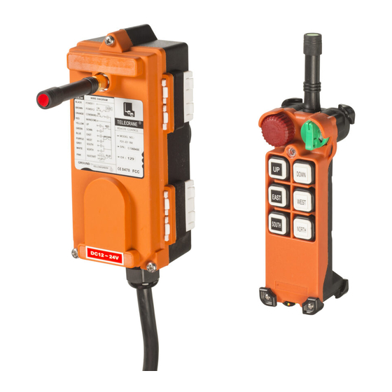
Summary of Contents for Telecrane F21-E1
- Page 1 Installation & Operation Manual FCC ID: LWNF21-E1 F21-E1 type Industrial Radio Remote Controller TELECRANE Lee’s Hi-tech Ent. Co., Ltd. 6/14/2002...
-
Page 2: Table Of Contents
Table Of Contents Part. 1 Operator’s Manual Chapter 1 Warranty Chapter 2 Precautions Of Operation Chapter 3 F21-E1 Standard Accessories Chapter 4 Operation Chapter 5 Troubleshooting and Software Installation... -
Page 3: Safety Considerations
Safety Considerations This product and related documentation must be reviewed for familiarization with safety markings and instructions before operation. Safety Symbols The following symbols may be found on the remote control or throughout the remote control’s documentation. Refer to Manual When product is marked with this symbol refer to instruction manual for additional information. -
Page 4: Part. 1 Operator's Manual
1-2 Warranty Period This equipment is warranted against defects in material and manufacturing for a period of one year from the date of shipment. During the warranty period, TELECRANE is responsible for necessary repairs as long as the product can be proved to be defective. -
Page 5: Chapter 2 Precautions Of Operation
However, this equipment must not be used in dangerous situations or where damage may result. ◎ After finishing operation of TELECRANE shut off main power to the crane, power to receiver, and remove transmitter key. If transmitter’s power is controlled by “rotary key switch”, then need turn the key to “OFF”... - Page 6 2-2 Precautions ☆ Operating in an industrial facility is highly dangerous, therefore, operator must have adequate training in using TELECRANE with this in mind. ☆ Those who operate the machine should be healthy and have good judgment in regards to safety.
- Page 7 2-3 Procedures of emergency The F21 system has various protections to guard against different emergencies including strict security code checking and automatic monitoring of parts failure. The F21 system has isolation circuitry to protect from outside voltage surges and interference. In the event of sensing an emergency situation the F21 will perform an emergency stop of the equipment.
-
Page 8: Chapter 3 F21-E1 Standard Accessories
Chapter 3 F21-E1 Standard Accessories When you get a standard and full set of F21-E1 system, it includes the following item.: (1)Transmitter, one unit. (2)Receiver, one unit. Remarks: (1). Hamming Distance-------------≧4 (2). I.D. Code--------------------------More than 42 billion ID Code(32bit) (3). Channel Spacing----------------267.5KHz... -
Page 9: Chapter 4 Operation
Chapter 4 Operation 4-1 F21-E1 Transmitter’s parts Rotary key Emergency stop Pushbuttons LED indicator Remarks: (1). Power----------------------Two 1.5Volt Alkaline Batteries(AA Size) (2). Dimensions----------------156×61×51mm (3). Weight---------------------about 320g(W/batteries)... - Page 10 4-2 F21-E1 Receiver’s parts Antenna Diagram of control contact with LED indicator Output cable Remarks: (1). Input Voltage------------------------------110VAC(50/60Hz)±10% (2). Output Relays-----------------------------10A/250VAC. (3). Dimensions---------------------------------185×85×85mm(L×W×H) (4). Weight--------------------------------------about 550g(W/O wire cable)...
- Page 11 (4). Insert the new crystal unit vertically into the PC board. (5). Press the new crystal down into the socket. 4-4-3 Independent COM Line: The new F21 crystal series provides the option of independent (separated) COM lines. F21-E1: 4 independent COM lines (Up/Down, East/West, South/North and R0)
- Page 12 If the independent COM Line is required, cut the wire labeled with a white “X.”. The longer part of the wire will become the new COM Line. Then you may connect this new COM wire with an output wire. 4-4-4 Replacing the Fuse Depress the fuse cover and turn counter-clockwise with flat screwdriver to open up the fuse cover.
- Page 13 4-4-7 Wire Diagram...
-
Page 14: Chapter 5 Troubleshooting And Software Installation
Chapter 5 Troubleshooting and Software Installation 5-1 LED Malfunction Alert (1) Red LED flashing quickly (every 0.2 sec) when any pushbutton is pressed. The problem could be: (a) One of the pushbuttons is jammed. (b) The EMS mushroom has not been released. (c) The system is not properly powered according to the instructions. - Page 15 FEDERAL COMMUNICATIONS COMMISSION This device complies with Part 15 of the FCC Rules. Operation is subject to the following two conditions:(1) this device may not cause harmful interference, and (2) this device must accept any interference received, including interference that may cause undesired operation.


Need help?
Do you have a question about the F21-E1 and is the answer not in the manual?
Questions and answers