Table of Contents
Advertisement
Advertisement
Table of Contents

Related Manuals for Telecrane F24+ Series


Summary of Contents for Telecrane F24+ Series
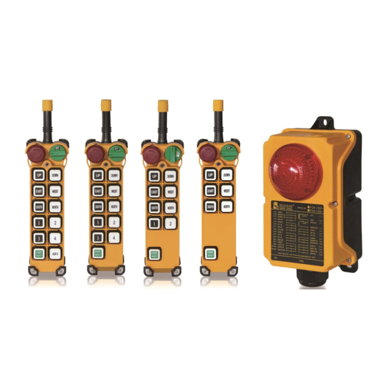
- Page 1 F24+ Series Radio Remote Control User Manual...
-
Page 2: Warranty Period
This equipment is warranted against defects in material and manufacturing for a period of one year from the date of shipment. During the warranty period, TELECRANE is responsible for necessary repairs as long as the product can be proven to be defective. - Page 3 Make sure that the batteries are in good condition and power for receiver is correctly supplied. The installation and maintenance service is allowed only when the receiver power is disconnected to avoid electrical shock. The contents of this manual may be amended by the manufacturer without notice. ...
-
Page 4: Chapter 1 F24+ Transmitter & Receiver Overview
Chapter 1 F24+ TRANSMITTER & RECEIVER OVERVIEW How to Start Pre-inspection 1. There is e-card on both transmitter and receiver. Make sure the e-card is correctly installed. 2. Place 4 AA batteries with correct direction. And lock the battery cover. : Before placing the batteries, make sure the Rotary KEY is on the OFF position Note 3. - Page 5 Transmitter LED indicator Three stages power indicator 1. Green color (Full power): Operate as usual. 2. Yellow color (Mid Power): Stop operation until new batteries are replaced. 3. Red (Low Power): A Stop signal will be sent to receiver automatically to turn off receiver. To avoid the interruption during operation, check battery power frequently.
-
Page 6: Specification
Specification General Specification Frequency: 430.00 ~ 438.00 MHz ID Code: 4.3 Billions sets Channel Space: 50KHz Hamming Distance :>20 Structure: Fiberglass reinforced plastic materials Operating Temp.: -30℃ ~ +85℃ Operating Distance: Up to 100 Meters Transmitter ... -
Page 7: Chapter 2 Installation & Setting
CHAPTER 2 INSTALLATION & SETTING Installation Precaution Switch off receiver and keep power disconnected during installation to avoid electrical shock. Keep away from spark (such as electrical motor, relay contactor, power line or any high voltage devices) during receiver installation. ... - Page 8 Receiver power voltage selection F24+ receiver provides transformer with 3 stages (i.e. 48VAC/220VAC/380VAC) that allows user to change input power on site. The designated voltage had been preset by the factory. Changing input power 1. Disconnect receiver power. 2. Unplug the connector (Fig. A) 3.
-
Page 9: Chapter 3 Software & Copy Funtions
Chapter 3 SOFTWARE & COPY FUNTIONS F24+ series PC Software Installation Insert F24+ CD into CD-ROM Drive, the “auto-run” program will be pop up automatically. Click “Next “for continue installation. Click “Install”... -
Page 10: Usb Driver Installation
Click "FINISH" for complete the installation. USB Driver Installation 1. Go back to the F24+ series PC program file, install “PL2303_Prolific_DriverInstaller_V.1.8.0”. 2. Double click PL2303 installer icon then the USB Driver program will be installed automatically. How to use F24+ series PC program ... - Page 11 Pick up the e-Card from transmitter or receiver, and insert into the slot at the side of USB cable. COM Port Selection: Select a COM port which USB cable is connected Read e-Card Setting: Writing to e-Card: Make sure the e-Card has been inserting into the slot of USB interface cable. ...
- Page 12 Changing pushbutton function Read data setting from e-Card. 1. From main (Function-Setting) page, click any function blocks you would like to program. The pushbutton function table will drop down immediately. 2. Select any function block from the list. 3. To change the other pushbutton function setting, please repeat steps 2 and 3. Note: For further information about the function definition, please refer to the ANNEX for more detail explanation.
- Page 13 Exit F24+ series PC Program: Click “EXIT” button to exit the program. e-Card Duplicate Procedure In addition to F24+ series PC Software procedure to copy the e-Card, the transmitter also provides easy, quick copying feature without using software. Check out the transmitter status Make sure the batteries are installed.
-
Page 14: Function Setting
ANNEX: DEFINITION OF FUNCTION SETTING TERMS Note:Make sure the e-Card setting matching the remote control hardware setting. i.e. Dual Motor only available to the remote control with double step button models. Function Setting Definition The relative relay is “ON” when the pushbutton is pressed and held; and relay is “off”... - Page 15 Function Setting Definition For 2 steps button model, only one relay active at a time i.e. press UP 1 step button, the UP1S relay turns on. And press to 2 step, the UP2S relay turns on while UP1S relay turns off. There are 2 modes for Dual Motor as below Dual Motors (1): The 1 step relay is not active (bypass) when pushbutton is Dual Motor...
-
Page 16: Power-On Mode
Function Setting Definition “Interlock Delay Time” is delay time between 2 opposite pushbuttons are being press one after another. i.e.: while crane is moving one direction (forward), moving opposite direction (backward) immediately would be dangerous specially when crane is hooking up the heavy object. The object may sway if crane does Interlock Delay Time not completely stop before moving into opposite direction. -
Page 17: Transmission Mode
Function Setting Definition The relative relay will be conducted within a certain time, in order to operate with short and precision movement. There are 2 ways to perform this function: Inching 1: Once “START” pushbutton is pressed, just presses the relative motion Inching 1 &2 pushbutton then can perform inching motion. - Page 18 Function Setting Definition If receiver doesn’t receive the correct signal over a particular time, then the receiver will go into “Relay-Off” or “Power-Off” mode. Relay-Off (Stop motion): Only the motion relays go to OFF status. The Main relay remains ON. As long as the correct signal received again, the remote Passive Act function can be operated without rebooting.
Need help?
Do you have a question about the F24+ Series and is the answer not in the manual?
Questions and answers