
Related Manuals for Telecrane F24-60N


Summary of Contents for Telecrane F24-60N
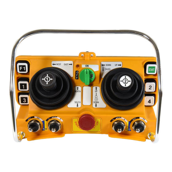
- Page 1 F24-60N Industrial Remote Controller Operating Manual ® TELECRANE Lee’s Hi-Tech Ent. Co., Ltd.
- Page 2 Table of Contents Warranty & Precautions of Operation..………….……...2 F24-60N Operation………………...…………….….…….4 F24-60N Software Quick Start ……………………..…….8 Definition of Function Terminology……………..……13 ...
- Page 3 ◎ Never dismantle the equipment by any unauthorized personnel, or equipment may be damaged. ◎ After finishing operation of TELECRANE radio controller shut off main power to the crane, power to receiver, and remove transmitter key. If transmitter’s power is controlled by “rotary key switch”, then need turn the key to “OFF”...
- Page 4 (4) 220/380 VAC Changing Frequency by Setting DIP Switch The dip switch of F24-60N allows users to set in 70 different frequency channels. And each channel is represented by a combination of 8 dip switch numbers. For example, CH #01 (Freq.
- Page 5 Dip Switch No. Freq. 433.0625 When the dip switch at position (1) is shifting to “ON” side (Shown as attached photo), that means the dip switch number becomes “1”. For another opposite side, it stands for dip switch number “0”. Note: Whenever changing the frequency, both the transmitter and receiver must be turned off the power and turned on again...
- Page 6 (Fig. A) (Fig. B) NC/NO output connection Relay module are designed for both type of relay such NO and NC/NO. Both outputs connection of NC/NO relay are available on the relay module. To replace NC/NO relay, remove existing NO relay and insert a new NC/NO relay. Follow the relay module indication for new output wire connections for NC/NO relay.
- Page 7 F24-60(N) Software Quick Start I. RELAY SELECTION Select quantity of relay to be used for each buttons, selector switch and joystick. (1) Choose COM PORT for your interface is assign (2) Press READ R/C (It may take a while to download the data from transmitter or receiver) (3) Pull down the menu and changing the number of relay to be used of each command.
- Page 8 II. FUNCTION SETTING Choose the function for selected buttons, selector switch, joystick and transmitter/receiver parameters. 1) Changing the setting as need and press NEXT when ready Note: You may return to previous step by press RETURN at any time. Refer to annex I for further explanation of all parameters.
- Page 9 III. JOYSTICK SETTING Joystick relay editing Joystick Setting is divided into 4 parts (1) Joystick No. 1 Y axis (2) Joystick No. 1 X axis (3) Joystick No. 2 Y axis (4) Joystick No. 2 X axis (1) Click relay table to edit relay output according to the command. Leave blank for disable.
- Page 10 IV. USER INFORMATION Save user information as record for future use. (1) Fill the necessary information as need. (2) Press WRITE R/C when ready to overwrite the existing data on transmitter or receiver. Note: You may return to previous step by press RETURN at any time. The user information is not saving in either transmitter or receiver memory, and it will be only saving into PC with D24 file format.
- Page 11 V. PRINT PREVIEW Print Preview allows you to have a print copy of receiver wire output which corresponding with all commands. (1) Press the printer icon to print the page. Note: Receiver output wire number is varied with command every time you change the settings.
- Page 12 (Annex I) Definition of Function Terminology The relative relay is “ON” when the pushbutton is pressed and held; and relay Normal is “off” when the pushbutton is released. Maintained function: the relay is operated by pressing and releasing; press Toggle and release again to turn off the relay.
- Page 13 *Only available under “continuous transmitting” mode. “LED-OFF”: LED indicator will remain OFF during normal operation to save battery LED ON/OFF power but it is still available for warning and fault indication. “LED-ON”: LED indicator will be lighten with green color when transmitting.
Need help?
Do you have a question about the F24-60N and is the answer not in the manual?
Questions and answers
Не понятно, есть в данной модели функция кратковременного срабатывания звукового сигнала при нажатии на пульте кнопки "пуск" для включения крана?