Advertisement
Table of Contents
- 1 Table of Contents
- 2 Safety Considerations
- 3 Part. 1 Operator's Manual
- 4 Chapter 1 Warranty
- 5 Chapter 2 Precautions of Operation
- 6 Chapter 3 Standard Accessories
- 7 Chapter 4 Operation
- 8 Chapter 5 Inspection and Fault Detection
- 9 Part. 2 Technician's Manual
- 10 Chapter 1 General Characteristics
- 11 Chapter 2 System Configuration
- 12 Chapter 3 Installation and Function Setting
- 13 Chapter 4 Software
- Download this manual
Advertisement
Table of Contents

Related Manuals for Telecrane F25


Summary of Contents for Telecrane F25
- Page 3 Installation & Operation Manual F25 Industrial Radio Remote Controlle Lee’s Hi-tech Enterprise. Co., Ltd.
-
Page 4: Table Of Contents
Table Of Contents Safety Considerations ------------------------------------------------------------2 Part. 1 Operator’s Manual Chapter 1 Warranty -----------------------------------------------------3 Chapter 2 Precautions Of Operation --------------------------------- 4 Chapter 3 Standard Accessories ---------------------------------------6 Chapter 4 Operation -----------------------------------------------------7 Chapter 5 Inspection and Fault Detection ---------------------------10 Part. 2 Technician’s Manual Chapter 1 General Characteristics -------------------------------------11 Chapter 2... -
Page 5: Safety Considerations
Safety Considerations This product and related documentation must be reviewed for familiarization with safety markings and instructions before operation. Safety Symbols The following symbols may be found on the remote control or throughout the remote control’s documentation. Refer to Manual When product is marked with this symbol refer to instruction manual for additional information. -
Page 6: Part. 1 Operator's Manual
This equipment is warranted against defects in material and manufacturing for a period of one year from the date of shipment. During the warranty period, TELECRANE is responsible for necessary repairs as long as the product can be proved to be defective. -
Page 7: Chapter 2 Precautions Of Operation
Chapter 2 Precautions of Operation 2-1 Attention ◎ Please carefully read the manual before installing and operating this device. ◎ Due to the complex nature of this equipment it is necessary to read the entire manual before installation. ◎ Never dismantle the equipment by any unauthorized personnel, or equipment may be damaged. - Page 8 ☆ Those who operate the machine should be healthy and have good judgment in regard to safety. ☆ Although the F25 transmitter is so durable and resistant for the fluctuating temperature, care still need be taken to prevent it from the severe impact or pressure.
-
Page 9: Chapter 3 Standard Accessories
Chapter 3 F25 Standard Accessories When you acquire a standard and full set of F25 system, it includes the following items. (1)Transmitter, one unit. (2)Receiver, one unit. -
Page 10: Chapter 4 Operation
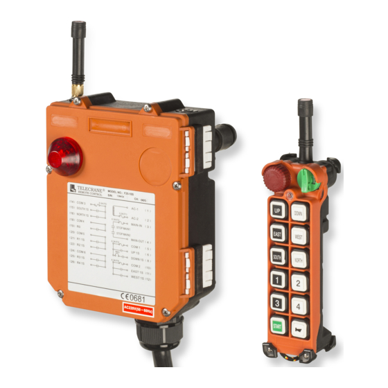
Chapter 4 Operation 4-1 F25 Transmitter’s parts EMS Button Antenna Rotary Key LED Indicator Motion Buttons Start Button Horn Button Battery Cover... - Page 11 4-2 F25 Receiver’s parts Antenna Power- On Indicator Wiring Diagram...
- Page 12 4–3 General Operation 1. Install four AA size batteries in the transmitter and make sure the "+" and "-" direction are correct. 2. Insert the rotary key into the keyhole at "OFF" position and then turn clockwise to "ON" position. 3.
-
Page 13: Chapter 5 Inspection And Fault Detection
5–2 Fault Detection F25 is equipped with simple fault detection mechanism. While start and during the operation, fault detection mechanism will indicate the faulty signals if any malfunction is detected. Operator must understand the faulty signals and notify the maintenance personnel. -
Page 14: Part. 2 Technician's Manual
Part 2. Technician’s Manual Chapter 1 General Characteristic 1–1 General Specifications - Operation Frequency--------------------- : 433.05~434.79MHz - Hamming Distance ----------------------- : ≧ 4 - I.D. Code----------------------------------- : 2 sets (set by factory, never repeated) - Temperature Range----------------------- : -40℃ ~ +85℃ - Channel Spacing-------------------------- : 25 KHz - Maximum Operation Range------------ : Up to 100 Meters - Structure----------------------------------- : Reinforced Plastic and Glass Fiber... -
Page 15: Chapter 2 System Configuration
Chapter 2. System Configuration 2–1 Transmitter Unit Control Data Antenna Data Encoder Transmitter Pushbuttons Circuit RF Circuit Figure A. Transmitter block diagram The transmitter unit consists of an Encoder Circuit and a Transmitter RF Circuit. When the user presses a pushbutton on the transmitter, the Encoder Circuit senses the pushbutton’s data immediately. - Page 16 Word" was so-called "Hamming Code" which may ensure the control data with accuracy in process of transmission, and also equip with function of automatic "Error detection/Error correction" to make sure the safety in operation of F25 system remote control. 2-3-1 Data Stream As shown as below, before the receiver’s relays output to control the equipment’s...
-
Page 17: Chapter 3 Installation And Function Setting
2-3-2 Hamming Code It is shown as below, the Code Word length is equal to 8, the Data Bit is equal to 4, the Hamming Distance is equal to 4, it means that HAMMING CODE (8,4,4) can correct single-bit errors and also detect double-bit errors. 1 0 1 0 1 0 0 0 BINARY... - Page 18 c. Select a place where there is no spark, e.g. keep away from motors, relays, magnetic switch and power cables. d. Keep away from high-voltage wiring and device. e. The Receiver’s box must be at least 3 cm away from the other obstacles. 3.
- Page 19 3-4 Power Supply and Change power supply voltage F25 receiver provides with 4 kinds of Transformer (24V/42V/230V 、 48V/110V/220V、110V/220V/380V、48V/220V/380V) that allows user to choose based on the power input on site and the designated voltage will be set when the receiver is made in factory.
- Page 20 1. Depress EMS mushroom pushbutton and turn the rotary key to “OFF” position. 2. Depress “START” pushbutton and hold it down, then turn the rotary key from “OFF” to “ON” position simultaneously. At this time, LED will fast flash in red, yellow, and green color alternately.
- Page 21 P.S. If the transmitter did not find any receiver, LED will flash in red 4 times and go off. It means that the Remote Pairing is failed and need to restart the procedures again. 3-6 Function Setting The radio data can be read and written by using Copier or F25 software through PC. Transmitter Receiver Copier *Please refer to the copier user manual for more detail.
-
Page 22: Chapter 4 Software
Chapter 4 Software 4-1 Software Installation F25 Software Installation 1. Insert F25 CD-ROM, the installation program will be executed automatically. 2. Press the “icon” and continue the installation 3. Press “Continue” button 4. Press “OK” button and installation of F25 software program is completed. - Page 23 How to start F25 Program 1. Press “Start” button 2. Select“Programs” 3. Select“F25 SETUP PROGRAM” 4. Then select“F25 SETUP PROGRAM” How to use F25 Program Note: Make sure both power of transmitter and receiver is remaining OFF when reading or writing the data.
- Page 24 Function Table) User-Information Customer data sheet: Allow you to store the customer information such as company name, purchasing date, address, and phone etc. 1. Click “User-Information” 2. Fill the information. Saving data To save radio function and customer data 1. Press Save button 2.
- Page 25 Press Printing button Note﹕ ﹕ ﹕ ﹕ Only in-use page will be printed when pressing printing button. In order to print other page, please switch to another page and press the print button again. Exit F25 Program Press exit button...
- Page 26 4-2 Definition of Function Setting Terms Normal The relative relay is “ON” when the pushbutton is pressed and held; and relay is “off” when the pushbutton is released. Toggle Maintained function: the relay is operated by pressing and releasing. Press the pushbutton and release once for “on”; press and release again to turn off the relay.
- Page 27 Dual Motor When 1 step pushbutton is pressed, the 1 step relay turns ON, if step is being pressed then 2 step relay turns ON and 1 step relay turns OFF. (For dual motor hoist) Relay Step Step Relay Relay Pushbutton Step Step...
- Page 28 R1,2,3 Toggle, R4 R1, R2, R3 pushbuttons are set as Toggle and R4 pushbutton no No Use use. This function is applied when the crane has 2 trolleys and need to control the trolleys separately or simultaneously. Press R1 pushbutton to control Trolley A, Press R2 pushbutton to control Trolley B, and Press R3 pushbutton to control both Trolley A &...
- Page 29 Transmit Mode “Non-continuous transmitting mode”: After “Power-On”, the transmitter will transmit the signal only when the pushbutton is pressed. This mode can save the power of transmitter. “Continuous transmitting mode”: Transmitter will continuously transmit signal once transmitter is being Power-On. Save Power This function is used to turn off the Transmitter after a given idle time.
- Page 30 Start-Alarm This function allows the user to activate the alarm of the receiver to work or not to work. If the “Enable (2 sec)” is chosen, then the alarm will make a 2-second sound when the receiver is powered on/off. TxPower(Range) The emission power of the transmitter is adjustable according to the user’s requirement.
- Page 32 Essential components of the technical construction file: Test report(s) Radio: W6M20708-8445-T-41 EMC: W6M20708-8445-E-11 Safety: W6M20708-8445-L User manual Technical Documentation F25-10D including: PCB Layout Circuit diagram Part list Declarations: Radio Acc. to article 3.2 : Acc. to article 3.1b : Safety...
Need help?
Do you have a question about the F25 and is the answer not in the manual?
Questions and answers