Table of Contents
Advertisement
Quick Links
Advertisement
Table of Contents

Related Manuals for Yaesu FT-818ND


Summary of Contents for Yaesu FT-818ND
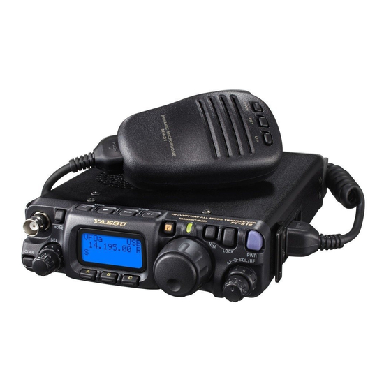
- Page 1 FT-818 Operating Manual HF/VHF/UHF SSB/CW/AM/FM ULTRA-COMPACT TRANSCEIVER...
-
Page 2: Table Of Contents
Contents Introduction ............1 ARTS (Auto Range Transpond System) Operation ............ 33 Safety Precautions .......... 2 CW Identifier Setup ........33 Accessories & Options ........4 Digital Mode Operation (SSB-Based AFSK) ..34 Supplied Accessories ........4 RTTY (Radio TeleType) Operation ..... 34 Available Options .......... -
Page 3: Introduction
Introduction The FT-818 is a compact, innovative multiband, multimode portable transceiver for the amateur radio MF/HF/VHF/UHF bands. Providing coverage of the 160-10 meter bands plus the 6 m, 2 m, and 70 cm bands, the FT-818 includes operation on the SSB, CW, AM, FM, and Digital modes, yielding the most comprehensive performance package available for portable operation. -
Page 4: Safety Precautions
Safety Precautions Note beforehand that the company shall not be liable for any damages suffered by the customer or third parties in using this product, or for any failures and faults that occur during the use or misuse of this product, unless otherwise provided for under the law. - Page 5 Safety Precautions Do not place the device in areas that may get Do not pull the cable when plugging and un- wet easily ( e.g. near a humidifier ) . plugging the power cord and connection ca- This may result in fire, electric shock and equip- bles.
-
Page 6: Accessories & Options
Accessories & Options Supplied Accessories MH-31 Hand Microphone SBR-32MH Ni-MH Battery Pack (9.6 V, 1900 mAh) PA-48B/C/U Battery Charger FBA-28 Battery Case (holds 8 “AA” size Alkaline cells [not supplied]) YHA-63 Whip Antenna for (50/144/430 MHz) E-DC-6 DC Cable Shoulder Strap Ferrite Core Rubber Foot... -
Page 7: Installation
Installation Connecting the Supplied YHA-63 Antenna Your FT-818 is supplied with a three-section antenna, model YHA-63 which is designed for optimum performance on the 50 MHz, 144 MHz, and 430 MHz. It also works well on the FM broadcast and other VHF bands. This antenna is intended for connection to the front panel’s BNC-type antenna connector. -
Page 8: Connecting The Microphone
Installation Connecting the Microphone To connect the microphone, plug its connector (latch side UP) into SP/PH SP PH the MIC jack on the right side of the transceiver. Press it gently inward until you hear the “click” of the latch. ... -
Page 9: Alkaline Battery Installation And Use
Installation Alkaline Battery Installation and Use The FT-818 is supplied with the FBA-28 holder for Alkaline “AA” cells. A fresh set of Alka- line cells should provide approximately 5.5 hours of reception under typical conditions. 1. To install or replace the AA cells, first remove the battery cover from the bottom side of the transceiver. -
Page 10: External Power Connections
Installation External Power Connections The FT-818 may be connected to an external 13.8 Volt DC power source providing at least 3 Amps of continuous-duty current.. The supplied E-DC-6 DC cable may be used for DC connections. While connected to an external DC source, if you have installed the supplied SBR-32MH Ni-MH Battery Pack, the E-DC-6 connection to the external DC power source will allow op- eration of the FT-818 while charging of the SBR-32MH is in progress. -
Page 11: Sbr-32Mh Ni-Mh Battery Pack Installation And Use
Installation SBR-32MH Ni-MH Battery Pack Installation and Use The supplied SBR-32MH Ni-MH Battery Pack provides 9.6 Volts of DC power for your FT- 818, with a maximum capacity of 1900 mAh. Installation 1. To install the SBR-32MH Ni-MH Battery Pack, first remove the battery compart- ment cover, as described previously. -
Page 12: Front Panel Control & Switches
Front Panel Control & Switches ⑮ ⑫ ⑪ ⑩ ⑧ ⑥ ⑤ ④ ① HOME LOCK SQL/RF CLAR ⑭ ⑬ ⑨ ⑦ ② ③ PWR Switch Press and hold in the switch for one second to turn to the transceiver on or off. AF Knob The (inner) knob adjusts the receiver audio volume level presented to the inter-... - Page 13 Front Panel Control & Switches FUNC Keys These three keys select many of the most important operating features of the trans- ceiver. When pressing the key, the current function of that key appears above each of the keys (along the bottom of the LCD); rotating the knob scrolls the display through eleven rows of functions available for use via the keys.
- Page 14 Front Panel Control & Switches Press the key to switch Press and hold in the Press the key to activate between VFO-A and VFO-B key for 1/2 second to copy the Split frequency operation be- on the display. contents of VFO-A into the tween VFO-A and VFO-B.
-
Page 15: Display Icons
Front Panel Control & Switches – Press the key to activate Press the key to select No function the receiver’s IF Noise Blank- t h e r e c o v e r y t i m e ( F a s t , Slow, Auto, or Off) for the receiver’s AGC system. -
Page 16: Side Panel Switch & Connectors
Side Panel Switch & Connectors SP/PH SP PH ① ② ③ MIC Jack Connect the supplied MH-31 Hand Microphone to this jack. MIC MIC GND +5 V FAST DOWN SP/PH Jack This 3.5-mm, 2-pin jack provides variable audio output for an external speaker (4 Ω - 16 Ω... -
Page 17: Rear Panel Connectors
Rear Panel Connectors ① ③ ④ ⑤ DATA INPUT DC13.8V ② ⑥ Jack ( INPUT:13.8V This is the DC power supply connection for the transceiver, used when operating the transceiver with an external power supply. Use the supplied DC cable to connect this jack to the car battery or base station DC power supply, which must be capable of supplying at least 3A @ 8 - 16 VDC. -
Page 18: Operation
Operation Turning the Transceiver On and Off 1. To turn the transceiver on, press and hold in the switch for one second. 2. To turn the transceiver off, again press and hold HOME LOCK SQL/RF in the switch for one second. CLAR The one-second delay helps you avoid acci- dental switching on (or off) of DC power. -
Page 19: Operating Band Selection
Operation Operating Band Selection This transceiver covers an incredibly wide fre- BAND DWN BAND UP quency range, over which a number of different operating modes are used. Therefore, this trans- HOME ceiver’s frequency coverage has been divided into LOCK SQL/RF different operating bands, each of with has its own CLAR preset channel steps and operating modes. -
Page 20: Menu Quick Start
Operation Menu Quick Start Many aspects of this transceiver’s configuration may be customized using the convenient “Menu” system, which allow you to configure many “set and forget” settings just the way you want to. A full discussion of the Menu system beings on page 52; for now, here is a brief discussion on how to change Menu settings: 1. -
Page 21: Setting The Operating Frequency
Operation Setting the Operating Frequency 1. In the “SSB/CW/DIG” modes, rotate the knob to set the frequency. Clockwise rotation HOME LOCK SQL/RF of the knob increases the operating fre- CLAR quency. 2. In the “AM/FM/PKT” modes, rotate the DIAL knob to set the frequency. Clockwise rotation of knob increases the operating frequency. -
Page 22: Operation On 5 Mhz Band (U.s. Version Only)
Operation Operation on 5 MHz Band ( U.S. Version Only ) The FT-818 includes the capability for transmission and reception on the five spot frequen- cies assigned to the Amateur Service in the United States. To operate on the 5 MHz band: 1. -
Page 23: Receiver Accessories
Receiver Accessories Clarifier ( Receiver Incremental Tuning ) The Clarifier allows you to set an offset of up to ±9.99 kHz of the receive frequency relative to your transmit frequency. To achieve a wider offset than this, you may use the “Split” op- erating mode, described later. -
Page 24: If Shift
Receiver Accessories IF SHIFT The receiver’s IF SHIFT feature is an effective interference-reduction tool, which allows you to shift the passband response higher or lower without changing the pitch of the in- coming signal. 1. Press the switch for one second to activate the IF SHIFT feature. -
Page 25: Noise Blanker
Receiver Accessories Noise Blanker The IF Noise Blanker may be useful in reducing or eliminating some types of impulse noise, especially noise generated by automotive ignition systems. 1. Press the key momentarily, then rotate the knob, as needed, until Operating Function Row 8 [ NB, AGC ] appears on the display. -
Page 26: Am/Fm Dial
Receiver Accessories AM/FM DIAL In the AM and FM modes, the knob is locked out (via the setting of Menu #04) so as to allow “channelized” tuning on these modes. To adjust the operating frequency, rotate knob. If you wish to enable the knob for tuning in the AM and FM modes, change the set- ting of Menu #04. -
Page 27: Transmitter Operation
Transmitter Operation SSB Transmission Basic Setup/Operation 1. Press the key so as to select either SSB (LSB/USB) mode. If you are operating on the 7 MHz or lower bands, select the LSB mode. If you are oper- ating on the 14 MHz or higher bands, select the USB mode. 2. -
Page 28: Vox Operation
Transmitter Operation VOX Operation The VOX system provides automatic transmit/receive switching based on voice input to the microphone. With the VOX system enabled, you do not need to press the PTT switch in order to transmit. 1. Press the key momentarily, then rotate the knob, as needed, until Operating Function Row 10 [ VOX, BK, KYR ] appears on the display. -
Page 29: Cw Transmission
Transmitter Operation CW Transmission Operation using Straight Key/External Keying Device When using a straight key, an external electronic keyer, or a computer-generated keying device, please follow the instructions in this section. 1. Insert your key’s (three-conductor) plug into the rear-panel KEY jack. 2. - Page 30 Transmitter Operation 8. You also can adjust the CW sidetone pitch using Menu #20 (CW PITCH). This adjust- ment also controls the BFO offset (actual pitch of your transmitted signal relative to your current receive frequency). To adjust the CW sidetone pitch: ...
-
Page 31: Operation Using Built-In Electronic Keyer
Transmitter Operation Operation using Built-in Electronic Keyer The built-in Electronic Keyer provides a convenient method of generating CW. The Elec- tronic Keyer includes weight and speed adjustments. 1. Connect your keyer paddle’s cable to the KEY jack on the rear panel of the transceiver. 2. -
Page 32: Fm Transmission
Transmitter Operation FM Transmission Basic Setup/Operation 1. Press the key so as to select the FM mode. 2. Press the microphone’s PTT switch, and speak into the microphone in a normal voice. 3. Release the PTT switch to return to the receive mode. 4. - Page 33 Transmitter Operation code), followed by “ ” (Digital Coded Squelch, Encode/Decode). One additional press will disable all repeater-access tone systems. See the next section for a discus- sion of DCS operation. 5. If the default repeater access tone are not appropriate for your area, it also may be set independently for each band.
-
Page 34: Dcs Operation
Transmitter Operation DCS Operation Another form of tone access control is Digital Code Squelch, or DCS. It is a newer, more advanced tone system that is less susceptible to false triggering than CTCSS. A DCS En- coder/Decoder is built into your transceiver, and operation is very similar to that described above for CTCSS. -
Page 35: Arts Tm (Auto Range Transpond System) Operation
Transmitter Operation ( Auto Range Transpond System ) Operation ARTS The ARTS system uses DCS signaling to inform you when you and another ARTS™- equipped station are within communications range. This can be especially valuable during search-and-rescue operations, as a base station can quickly use ARTS™ to alert a field unit that it is out of range;... -
Page 36: Digital Mode Operation (Ssb-Based Afsk)
Transmitter Operation Digital Mode Operation ( SSB-Based AFSK ) The FT-818 provides extensive capability for digital mode operation on the HF, VHF, and UHF bands. The use of AFSK (Audio Frequency-Shifted Keying) configurations allows a wide variety of different communication modes to be utilized. The Menu provides for spe- cific digital mode selections, which include custom BFO offsets to optimize the receive and transmit passbands for the mode selected. -
Page 37: Psk31 Operation
Transmitter Operation 4. If the optional YF-122C 500 Hz filter has been installed, it may be used for RTTY work. Recall Operating Function Row 7 [ IPO, ATT, NAR ] then press the ( NAR ) key to en- gage the narrow filter. 5. -
Page 38: User" Defined Digital Modes
Transmitter Operation “USER” Defined Digital Modes Also provided in the FT-818 are two convenient “USER” Digital modes, one each providing USB- and LSB-side injection, which may be used for SSTV, Fax, Pactor, and other digital operating modes. Here is an example involving the configuration of the USER mode for RTTY with USB-side injection (as opposed to LSB injection, used in the default “RTTY”... -
Page 39: Packet (1200/9600 Bps Fm) Operation
Transmitter Operation Packet ( 1200/9600 bps FM ) Operation The FT-818 is designed for operation on either 1200 bps or 9600 bps packet, and set- up is similar to that described previously for SSB-based modes. A separate Data input adjustment is provided, allowing you to optimize the deviation on the FM Packet modes separately from the SSB-based Digital modes. -
Page 40: Am Transmission
Transmitter Operation AM Transmission The FT-818 utilizes low-level amplitude modulation of an early stage for transmission pur- poses. This capability is primarily provided for emergency use only, as low-power opera- tion typically utilizes more efficient transmission/reception modes. The AM carrier level is preset to 2 Watts during alignment at the factory, and should not require further adjustment. -
Page 41: Time-Out Timer
Transmitter Operation Time-Out Timer Most often used on FM, the transmitter’s Time-Out Timer (TOT) feature disables the trans- mitter after a user-defined period of transmission. This feature may be useful in preventing a “stuck microphone” (accidental closure of the PTT switch) from causing interference to other users, and it will also force you to keep your transmission short, thereby conserving battery power. -
Page 42: Memory Operation
Memory Operation QMB Channel QMB Channel Storage 1. Tune in the desired frequency and set the operating mode and bandwidth. If this is an FM channel, set up any required CTCSS/DCS and repeater shift configurations. 2. Press and hold in the key until a double “beep”... -
Page 43: Memory Operation On "Regular" Memory Channels
Memory Operation Memory Operation on “Regular” Memory Channels Normal Memory Storage 1. Tune in the desired frequency, and set the operating mode and bandwidth. If this is an FM channel, set up any required CTCSS/DCS and repeater shift configurations. Stan- dard (default) repeater shifts do not require you to utilize the “split”... -
Page 44: Memory Channel Recall
Memory Operation Memory Channel Recall 1. If you currently are in the VFO tuning mode, press the key once to enter the “Mem- ory” mode (a memory channel number “M-nnn” will appear on the display in she space previously occupied by “VFOa” or “VFOb”). 2. -
Page 45: Memory Operation On "Home" Channel Memories
Memory Operation Memory Operation on “HOME” Channel Memories Four Special one-touch “Home” channels are available, for special frequencies you use often. Either “simplex” or “split” frequency/mode data may be stored in the “Home” channel locations. Special “Home” channels are available for HF (any frequency between 1.8 and 29.7 MHz), 50 MHz, 144 MHz, and 430 MHz. -
Page 46: Labeling Memories
Memory Operation Labeling Memories You may wish to append an alpha-numeric “Tag” (label) to a memory or memories, to aid in recollection of the channel’s intended use (such as a club name, etc.). This is easily ac- complished using the Menu mode. 1. -
Page 47: Setting The Spectrum Scope Mode
Spectrum Scope Monitor Operation Note: This operation does not function in the FM Broadcast frequencies. The Spectrum Scope Monitor allows viewing of operating activity on 5 channels above and 5 channels below the current operating channel in the VFO mode. When the Spectrum Scope Monitor is activated, the display indicates the relative signal strength on channels immediately adjacent to the current operating frequency. -
Page 48: Smart Search™ Operation
Smart Search™ Operation Note: This operation does not function in the FM Broadcast frequencies. The Smart Search feature automatically stores frequencies where activity is encountered on the current band. When Smart Search is engaged, the transceiver quickly searches above your current frequency, storing active frequencies as it goes (without stopping on them even momentarily). -
Page 49: Scanning Operation
Scanning Operation Note: This operation does not function in the FM Broadcast frequencies. This transceiver contains a wide variety of scanning capabilities. Whether you are in the VFO mode or one of the memory modes, scanning operation is fundamentally identical in all configurations, but with the following differences: ... -
Page 50: Scan Skip Programming (Memory Mode Only)
Scanning Operation Scan Skip Programming (Memory Mode Only) Among the memories you have programmed, there may be some stations which you do not wish to scan. For example, broadcast signals (which are transmitted continuously) will cause the scanner to stop, and such channels may be skipped so as to avoid this inconve- nience. -
Page 51: Programmable Memory Scan (Pms) Operation
Scanning Operation Programmable Memory Scan (PMS) Operation To limit scanning (or tuning) within a particular frequency range, you can use the Program- mable Memory Scanning (PMS) feature, which utilizes special-purpose memory pair (“M- PL” and “M-PU”). The PMS feature is especially useful in helping you to observe any oper- ating sub-band limits which apply to your Amateur license class. -
Page 52: Dual Watch Operation
Dual Watch Operation Note: This operation does not function in the FM Broadcast frequencies. Dual Watch is similar, in some respects, to scanning. In Dual Watch, however, the trans- ceiver monitors (squelched) on the VFO-A frequency while periodically checking VFO-B for activity (or vice-versa). -
Page 53: Operation On Alaska Emergency Frequency: 5167.5 Khz (U.s. Version Only)
Operation on Alaska Emergency Frequency: 5167.5 khz ( U.S. Version Only ) Section 97.401(d) of the regulations governing amateur radio in the United States permit emergency amateur communications on the spot frequency of 5167.5 kHz by stations in (or within 92.6 km of) the state of Alaska. This frequency is only to be used when the immedi- ate safety of human life and/or property are threatened, and is never to be used for routine communications. -
Page 54: Menu Operation
Menu Operation The Menu System allows you to customize a wide variety of transceiver performance aspects and operating characteristics. Once you have gone through the various Menu customization procedures initially, you will find that you will not have to resort to them fre- quently during everyday operation. - Page 55 30 FM STEP 2 mode 20/25/50 kHz 31 ID Store your callsign into the CW identifier – YAESU 32 LOCK MODE Select the operation of the front panel’s DIAL/FREQ/PANEL DIAL 33 MAIN STEP Setting of the ’s tuning speed...
- Page 56 Menu Operation Menu Item 01 [144 ARS] Function: Activate/deactivate the Automatic Repeater Shift when operating on the 144 MHz band. Available Values: OFF/ON Default: ON (depending on transceiver version) Menu Item 02 [430 ARS] Function: Activate/deactivate the Automatic Repeater Shift when operating on the 430 MHz band.
- Page 57 Menu Operation Menu Item 09 [ARTS BEEP] Function: Select the ARTS beep mode. Available Values: OFF/RANGE/ALL Default: RANGE OFF: No alert beeps sound; you must look at the display to determine current ARTS status. RANGE: A high tone beep will sound when the transceiver first detects that you are within range, and a low beep will sound when the other station goes out of range.
- Page 58 Menu Operation Menu Item 16 [CONTRAST] Function: Setting of the display contrast level. Available Values: 1 ~ 12 Default: 5 Menu Item 17 [CW DELAY] Function: Set the receiver recovery time during pseudo-VOX CW semi-break-in opera- tion. Available Values: 10 ~ 500 msec Default: 250 msec The recovery time may be adjusted in steps of 10 msec.
- Page 59 Menu Operation Menu Item 22 [CW WEIGHT] Function: Set the Dot:Dash ratio for the built-in electronic keyer. Available Values: 1:2.5 ~ 1:4.5 Default: 1:3.0 Menu Item 23 [DCS CODE] Function: Setting the DCS code. Available Values: 104 Standard DCS codes Default: 023 DCS Code Menu Item 24 [DIG DISP]...
- Page 60 3. Repeat the previous step as many times as necessary to complete your callsign. 4. Press the knob to save your completed callsign and exit. Default: YAESU...
- Page 61 Menu Operation Menu Item 32 [LOCK MODE] Function: Select the operation of the front panel’s key. Available Values: DIAL/FREQ/PANEL Default: DIAL DIAL: Locks knob only FREQ: Locks front panel keys and knobs related to frequency control (such as ( A/B ) key., etc.) key, PANEL: Locks all front keys and knobs (except key and...
- Page 62 Menu Operation Menu Item 37 [MIC SCAN] Function: Enable/disable scanning access via the microphone’s [ UP ] / [ DWN ] keys. Available Values: OFF/ON Default: ON Menu Item 38 [OP FILTER] Function: Enable the optional filter (CW or SSB) path. Available Values: OFF/SSB/CW Default: OFF After installing the optional filter, set this Menu Item to define the signal path corresponding...
- Page 63 Menu Operation Menu Item 45 [SQL/RF-G] Function: Select the configuration of the front panel’s knob. Available Values: RF-GAIN/SQL Default: Depends on transceiver version Menu Item 46 [SSB MIC] Function: Adjust the microphone gain level for the SSB mode. Available Values: 0 ~ 100 Default: 50 Menu Item 47 [SSB STEP] Function: Select the tuning steps for the...
- Page 64 Menu Operation Menu Item 53 [DCS INV] Function: Select “Normal” or “Inverted” DCS coding. Available Values: Tn-Rn/Tn-Riv/Tiv-Rn/Tiv-Riv Default: Tn-Rn “n” = “normal “iv” = “inverted” Menu Item 54 [R LSB CAR] Function: Set the Rx Carrier Point for LSB Available Values: –300 ~ +300 Hz Default: 0 Hz Menu Item 55 [R USB CAR] Function: Set the Rx Carrier Point for USB...
-
Page 65: Cloning
Cloning You can transfer all data stored in one transceiver to another set by utilizing the handy “Cloning” feature. This requires a user-constructed cloning cable which connects the ACC jacks on the two transceivers as shown below. To clone from one transceiver to another, use the following procedure: 1. -
Page 66: Cat System Programming
ACC jack to the serial port of your computer, without the need for an external RS- 232C level converter box. Yaesu Musen does not produce CAT System operating software, due to the wide variety of personal computers, operating systems, and applications in use today. However, the FT-... -
Page 67: Cat Data Protocol
CAT System Programming CAT Data Protocol All commands sent from the computer to the transceiver consist of five-byte blocks, with up to 200 ms between each byte. The last byte in each block is the instruction opcode, while the first four bytes of each block are arguments (either parameters for that instruc- tion, or dummy values required to pad the block out to five bytes). -
Page 68: Opcode Command Chart
CAT System Programming Opcode Command Chart Command Title Parameter Opcode Notes CMD = 00: LOCK ON LOCK ON/OFF CMD = 80: LOCK OFF CMD = 08: PTT ON PTT ON/OFF CMD = 88: PTT OFF P1 ~ P4: Frequency Digits P1 P2 P3 P4 Set Frequency... - Page 69 CAT System Programming Note 1: CTCSS Tone Note 4: Read TX Status 7 6 5 4 3 2 1 0 CTCSS Tone Frequency (Hz) 67.0 69.3 71.9 74.4 77.0 79.7 PO Meter Data Dummy Data 82.5 85.4 88.5 91.5 94.8 97.4 SPLIT Status 100.0 103.5 107.2 110.9 114.8 118.8...
-
Page 70: Installation Of Optional Accessories
Installation of Optional Accessories Optional Filters YF-122S/YF-122C/YF-122CN 1. Turn the transceiver’s power off by pressing and holding in the switch for 1/2 sec- ond, then remove the FBA-28 Battery Case or SBR-32MH Ni-MH Battery Pack from the transceiver. Additionally, disconnect the DC cable from the INPUT: 13.8V jack on the rear panel of the transceiver, when operating the FT-818 with a DC power supply. -
Page 71: Power-On Microprocessor Reset Procedure
Power-on Microprocessor Reset Procedure Some or all transceiver settings can be reset to their factory-default states using one of the following power-on routines: + POWER on: Reset all memories and following menu setting to factory-default. Menu #06 (AM STEP), 23 (DCS CODE), 30 (FM STEP), 35 (MEM TAG), 42 (RPT SHIFT), 47 (SSB STEP), and 48 (TONE FREQ). -
Page 72: Specifications
Specifications General Frequency Range: Receive: 100 kHz-30 MHz 50 MHz-54 MHz 76 MHz-154 MHz 420 MHz-470 MHz Transmit: 160-6 Meters 2 Meters 70 Centimeters (Amateur bands only) 5.1675 MHz Alaska Emergency Frequency (USA only) Emission Modes: A1A (CW), A3E (AM), J3E (LSB/USB), F3E (FM), F1D (9600 bps packet), F2D (1200 bps packet) Synthesizer Steps (Min.): 10 Hz (CW/SSB), 100 Hz (AM/FM) - Page 73 Specifications Receiver Circuit Type: Double-Conversion Superheterodyne (SSB/CW/AM/FM) Single-Conversion Superheterodyne (WFM) Intermediate Frequencies: 1st: 68.33 MHz (SSB/CW/AM/FM); 10.7 MHz (WFM) 2nd: 455 kHz Sensitivity: SSB/CW 100 kHz - 500 kHz – – – 500 kHz - 1.8 MHz – 32 µV –...
- Page 74 Limited Warranty is valid only in the country/region where this product was originally purchased. On-line Warranty Registration: Thank you for buying YAESU products! We are confident your new radio will serve your needs for many years! Please register your product at www.yaesu.com - Owner’s Corner...
-
Page 75: Eu Declaration Of Conformity
SERVICE SIGNALS IS PROHIBITED UNDER FCC RULES AND FEDERAL LAW. EU Declaration of Conformity We, Yaesu Musen Co. Ltd of Tokyo, Japan, hereby declare that this radio equipment FT-818 is in full compliance with EU Radio Equipment Directive 2014/53/EU. The full text of the Declaration of Conformity for this product is available to view at http://www.yaesu.com/jp/red... - Page 76 Copyright 2018 YAESU MUSEN CO., LTD. All rights reserved. No portion of this manual may be reproduced without the permission of YAESU MUSEN CO., LTD. YAESU MUSEN CO., LTD. Tennozu Parkside Building 2-5-8 Higashi-Shinagawa, Shinagawa-ku, Tokyo 140-0002 Japan YAESU USA 1802S-CM 6125 Phyllis Drive, Cypress, CA 90630, U.S.A.
Need help?
Do you have a question about the FT-818ND and is the answer not in the manual?
Questions and answers