Yaesu FT-817 Operating Manual
Hf/vhf/uhf all mode
Hide thumbs
Also See for FT-817:
- Technical supplement (111 pages) ,
- Manual (43 pages) ,
- Operating manual (23 pages)
Table of Contents
Advertisement
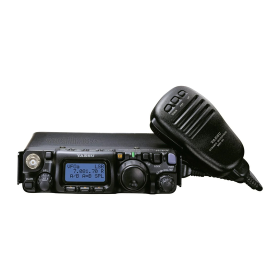
HF/VHF/UHF
ALL MODE TRANSCEIVER
FT-817
O
PERATING
VERTEX STANDARD CO., LTD.
4-8-8 Nakameguro, Meguro-Ku, Tokyo 153-8644, Japan
VERTEX STANDARD
US Headquarters
10900 Walker Street, Cypress, CA 90630, U.S.A.
YAESU EUROPE B.V.
P.O. Box 75525, 1118 ZN Schiphol, The Netherlands
YAESU UK LTD.
Unit 12, Sun Valley Business Park, Winnall Close
Winchester, Hampshire, SO23 0LB, U.K.
VERTEX STANDARD HK LTD.
Unit 5, 20/F., Seaview Centre, 139-141 Hoi Bun Road,
Kwun Tong, Kowloon, Hong Kong
M
ANUAL
Advertisement
Table of Contents

Related Manuals for Yaesu FT-817


Summary of Contents for Yaesu FT-817
- Page 1 4-8-8 Nakameguro, Meguro-Ku, Tokyo 153-8644, Japan VERTEX STANDARD US Headquarters 10900 Walker Street, Cypress, CA 90630, U.S.A. YAESU EUROPE B.V. P.O. Box 75525, 1118 ZN Schiphol, The Netherlands YAESU UK LTD. Unit 12, Sun Valley Business Park, Winnall Close Winchester, Hampshire, SO23 0LB, U.K.
-
Page 2: Table Of Contents
FM Transmission ..........33 Introduction ............ 1 Basic Setup/Operation ........33 Specifications ..........2 Accessories & Options ........4 Repeater Operation ........33 Plug Pinout ............5 Tone Search Scanning ....... 35 Installation ............6 DCS Operation ..........36 Connecting the Supplied YHA-63 Antenna ..6 DCS Search Scanning ....... -
Page 3: Introduction
MF/HF/VHF/UHF bands. Providing coverage of the 160-10 meter bands plus the 6 m, 2 m, and 70 cm bands, the FT-817 includes operation on the SSB, CW, AM, FM, and Digital modes, yielding the most comprehensive performance package available for portable operation. -
Page 4: Specifications
FM Maximum Deviation: ±5 kHz (FM-N: ±2.5 kHz) –50 dB (1.8-29.7 MHz) Spurious Radiation: –60 dB (50/144/430 MHz) >40 dB Carrier Suppression: Opp. Sideband Supp.: >50 dB SSB Frequency Response: 400 Hz-2600 Hz (–6 dB) Microphone Impedance: 200-10k Ohms (Nominal: 600 Ohms) FT-817 Operating Manual... - Page 5 1.0 W (8 Ohms, 10% THD or less) AF Output: 4-16 Ohms AF Output Impedance: Specifications are subject to change without notice, and are guaranteed within amateur bands only. Frequency ranges vary according to transceiver version; check with your dealer. FT-817 Operating Manual...
-
Page 6: Accessories & Options
Ni-Cd Battery Charger YF-122S Collins SSB Filter (2.3 kHz/4.7 kHz: –6 dB/–66 dB) YF-122C Collins CW Filter (500 Hz/2 kHz: –6 dB/–60 dB) TCXO-9 TCXO Unit (±0.5 ppm) MH-36E8J DTMF Microphone CT-62 Interface Cable CT-39A Packet Cable FT-817 Operating Manual... -
Page 7: Plug Pinout
INOUT FT-817 Operating Manual... -
Page 8: Installation
UPPLIED NTENNA Your FT-817 is supplied with a three-section antenna, model YHA-63 which is designed for optimum performance on the 50 MHz, 144 MHz, and 430 MHz. It also works well on the FM broadcast and other VHF bands. This antenna is intended for connection to the front panel’s BNC-type antenna connector. -
Page 9: Connecting The Microphone
817 transceiver. Refer to the illustration, and connect the shoulder strap to the attachment tabs just behind the front panel of the FT-817. Be sure to have the shoulder strap aligned correctly, without twists in the straps. A convenient microphone hanger is located on one end of the padded top section of the Shoulder Strap. -
Page 10: Alkaline Battery Installation And Use
ATTERY NSTALLATION AND The FT-817 is supplied with the FBA-28 holder for Alkaline “AA” cells. A fresh set of Alka- line cells should provide approximately 5.5 hours of reception under typical conditions. 1. To install or replace the AA cells, first remove the battery cover from the bottom side of the transceiver. -
Page 11: External Power Connections
XTERNAL OWER ONNECTIONS The FT-817 may be connected to an external 13.8 Volt DC power source providing at least 3 Amps of continuous-duty current.. The supplied E-DC-6 DC cable may be used for DC connections. While connected to an external DC source, if you have installed the optional FNB-72 Ni-Cd Battery Pack, the E-DC-6 connection to the external DC power source will allow operation of the FT-817 while charging of the FNB-72 is in progress. -
Page 12: Ni-Cd Battery Pack Installation And Use
2. Lift out the FBA-28 battery holder, and disconnect the short cable connected to the FBA-28, as shown in the illustration. 3. Connect the short cable to the mating connector on the FNB-72, and install the FNB-72 in the battery compartment. 4. Replace the battery compartment cover. FNB-72 FBA-28 FT-817 Operating Manual... - Page 13 Charging of the FNB-72 requires the use of either the optional NC-72B/C* charger, or an external 13.8 Volt (±15%) DC source. If the NC-72B/C is used, the FT-817 must be turned off during charging; if an external 13.8 Volt DC source is used (connected via the supplied E-DC-6 cable), then you may operate the FT-817 while charging is in progress.
-
Page 14: Front Panel Control & Switches
“Menu” setting in the transceiver. F Key Pressing this key momentarily changes the display to show the operating functions avail- able via the keys. Press and hold this key for one second to activate the “Menu” mode. FT-817 Operating Manual... - Page 15 50Ω impedance) to this BNC connector. In its default setting, this jack does not function on the HF bands. If you want to enable this jack on the HF bands, recall and change the setting of Menu #07. FT-817 Operating Manual...
- Page 16 144/430 MHz. lects the low-deviation mode function on 144/430 MHz. required for HF FM operation on 29 MHz. Press and hold in the for 1/2 second to recall Menu #38 (to Enable/Disable the optional filter during installa- tion). FT-817 Operating Manual...
- Page 17 #11 (for selecting the Charg- ing period). – Press the key to initiate Press the key to initiate No function Tone Search. DCS Search. *The Operating Function number in this column does not appear on the LCD. Display Icons FT-817 Operating Manual...
-
Page 18: Side Panel Switch & Connectors
SP-PH Switch If you use earphones with this transceiver, move this switch to the “PH” position before inserting the earphone plug into the SP/PH Jack, to prevent injury your ears. FT-817 Operating Manual... -
Page 19: Rear Panel Connectors
Connect your HF and/or 50 MHz antenna’s 50 Ω coaxial cable to this M-type (“SO- 239”) connector. In its default setting, this jack does not function on 50/144/430 MHz bands. If you want to enable this jack on 50/144/430 MHz bands, recall and change the settings of Menu #07. FT-817 Operating Manual... -
Page 20: Operation
Hi! I’m R.F. Radio, and I’m here to guide you through the fine points of the setup and use of your new FT-817. I know your anxious to get on the air, but I encour- age you to read the “Operation” section of this manual as thoroughly as possible, so you’ll get the most out of this fantastic new rig. -
Page 21: Operating Band Selection
DATA jack is a fixed-level audio signal. Start with the knob set fully counter-clockwise, especially when using FM (the background noise on FM can be surprisingly loud)! FT-817 Operating Manual... -
Page 22: Menu Quick Start
“RF Gain” control, however, and it normally should be set fully clockwise. If this control is configured for “SQL” operation, the FT-817’s RF Gain will be set for maximum sensitivity in all modes, and the control will function solely as a Squelch control. -
Page 23: Setting The Operating Frequency
VFOs provided on each Amateur band, so you may set VFO-A to the CW sub-band, and VFO-B to the SSB sub-band, if you like. The operating mode will be preserved, along with the frequency information, on each VFO. FT-817 Operating Manual... -
Page 24: Clarifier (Receiver Incremental Tuning)
The Clarifier will reset to zero after the first “step” of the knob. [ TX=RX ] If you leave the Clarifier on, moving the knob will not cause the offset to be cancelled. FT-817 Operating Manual... -
Page 25: Receiver Accessories
See page 68. Engaging of the IF Shift feature does not disable the set- ting of the Clarifier control. With the IF Shift activated, press the switch momentarily to switch to Clarifier operation. FT-817 Operating Manual... -
Page 26: Agc (Automatic Gain Control)
IPO feature will provide substantial protection against intermodulation and other problems associated with strong signal input to the receiver. Rule of thumb: so long as the S-meter is moving on background noise, additional front-end gain is not necessary. FT-817 Operating Manual... -
Page 27: Att (Front End Attenuator)
The “channelized” mode of tuning on AM and FM automatically rounds off the frequency to the next “logical” step when you rotate the knob one “click” in either direction. This eliminates the inconvenience of having to preset the frequency to an “even” channel. FT-817 Operating Manual... -
Page 28: Automatic Power-Off Feature
Just press and hold in the switch for one second to turn the transceiver back on after an APO shutdown, as usual. FT-817 Operating Manual... - Page 29 ECEIVER CCESSORIES FT-817 Operating Manual...
-
Page 30: Transmitter Operation
(which are rich in high-frequency components) are frequently more important. Adjusting the Transmitter Power Output Four power levels are available on the FT-817: 5 Watts, 2.5 Watts, 1 Watt, and 0.5 Watt. When using Alkaline batteries or the optional FNB-72 Ni-Cd Battery Pack, the microprocessor, detecting internal battery use, automatically sets the power level to 2.5 Watts, which appears on the display as “... -
Page 31: Vox Operation
The delay time for return to the receive mode is set independently on CW and voice modes; for CW, use Menu #17 (see next section). FT-817 Operating Manual... -
Page 32: Cw Transmission
“0” ~ “100,” the default value is “50.” When done, press and hold in the key for one second to save the new setting and exit to normal operation. FT-817 Operating Manual... - Page 33 “zero beat” with the other station. The FT-817 can generate a “CW Spot” tone; just press and hold in the key while in the CW mode.
-
Page 34: Operation Using The Built-In Electronic Keyer
Rotate the knob to select Menu #19 (CW PADDLE). Rotate the knob to select the new setting. When done, press and hold in the key for one second to save the new setting and exit to normal operation. FT-817 Operating Manual... -
Page 35: Fm Transmission
( RPT ) key for one second. This instantly recalls Menu #42 Press and hold the (RPT SHFT). Rotate the knob to select the desired shift frequency. When done, press and hold in the key for one second to save the new setting and exit to normal operation. FT-817 Operating Manual... - Page 36 If you wish to change the settings for the ARS, use Menu #01 (144 ARS) or Menu #02 (430 ARS) (see page 60). If your local repeaters need a 1750-Hz burst tone for access (typically in Europe), press and hold in the front panel’s key to transmit the burst tone. FT-817 Operating Manual...
-
Page 37: Tone Search Scanning
( TCH ) key for one second; the CTCSS tone detected 4. Press and hold in the will be stored as the “current” tone, so it may be used for memory storage pur- poses, and you may now exit to normal operation. FT-817 Operating Manual... -
Page 38: Dcs Operation
4. Press and hold in the (DCH) key for one second; the DCS code detected will be stored as the “current” code, so it may be used for memory storage purposes, and you may now exit to normal operation. FT-817 Operating Manual... -
Page 39: Operation
(your callsign) K” in Morse code every ten minutes during ARTS™ operation. To program the CW IDer, use Menu #31 (ID), as described on page 64. And to activate the CW IDer, use Menu #18 (CW ID). FT-817 Operating Manual... -
Page 40: Digital Mode Operation (Ssb-Based Afsk)
PERATION ASED The FT-817 provides extensive capability for digital mode operation on the HF, VHF, and UHF bands. The use of AFSK (Audio Frequency-Shifted Keying) configurations allows a wide variety of different communication modes to be utilized. The Menu provides for spe- cific digital mode selections, which include custom BFO offsets to optimize the receive and transmit passbands for the mode selected. -
Page 41: Psk31 Operation
For BPSK work, the injection does not matter, but for QPSK the two working stations must use the same sideband. Connect the FT-817 to your computer’s sound card or interface. Setup for PSK31 operation is basically identical to that previously described for RTTY operation. -
Page 42: User" Defined Digital Modes
PERATION ASED “USER” Defined Digital Modes Also provided in the FT-817 are two convenient “USER” Digital modes, one each provid- ing USB- and LSB-side injection, which may be used for SSTV, Fax, Pactor, and other digital operating modes. Here is an example involving the configuration of the USER mode for RTTY with USB-side injection (as opposed to LSB injection, used in the default “RTTY”... -
Page 43: Packet 1200/9600 Bps Fm Operation
ACKET PERATION The FT-817 is designed for operation on either 1200 bps or 9600 bps packet, and setup is similar to that described previously for SSB-based modes. A separate Data input adjustment is provided, allowing you to optimize the deviation on the FM Packet modes separately from the SSB-based Digital modes. -
Page 44: Am Transmission
PERATION AM T RANSMISSION The FT-817 utilizes low-level amplitude modulation of an early stage for transmission pur- poses. This capability is primarily provided for emergency use only, as low-power operation typically utilizes more efficient transmission/reception modes. The AM carrier level is preset to 1.5 Watts during alignment at the factory, and should not require further adjustment. -
Page 45: Time-Out Timer
EATHER ONITORING Monitoring of HF WeatherFax broadcasts is easily accomplished using the FT-817. 1. Before proceeding, be certain that the WeatherFax demodulator is properly connected to Pins 5 (DATA OUT 1200bps) and 2 (GND) of the rear panel DATA jack. -
Page 46: Memory Operation
When this is done, the “MTQMB” ( RCL ) will appear in the display, where “MT” represents “Memory Tuning.” Press the key once more to return to the originally-stored QMB frequency. FT-817 Operating Manual... -
Page 47: Memory Operation On
In step 8 above, pressing the PTT switch does not activate the transmitter. It sim- ply sends a signal to the microprocessor that an independent Transmit frequency is being stored on the same channel as a previously-stored Receive frequency. FT-817 Operating Manual... -
Page 48: Memory Channel Recall
Memory mode and return to the VFO mode (the memory channel number will be replaced by “VFOa” or “VFOb”. When operating on a “Split” frequency memory, a special “ ” indication will appear on the LCD. FT-817 Operating Manual... -
Page 49: Masking Memory
6. Memory Channel 1 is used for Priority operation, and frequency information may only be over-written (not masked) on this channel. FT-817 Operating Manual... -
Page 50: Memory Operation On
(HF, 50 MHz, 144 MHz, or 430 MHz). The “HOME” indica- tion will appear on the display. 2. Press the key once more to return to the previously-used frequency (either a VFO frequency or a memory channel). FT-817 Operating Manual... -
Page 51: Labeling Memories
“Frequency” display and “Tag” display. You can recall Menu #35 (MEM TAG) instantly by press- ( TAG ) key for one second. ing and holding in the [ “Tag” Display ] FT-817 Operating Manual... -
Page 52: Spectrum Scope Monitor Operation
( SSM ) key once more. 5. To disable the Spectrum Scope, press the The receiver’s audio output and S-meter are disabled when using the Spectrum Scope. FT-817 Operating Manual... -
Page 53: Smart Search Operation
Smart Search™ operation (see step 7). ( SCH ) key momentarily. 7. To disable Smart Search operation, press the The Smart Search™ memories are so-called “soft” memories; they will be lost if you initiate a new Smart Search sweep of the band. FT-817 Operating Manual... -
Page 54: Scanning Operation
You may also press and hold in either the [ UP ] or [ DWN ] key on the microphone for 1/2 second to initiate upward or downward scanning, respectively, if Menu #37 (MIC SCAN) is set to “ON.” FT-817 Operating Manual... - Page 55 The scan resume interval can be set to 3/5/10 seconds, or off ( whereby scanning quits when a signal is received) via Menu #41 (RESUME); see page 66 for details. FT-817 Operating Manual...
-
Page 56: Programmable Memory Scan (Pms) Operation
Operating Function Row 3 [ STO, RCL, PMS ] . ( PMS ) key momentarily. Tuning and scanning are now limited to the 9. Press the 144.300 ~ 148.000-MHz range until you press the key to return to memory or VFO operation. FT-817 Operating Manual... - Page 57 M-PU) are both rounded down to the nearest 100 kHz for their roles as sub-band limits. Therefore, in the above example, any frequency between 144.300 and 144.399 MHz may be used to store a lower tuning limit of “144.300 MHz” in memory M-PL. FT-817 Operating Manual...
-
Page 58: Dual Watch Operation
B frequency (the decimal point in the frequency will blink). ( DW ) key again to cancel Dual Watch operation (the “DW” icon will 7. Press the disappear). Note that pressing the PTT switch on the microphone does not cancel Dual Watch operation. FT-817 Operating Manual... -
Page 59: Operation On Alaska Emergency Frequency: 5167.5 Khz (U.s. Version Only)
The FT-817 includes the capability for transmission and reception on 5167.5 kHz under such emergency conditions via the Menu system. To activate this feature: 1. -
Page 60: Menu Operation
Setting of the display contrast level 1 ~ 12 CW DELAY Set the receiver recovery time 10 ~ 500 msec 250 msec during pseudo-VOX CW semi-break-in operation CW ID Enables/disables the CW identifier OFF/ON during ARTS operation FT-817 Operating Manual... - Page 61 Set the Tx Carrier Point for LSB -300 ~ +300 Hz 0 Hz T USB CAR Set the Tx Carrier Point for USB -300 ~ +300 Hz 0 Hz 1: Depends on transceiver version. 2: Depends on operating band and transceiver version. FT-817 Operating Manual...
- Page 62 When select the REAR antenna connector, the “R” icon will appear on the display Menu Item 08 [ APO TIME ] Function: Select the Auto Power Off time (time before power goes off). Available Values: OFF/1h ~ 6h Default: OFF FT-817 Operating Manual...
- Page 63 Function: Select the beep volume Available Values: 0 ~ 100 Default: 50 Menu Item 14 [ CAT RATE ] Function: Set the transceiver’s circuitry for the CAT baud rate to be used. Available Values: 4800/9600/38400 bps Default: 4800 bps FT-817 Operating Manual...
- Page 64 Function: Setting of the pitch of the CW sidetone, BFO offset, and CW filter center fre- quencies. Available Values: 300 ~ 1000 Hz Default: 700 Hz The CW pitch may be adjusted in steps of 50 Hz. FT-817 Operating Manual...
- Page 65 USER-L: User-programmed costume operation based on LSB mode USER-U: User-programmed costume operation based on USB mode In the USER-L and USER-U modes, you can define the display frequency offset and carrier frequency offset by menu Items #24 (DIG DISP) and #27 (DIG SHIFT). FT-817 Operating Manual...
- Page 66 3. Repeat the previous step as many times as necessary to complete your callsign. 4. Press the knob to save your completed callsign and exit. Default: YAESU FT-817 Operating Manual...
- Page 67 6. Repeat step 5 as many times as necessary to complete the name tag for the memory. 7. Press the knob to save the A/N (Alpha-Numeric) Tag and exit. FT-817 Operating Manual...
- Page 68 Menu Item 42 [ RPT SHIFT ] Function: Set the magnitude of the Repeater Shift. Available Values: 0 ~ 99.99 MHz Default: Depends on transceiver version, and the band in use. Each band’s repeater shift (HF/50/144/430 MHz) may be set independently. FT-817 Operating Manual...
- Page 69 Available Values: OFF/1 ~ 20 min 250.3 254.1 – – – – Default: OFF Menu Item 50 [ VOX DELAY ] Function: Set the “hang time” for the VOX circuitry. Available Values: 100 ~ 2500 msec Default: 500 msec FT-817 Operating Manual...
- Page 70 Function: Set the Tx Carrier Point for LSB Available Values: –300 ~ +300 Hz Default: 0 Hz Menu Item 57 [ T USB CAR ] Function: Set the Tx Carrier Point for USB Available Values: –300 ~ +300 Hz Default: 0 Hz FT-817 Operating Manual...
-
Page 71: Clonning
6. If cloning is successful, turn the “destination” radio off. Now [ Source radio ] turn the “source” radio off. Remove the clone cable. Channel and operating data for both radios are now identical. They both may be turned on now for normal operation. FT-817 Operating Manual... -
Page 72: System Programming
FT-817 without (redundant) operator intervention. The Optional Interface Cable CT-62 is a connection cable for the FT-817 and your computer. The CT-62 has a built-in level converter, allowing direct connection from the rear panel ACC jack to the serial port of your computer, without the need for an external RS- 232C level converter box. - Page 73 CAT DATA BYTE FORMAT CAT 5-BYTE COMMAND STRUCTURE There are 17 instruction opcodes for the FT-817, listed in the chart on next page. Many of these opcodes are On/Off toggle commands for the same action (e.g. “PTT On” and “PTT Off.”...
- Page 74 P1 ~ P2: DCS Code (Note 2) Read RX Status (Note 3) Read TX Status (Note 4) Read Frequency & Mode Status (Note 5) POWER ON/OFF CMD = 0F: POWER ON (Note 6) CMD = 8F: POWER OFF FT-817 Operating Manual...
- Page 75 Note 6: POWER ON/OFF Do not use this command when using Alkaline bat- teries or the optional FNB-72 Ni-Cd battery Pack. Send a 5-byte dummy data (such as “00, 00, 00, 00, 00”) first, when send this command. FT-817 Operating Manual...
-
Page 76: Installation Of Optional Accessories
Additionally, disconnect the DC cable from the INPUT: 13.8V jack on the rear panel of the transceiver, when operating the FT-817 with a DC power supply. 2. Referring to Figure 1, remove the shoulder belt bracket and its two screws from both side of the transceiver, then remove the five screws affixing the top case of the trans- ceiver, and remove the top case;... -
Page 77: High-Stability Reference Oscillator Tcxo-9
Additionally, disconnect the DC cable from the INPUT: 13.8V jack on the rear panel of the transceiver, when operating the FT-817 with a DC power supply. 2. Referring to Figure 1, remove the shoulder belt bracket and its two screws from both side of the transceiver, then remove the five screws affixing the top case of the trans- ceiver, and remove the top case;... -
Page 78: Power-On Microprocessor Reset Procedure
+ POWER on: Reset all menu setting (except following menu) to factory-default. Menu #06 (AM STEP), 23 (DCS CODE), 30 (FM STEP), 35 (MEM TAG), 42 (RPT SHIFT), 47 (SSB STEP), and 48 (TONE FREQ). + POWER on: CPU master reset for all memories and menu setting. FT-817 Operating Manual... -
Page 79: Appendix
RBIT ATELLITE PERATION Although the FT-817 is not capable of “full duplex” operation (simultaneous transmission and reception), its flexible memory system is ideal for configuring a set of memories for LEO satellite work. The example at the right is designed around... - Page 80 The FM passbands used on LEO satellites are sufficiently broad that more precise frequency adjustment is not needed. To aid in channel identification, remember that you can use Menu #35 (MEM TAG) to label each satellite memory (for example, “UO-14a” ~ “UO-14e” for the above five channels). FT-817 Operating Manual...
- Page 81 ARTH RBIT ATELLITE PERATION A complete set of frequencies may be stored for each LEO satellite you wish to utilize, and once configured, the FT-817 provides a flexible and easy-to-use earth station capability for these popular satellites. FT-817 Operating Manual...
-
Page 82: Band Data Format
PPENDIX BAND DATA FORMAT The FT-817 BAND DATA Format (available on the jack) is presented below. The BAND DATA line provides a stepped voltage, which denotes the current operating band. This data may be interpreted by an external device (such as an antenna switch or amplifier)to provide automatic band switching. - Page 83 1. Changes or modifications to this device not expressly approved by VERTEX STANDARD could void the user’s authorization to operate this device. 2. This device complies with part 15 of the FCC Rules. Operation is subject to the following two conditions; (1) this device may not cause harmful interference, and (2) this device must accept any interference including interference that may cause undesired operation.
- Page 84 Copyright 2003 No portion of this manual VERTEX STANDARD CO., LTD. may be reproduced All rights reserved. without the permission of VERTEX STANDARD CO., LTD. Printed in Japan 0308d-MT...
Need help?
Do you have a question about the FT-817 and is the answer not in the manual?
Questions and answers