
Related Manuals for Lanner MR-301


Summary of Contents for Lanner MR-301
- Page 1 Network Application Platforms Hardware platforms for next generation networking infrastructure MR-301 User's Manual Publication date:2010-11-19 >>...
- Page 2 Resource Website accordance with the instruction manual, may cause harmful interference to radio communications. Operation Lanner http://www.lannerinc.com of this equipment in a residential area is likely to cause harmful interference in which case the user will be required Product Resources http://assist.lannerinc.com to correct the interference at his own expense.
-
Page 3: Table Of Contents
TTaTTable of Contentsbeable of Conten Chapter 1: Introduction System Specification ......... . . 1 Package Contents . -
Page 4: Chapter 1: Introduction
(up to 1Gb) Internet access. Technology DDR2 800 MHz System Default Memory 512MB Memory Some key features of the MR-301 are summarized below: • 64 MB NAND Flash OS Support Linux • Powered by Marvell 88F6281 Processor at 1.2G •... -
Page 5: Package Contents
Chapter 1 Introduction Package Contents Your package contains the following items: • MR-301 Network Security Platform • Power cable • 1 crossover Ethernet cable (1.8 meters) • 1 straight-through Ethernet cable (1.8 meters) • 1 RJ-45 to DB-9 female console cable •... -
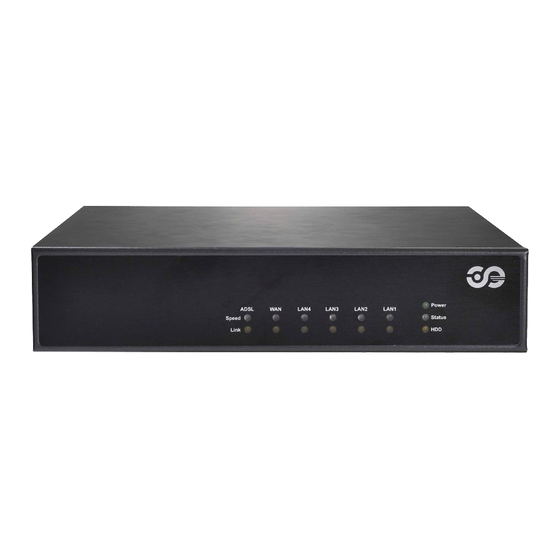
Page 6: Front Panel Features
Chapter 1 Introduction Front Panel Features F1 LED Indicators for ADSL and WAN The ADSL LED indicates the connection status of the ADSL services, whereas the WAN LED indicates the connection status of the Internet service. Speed LED (Green/Amber): Behavior Interpretation LINK/ACT (Yellow) On/Flashing... -
Page 7: Rear Panel Features
Chapter 1 Introduction Rear Panel Features R1 Antenna socket for wireless module R2 Socket for cable clip R3 DC-in Power Adapter Socket The system requires a 12V/5A power input. R4 Reset Button A Reset button is provided to reset the system without turning off the power. R5 Console Port By using suitable rollover cable (console cable), you can connect to a computer terminal for diagnostic or configuration purpose. -
Page 8: Chapter 2: Hardware Setup
Installing the Hard Disk Hardware Setup The system can accommodate one 2.5” Serial-ATA disks. Follow these steps to install a hard disk into the MR-301: Place hard disk on the hard disk tray and align the holes Preparing the Hardware Installation of the hard disk with the mounting holes of the tray. -
Page 9: Chapter 3: Motherboard Information
Chapter 3 Motherboard Information Chapter 3: Motherboard Information Block Diagram The block diagram depicts the relationships among the interfaces or modules on the motherboard. Please refer to the following figure for your motherboard’s layout design. System Power via DC-in 12V DDR2 512MB onboard memory SATA Power... -
Page 10: Board Dimension
Chapter 3 Motherboard Information Board Dimension The following diagram shows the physical dimension of the PCB board. (unit: mm) Network Application Platforms... -
Page 11: Motherboard Layout
Chapter 3 Motherboard Information Motherboard Layout The motherboard layout shows the connectors and jumpers on the board. Refer to the following picture as a reference of the pin assignments and the internal connectors. LAN Port 3 LAN Port 4 L A N P o r t 5 LAN Port 2 LAN Port 1 (LAN4) -
Page 12: Jumper Settings
Chapter 3 Motherboard Information Jumper Settings PCI-E X 1 Golden Finger Connector (PCIE2) 88F6281 JTAG Connector (J9): The Jtag is a debug port provided as a means for testing the main board and looking for possibility of field faults. It can also be used for flash writing. - Page 13 Chapter 3 Motherboard Information 12V DC Power Jack (J1): It is used for System FAN Connector(FAN1/FAN2): This 3-pin connecting the power adaptor to the board. header is for connecting the system fan. Pin No. Function Pin No. Function VCC12_IN V_12 FAN SPEED Intel Serial port UART1 Connector (J6): The 10-pin connector is for connecting RS-232 serial...
- Page 14 Chapter 3 Motherboard Information Network Application Platforms...
-
Page 15: Appendix A: Terms And Conditions
Appendix A Terms and Conditions Appendix A: RMA Service Terms and Conditions Requesting a RMA# To obtain a RMA number, simply fill out and fax the “RMA Request Form” to your supplier. Warranty Policy The customer is required to fill out the problem code as listed. - Page 16 Appendix A Terms and Conditions RMA Service Request Form When requesting RMA service, please fill out the following form. Without this form enclosed, your RMA cannot be processed. Reasons to Return: Repair(Please include failure details) RMA No: Testing Purpose Company: Contact Person: Phone No.
Need help?
Do you have a question about the MR-301 and is the answer not in the manual?
Questions and answers