
Subscribe to Our Youtube Channel
Related Manuals for FLIR PathFindIR II


Summary of Contents for FLIR PathFindIR II
- Page 1 – User Manual PathFindIR II 334-0050-00-10, version 100 Feb 2014 GlobalTestSupply www. .com Find Quality Products Online at: sales@GlobalTestSupply.com...
-
Page 2: Table Of Contents
2.2 Thermal Imaging Driver Vision Enhancement System ....4 2.2.1 PathFindIR II Camera Kit ............5 2.2.2 Installation Kit ................6 2.3 What is Thermal Imaging? ..............7 2.4 Vehicles that use PathFindIR II ............7 2.5 PathFindIR II Part Numbers .............8 3 Installation 3.1 PathFindIR II Installation ..............9 3.2 Preparation and Installation Considerations ........9... -
Page 3: Warnings And Cautions
Viewing the display may distract the driver from looking ahead and may result in an accident. The PathFindIR II thermal imaging system should not be used as a substitution for head lamps or head lamp assisted human vision during vehicle operation. -
Page 4: General Information
Great care should be used with your camera optics. They are delicate and can be damaged by improper cleaning. Refer to Chapter 5 “Caring for your PathFindIR II” on page 23. All thermal imaging systems are subject to export control. Standard NTSC (30Hz) units are subject to export restrictions and licensing by the United States Government. -
Page 5: Introduction
The above images show a comparison of typical night time driving compared to using the PathFindIR II thermal imager. The image on the left is from an ordinary camera and shows the amount of visible light as illuminated by headlights; the image on the right is a thermal image created by the PathFindIR II thermal imaging camera. -
Page 6: Thermal Imaging Driver Vision Enhancement System
Humans and other warm blooded animals offer significant thermal contrast to driving backgrounds and are easy to spot with the PathFindIR II. The system allows drivers to see without any additional lighting and provides real-time imaging at any speed. -
Page 7: Pathfindir Ii Camera Kit
PathFindIR to ECU Cable Table 2-1: Standard Camera Kit components The ECU connects to the vehicle power and interconnects the PathFindIR II to a video display. The ECU provides power to the camera, controls the camera operation and performs the image processing for pedestrian and animal detection functions. -
Page 8: Installation Kit
2 – Introduction 2.2.2 Installation Kit The optional Installation Kit includes these components: • SafetyVision Video Monitor, cables, adapters and mounting hardware • ECU mounting bracket and mounting screws • Camera mounting bracket and mounting screws Video Monitor ECU Bracket (with ECU installed) PathFinder Mounting Bracket Table 2-2: Optional Installation Kit components The Power/Video Cable is 20’... -
Page 9: What Is Thermal Imaging
Although adverse conditions such as heavy fog will affect any driver vision enhancement system, thermal imaging cameras such as the PathFindIR II have been shown to continue to provide useful information in conditions of reduced visibility, such as haze and smoke. While the PathFindIR II can assist drivers with detection of obstructions in the vehicle’s path, thermal imagers should not be... -
Page 10: Pathfindir Ii Part Numbers
When FLIR delivers a camera to a customer in the U.S. who intends to export or re-export the FLIR camera outside of the United States, whether or not the camera is integrated into another product, it is the customer’s responsibility to apply for the required export license from the appropriate department of the U.S. -
Page 11: Installation
It can be ordered as a camera module with a commercial grade cable. The PathFindIR II should be installed by an installer or dealer trained by FLIR Systems, Inc. If one is not available in your area we recommend that you use a reputable car audio/video installation shop that specializes in mobile video system integration. -
Page 12: Installation Guidelines And Precautions
The PathFindIR II must be mounted in a location where it is not obstructed by the windshield or other glass materials. Although glass is transparent to the human eye, it is opaque in the infrared spectrum. - Page 13 Installation using incorrect connections may result in system malfunction or risk of shock. The proper mating connector must be used when installing the PathFindIR II. The use of other connectors may result in damage to the camera that is not covered by the limited product warranty.
-
Page 14: Pathfindir Ii Installation
3 – Installation 3.4 PathFindIR II Installation The imager has 4 mounting holes which accept M5 x 12mm thread-forming screws (included with the standard system). Do not exceed screw insertion depth of 8-11mm and torque of 4Nm. The imager should be mounted on the exterior of the vehicle in a high position on the front of the vehicle, typically in the grille, ideally at a height of 65cm ±15cm from the ground. - Page 15 3 – Installation The alignment between the optical line of sight (LOS) and the center of the image should optimally be set by the integrator/installer as follows. • Yaw pointing error: no greater than ±2 degree (center of image to center of road), •...
-
Page 16: Ecu Installation
3 – Installation 3.5 ECU Installation In most installations, the ECU will be mounted underneath the dashboard, in relatively close proximity to the video monitor. In most installations, the ECU is secured to the vehicle with the optional ECU Mounting Bracket and the ECU Mounting Bracket is secured to the vehicle with 4 M5 x 12mm mounting screws (included). -
Page 17: Cable Connections
3.6 Cable Connections Run the PathFindIR II to ECU Cable between the camera and ECU, observing that each end of the cable can only connect to either the camera or the ECU. Connect each end of the cable making sure the connections are seated securely. -
Page 18: Mounting Assistance
The following are some general guidelines which will assist your professional service and installer with good mounting positions and connections. The PathFindIR II is a thermal imaging system. As such, it will not “see through” windows or obstructions. The system should be mounted outside the vehicle's cabin (interior) and in such a location to assure a similar driving viewing field of view as normal head lamps and human vision. -
Page 19: Getting Started
4.1 Using your PathFindIR II The PathFindIR II is easy to use, but you should take a moment to carefully read this section so you understand what is displayed on the video monitor. While the imagery on the monitor may look similar to black and white daylight video, a few tips on how to interpret the images will help you to make the most of your system. -
Page 20: Automatic Shutter
4.4 Heater Element The PathFindIR II has a built-in heating element to stabilize the window and prevent ice build-up in cold weather conditions. The heating element is automatically turned on when the temperature of the window falls below 4ºC and is tuned off when the temperature reaches 6ºC. -
Page 21: Pedestrian Detection
4 – Getting Started • Not all of the animals' legs are visible • The animal has attributes such as horns or tail, or is carrying objects such as saddle, saddlebag, collar, leash, necklace and muzzle • Animals are present in a group or herd. The algorithm most likely detects the most visible animals (which are not obstructed by others) in the group or the ones who somewhat separated from the group. -
Page 22: In Case Of Difficulty
4.6 In Case of Difficulty The PathFindIR II comes with a limited warranty from the date of purchase. Except as describe in this manual, DO NOT OPEN, MODIFY, or ALTER the PathFindIR II unit or accessories. Doing so will void any warranty and may cause system malfunction, loss of performance, fire, or bodily harm. -
Page 23: Troubleshooting
No Video, no clicking. If video is not displayed and you do not hear a “clicking” sound from the PathFindIR II, check the power inputs. The PathFindIR II runs on 6V to 16V power through the optional 20 foot standard cable power leads. - Page 24 4 – Getting Started power. Also, verify the PathFindIR II is connected to the 75 ohm input on the monitor. The image may be dim if the camera is connected to an input that requires a different impedance. The image is dark and no objects are seen.
-
Page 25: Caring For Your Pathfindir
Rinse the camera housing with low pressure fresh water to keep it clean. If the front window of the PathFindIR II gets water spots, wipe it with a clean soft cotton cloth dampened with fresh water. If the window requires further cleaning, use a soft moist cotton-based cloth with isopropyl alcohol or dish soap. -
Page 26: Temperature
The window is serviceable when the surface becomes visibly degraded and may be replaced. If you have problems do not attempt to repair the PathFindIR II unit yourself. The PathFindIR II camera is a water-tight sealed unit and can not be opened or serviced in the field. Consult your installation dealer or FLIR Systems Inc. -
Page 27: Technical Data
Dust and moisture protection:IP69 Impact protection High-impact resistant window with heating element Weather Resistance Hermetically sealed, pressurized enclosure For additional information, contact FLIR. Dimensions and Weight Dimensions Refer to the following drawings Weight less than 0.4 kg (0.88 lb.) -
Page 28: Side View
6 – Technical Data 6.1.1 Side View Feb 2014 334-0050-00-10, version 100 GlobalTestSupply www. .com Find Quality Products Online at: sales@GlobalTestSupply.com... -
Page 29: Rear View
6 – Technical Data 6.1.2 Rear View The camera mounting holes accept M5 x 12 thread-forming screws (also known as self-tapping screws). Do not exceed screw insertion depth of 8-11mm and torque of 4Nm. 334-0050-00-10, version 100 Feb 2014 GlobalTestSupply www. -
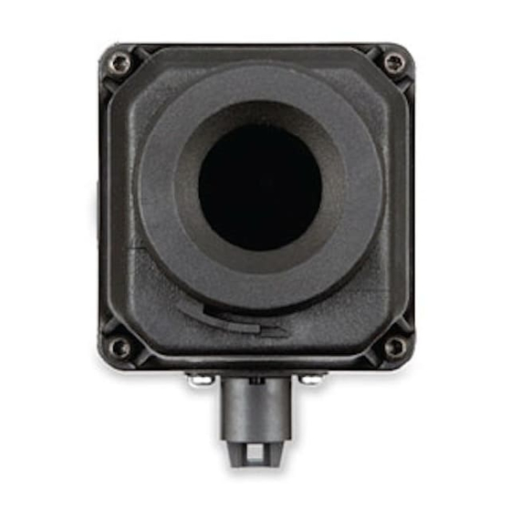
Page 30: Front View
6 – Technical Data 6.1.3 Front View Feb 2014 334-0050-00-10, version 100 GlobalTestSupply www. .com Find Quality Products Online at: sales@GlobalTestSupply.com... -
Page 31: Ecu Dimensions
6 – Technical Data 6.1.4 ECU Dimensions 334-0050-00-10, version 100 Feb 2014 GlobalTestSupply www. .com Find Quality Products Online at: sales@GlobalTestSupply.com... - Page 32 FLIR Systems, Inc. 70 Castilian Dr. Goleta, CA 93117 PH: +1.888.747.FLIR (+1.888.747.3547) Document: 334-0050-00-10 Version: 100 Date: Feb 2014 GlobalTestSupply www. .com Find Quality Products Online at: sales@GlobalTestSupply.com...
Need help?
Do you have a question about the PathFindIR II and is the answer not in the manual?
Questions and answers