
Related Manuals for RoboteQ AX3500


Summary of Contents for RoboteQ AX3500
- Page 1 AX3500 Dual Channel High Power Digital Motor Controller User’s Manual v1.7, February 1, 2005 visit www.roboteq.com to download the latest revision of this manual ©Copyright 2003-2005 Roboteq, Inc.
-
Page 2: Revision History
User’s are expected to perform their own product validation and not rely solely on data contained in this manual. AX3500 Motor Controller User’s Manual Version 1.7. February 1, 2005... -
Page 3: Table Of Contents
Connecting the controller to your PC using Roborun 18 Obtaining the Controller’s Software Revision Number 19 Exploring further 20 SECTION 2 AX3500 Motor Controller Overview 21 Product Description 21 Technical features 22 SECTION 3 Connecting Power and Motors to the Controller 25... - Page 4 Self-Test Mode 47 SECTION 5 Connecting Sensors and Actuators to Input/Outputs 49 AX3500 Connections 49 AX3500’s Inputs and Outputs 51 I/O List and Pin Assignment 52 Connecting devices to Output C 53 Connecting devices to Output D 54 Connecting Switches or Devices to Input E 55...
- Page 5 Set Accessory Outputs 93 Query Power Applied to Motors 93 Query Amps Consumed by Motors 94 Query Analog Inputs 94 Query Heatsink Temperatures 95 Query Battery Voltages 95 Query Digital Inputs 95 Read and Modify Controller Settings 96 AX3500 Motor Controller User’s Manual...
- Page 6 Using Current Limiting as Protection 120 Control Loop Description 120 PID tuning in Position Mode 122 SECTION 11 Closed Loop Speed Mode 123 Mode Description 123 Selecting the Speed Mode 123 AX3500 Motor Controller User’s Manual Version 1.7. February 1, 2005...
- Page 7 Speed 1 and 2 149 Time Base 1 and 2 149 Encoder Threshold 149 Counter Read Data Format 149 Encoder Testing and Setting Using the PC Utility 150 Encoder Module Parameters Setting 151 Exercising the Motors 152 AX3500 Motor Controller User’s Manual...
- Page 8 Connecting a Joystick 177 Viewing and Logging Data in Analog and R/C Modes 178 Loading and Saving Profiles to Disk 178 Operating the AX3500 over a Wired or Wireless LAN 178 Updating the Controller’s Software 180 Creating Customized Object Files 180 AX3500 Motor Controller User’s Manual...
- Page 9 SECTION 16 Mechanical Specifications 183 Mechanical Dimensions 183 Mounting Considerations 184 Thermal Considerations 184 Wire Dimensions 185 Weight 185 AX3500 Motor Controller User’s Manual...
- Page 10 AX3500 Motor Controller User’s Manual Version 1.7. February 1, 2005...
-
Page 11: Ax3500 Quick Start
AX3500 SECTION 1 Quick Start This section will give you the basic information needed to quickly install, setup and run your AX3500 controller in a minimal configuration. Important Safety Warnings The AX3500 is a high power electronics device. Serious damage, including fire, may occur to the unit, motors, wiring and batteries as a result of its misuse. -
Page 12: Locating Switches, Wires And Connectors
Ctrl VMot 3 x Gnd VMot Motor 2 Motor 1 FIGURE 2. Controller Rear View AX3500 Motor Controller User’s Manual Version 1.7. February 1, 2005... -
Page 13: Connecting To The Batteries And Motors
3- Connect each motor to one of the two output tabs pair. Make sure to respect the polar- ity, otherwise the motor(s) may spin in the opposite direction than expected Important Warning AX3500 Motor Controller User’s Manual... -
Page 14: Connecting The R/C Radio
In order to turn On and Off the controller without the need for a bulky and expensive switch or relay on the high current wires, the AX3500 uses a Power Control input to enable or disable the internal DC/DC converter. When left unconnected, the DC/DC converter is On. -
Page 15: Powering On The Controller
FIGURE 4. R/C connector wiring for 3 channels and battery elimination (BEC) This wiring - with the wire loop uncut - assumes hat the R/C radio will be powered by the AX3500 controller. Other wiring options are described in “R/C Operation” on page 69 of the User’s Manual. -
Page 16: Button Operation
R/C mode. Button Operation The AX3500 has three buttons: Set, Program and Reset. These buttons are not needed for normal operation, as the controller is immediately operational upon power up. The Reset button will restart the controller. This button is recessed and you will need a paper clip to press it. -
Page 17: Default Controller Configuration
The example below shows how to use the buttons to select and change the Motor Control mode from “separate” to “mixed” . See “Configuring the Controller using the Switches” on page 159 of the User’s Manual for a complete list of all the AX3500’s parameters and their meanings. -
Page 18: Connecting The Controller To Your Pc Using Roborun
• to read and plot real-time current consumption value • Save captured parameters onto disk for later analysis • to update the controller’s software AX3500 Motor Controller User’s Manual Version 1.7. February 1, 2005... -
Page 19: Obtaining The Controller's Software Revision Number
Obtaining the Controller’s Software Revision Number One of the unique features of the AX3500 is the ability to easily update the controller’s operating software with new revisions downloaded from Roboteq’s web site at www.roboteq.com. This is useful for adding features and/or improving existing ones. -
Page 20: Exploring Further
Installing new software is a simple and secure procedure, fully described in “Operating the AX3500 over a Wired or Wireless LAN” on page 178 of the User’s Manual. Exploring further By following this quick-start section, you should have managed to get your controller to operate in its basic modes within minutes of unpacking. -
Page 21: Ax3500 Motor Controller Overview
In the speed control mode, the AX3500 can operate in open loop or closed loop. In closed loop operation, actual speed measure-... -
Page 22: Technical Features
The motors are driven using high-efficiency Power MOSFET transistors controlled using Pulse Width Modulation (PWM) at 16kHz. The AX3500 power stages can operate from 12 to 40VDC and can sustain up to of controlled current, delivering up to (approximately HP) of useful power to each motor. - Page 23 • Up to 2 general purpose outputs for accessories or weapon • One 24V, 2A output • One low-level digital output (not yet implemented on AX3500) • Up to 2 general purpose digital inputs Optical Encoder Inputs • Inputs for two Quadrature Optical Encoders •...
- Page 24 • Efficient heat sinking. Operates without a fan in most applications. • 6.75” (171.5mm) long x 4.20” (106.7mm) wide • -20o to +70o C operating environment • 7 .5oz (220g) AX3500 Motor Controller User’s Manual Version 1.7. February 1, 2005...
-
Page 25: Connecting Power And Motors To The Controller
Connecting Power The AX3500 has 2 sets of Ground and Vmot Fast-on tabs and a Power Control tab: The power tabs are located at the back end of the controller. The various power tabs are identified by markings on the PCB. -
Page 26: Controller Power
FIGURE 8. Controller Rear View and Power Connector Tabs Controller Power The AX3500 uses a flexible power supply scheme that is best described in Figure 9. On this diagram, it can be seen that the Control Logic requires a stable 12V supply, while the Power Output stage that drives the motors can tolerate a very wide voltage range. - Page 27 Channel 2 MOSFET Power Stage 40V max VBatt Vmot Mot2(+) Mot2(-) FIGURE 9. Representation of the AX3500’s Internal Power Circuits TABLE 4. Effect of Power Control under various voltage conditions Power Control input is And Main Battery connected to Voltage is...
-
Page 28: Powering The Controller Using The Motor Batteries
Motor Power battery. For safety reasons, however, it is highly recommended that a way of quickly disconnecting the Motor Power be provided in the case of loss of control and all of the AX3500 safety fea- tures fail to activate Note, however, that eventually the motor batteries will get weaker and the voltage drop below the level needed for the internal DC/DC converter to properly operate. -
Page 29: Using A Backup Battery
12V backup battery connected as shown in Figure 11. Battery Power Control Motor Power Cables Wire Cables Motor2 Fuse Motor1 Controller 12V to 40V Motor Battery Controller Battery FIGURE 11. Power wiring using a two-battery system AX3500 Motor Controller User’s Manual... -
Page 30: Power Fuses
Wire Length Limits The AX3500 regulates the output power by switching the power to the motors On and Off at high frequencies. At such frequencies, the wires’ inductance produces undesirable effects such as parasitic RF emissions, ringing and overvoltage peaks. The controller has built-in capacitors and voltage limiters that will reduce these effects. -
Page 31: Electrical Noise Reduction Techniques
While the controller incorporates several cir- cuits to keep electrical noise to a minimum, additional techniques can be used to keep the noise low when installing the AX3500 in an application. Below is a list of techniques you can try to keep noise emission low: •... -
Page 32: Overvoltage Protection
Damage to the controller may occur. Overvoltage Protection The AX3500 includes a battery voltage monitoring circuit that will cause the output transis- tors to be turned Off if the main battery voltage applied on the thick red and black wires rises above 43V. - Page 33 To prevent current from flowing from the power supply into the load during normal operation, an active switch would enable the load when the voltage rises above the nominal output of the power supply. AX3500 Motor Controller User’s Manual...
- Page 34 Connecting Power and Motors to the Controller AX3500 Motor Controller User’s Manual Version 1.7. February 1, 2005...
-
Page 35: General Operation
Operation This section discusses the controller’s normal operation in all its supported operating modes. Basic Operation The AX3500’s operation can be summarized as follows: • Receive commands from a radio receiver, joystick or a microcomputer • Activate the motors according to the received command •... -
Page 36: Selecting The Motor Control Modes
General Operation Selecting the Motor Control Modes For each motor, the AX3500 supports multiple motion control modes. The controller’s fac- tory default mode is Open Loop Speed control for each motor. The mode can be changed using any of the methods described in “Programming using built-in Switches and Display”... -
Page 37: Closed Loop Speed Control
This AX3500 feature makes it possible to build ultra-high torque “jumbo servos” that can be used to drive steering columns, robotic arms, life-size models and other heavy loads. -
Page 38: Current Limit Settings
FIGURE 15. Motor with potentiometer assembly for Position operation Current Limit Settings The AX3500 has current sensors at each of its two output stages. Every 16 ms, this cur- rent is measured and a correction to the output power level is applied if higher than the user preset value. -
Page 39: Temperature-Based Current Limitation
The AX3500 also features active current limitation with a SmartAmps control algorithm. On the AX3500, this current limiting is based on the actual measured temperature of the heat sink, near the mounting point of the Power MOSFET transistors inside the controller. While the temperature is below 60oC, the controller will deliver up to 60A Continuous Amps. -
Page 40: Regeneration Current Limiting
Switches” on page 159), acceleration can be one of 6 available preset values, from very soft(0) to very quick (6). The AX3500’s factory default value is medium soft (2). When using the serial port, acceleration can be one of 24 possible values, selectable using the Roborun utility, or entering directly a value in the MCU’s configuration EEPROM. - Page 41 A quick deceleration will cause an equally large, or possibly larger, regeneration current surge. Always experiment with the lowest acceleration value first and settle for the slowest acceptable value. AX3500 Motor Controller User’s Manual...
-
Page 42: Command Control Curves
General Operation Command Control Curves The AX3500 can also be set to translate the joystick or RS232 motor commands so that the motors respond differently whether the joystick is near the center or near the extremes. The controller can be configured to use one of 5 different curves independently set for each channel. -
Page 43: Left / Right Tuning Adjustment
In others, however, it can be an inconvenience. When operat- ing in open loop speed control, the AX3500 can be configured to correct the speed in one direction versus the other by as much as 10%. Unlike the Joystick center trimming tab that... -
Page 44: Emergency Shut Down Using Controller Switches
In case of emergency, it is possibly to cause the controller to cut off the power to the motors by depressing the Program and Set buttons simultaneously as shown in the figure below. The controller will stop immediately without delay. AX3500 Motor Controller User’s Manual Version 1.7. February 1, 2005... -
Page 45: Emergency Stop Using External Switch
On to resume normal operation. Emergency Stop using External Switch An external switch can be added to the AX3500 to allow the operator to stop the control- ler’s output in case of emergency. This controller input can be configured as the “Inverted”... -
Page 46: Special Use Of Accessory Digital Inputs
General Operation Special Use of Accessory Digital Inputs The AX3500 includes two general purpose digital inputs identified as Input E and Input F . On the AX2850, input E is disabled. The location of these inputs on the DB15 connector can be found in the section “I/O List and Pin Assignment”... - Page 47 This sequence will repeat itself indefinitely until the controller is powered off or reset. While in the Self Test mode, the AX3500 will continuously send a string of characters on the RS232 output line. This string will contain 13 two-digits hexadecimal number repre- senting the 13 following operating parameters.
- Page 48 General Operation AX3500 Motor Controller User’s Manual Version 1.7. February 1, 2005...
-
Page 49: Connecting Sensors And Actuators To Input/Outputs
AX3500 Connections The AX3500 uses a set of power wires (located on the back of the unit) and a DB15 con- nector for all necessary connections. The diagram on the figure below shows a typical wir- ing diagram of a mobile robot using the AX3500 controller. - Page 50 - Tachometers (Closed loop Speed mode) Miscellaneous I/O - Potentiometers (Servo mode) Running Inverted, or emergency stop Motor Power supply wires switch Power Control wire5- Controller FIGURE 21. Typical controller connections AX3500 Motor Controller User’s Manual Version 1.7. February 1, 2005...
-
Page 51: Ax3500'S Inputs And Outputs
AX3500’s Inputs and Outputs AX3500’s Inputs and Outputs In addition to the RS232 and R/C channel communication lines, the AX3500 includes sev- eral inputs and outputs for various sensors and actuators. Depending on the selected oper- ating mode, some of these I/Os provide feedback and/or safety information to the controller. -
Page 52: I/O List And Pin Assignment
Connecting Sensors and Actuators to Input/Outputs I/O List and Pin Assignment The figure and table below lists all the inputs and outputs that are available on the AX3500. Pin1 FIGURE 22. Controller’s DB15 connector pin numbering TABLE 12. DB15 connector pin assignment... -
Page 53: Connecting Devices To Output C
Input EStop/Inv Emergency Stop or Invert Switch input *The wire colors are those used by Roboteq on our prefabricated cables. It is recom- mended you use these colors for consistency. **These connections should only be done in RS232 mode or R/C mode with radio pow- ered from the controller. -
Page 54: Connecting Switches Or Devices To Input F
00 to indicate an Off state, or 01 to indicate an On state. Connecting Switches or Devices to EStop/Invert Input This input is used to connect various switches or devices depending on the selected con- troller configuration. AX3500 Motor Controller User’s Manual Version 1.7. February 1, 2005... -
Page 55: Connecting Position Potentiometers To Analog Inputs
This feature is useful in order to create very powerful servos as proposed in the figure below: Position Feedback Potentiometer Gear box FIGURE 26. Motor and potentiometer assembly for position servo operation AX3500 Motor Controller User’s Manual... -
Page 56: Connecting Tachometer To Analog Inputs
2.5V midpoint value it is recommended to add a 100 ohm trimmer on the voltage divider. With this circuitry, the controller will see 2.5V at its input when the tachometer is stopped, 0V when running in full reverse, and +5V in full forward. AX3500 Motor Controller User’s Manual Version 1.7. February 1, 2005... -
Page 57: Connecting External Thermistor To Analog Inputs
Using external thermistors, the AX3500 can be made to supervise the motor’s tempera- ture and adjust the power output in case of overheating. Connecting thermistors is done according to the diagram show in Figure 31. The AX3500 is calibrated using a 10kOhm Negative Coefficient Thermistor (NTC) with the temperature/resistance characteristics shown in the table below. -
Page 58: Using The Analog Inputs To Monitor External Voltages
RS232 port. The recommended schematic is shown in Figure 33. AX3500 Motor Controller User’s Manual Version 1.7. February 1, 2005... -
Page 59: Connecting User Devices To Analog Inputs
5V, thus providing limited protection. The value of the analog inputs can be read through the controller’s RS232 port. +5V 14 Input Ana 1 11 47kOhm or Ana 2 10 10kOhm 47kOhm Ground 5 FIGURE 32. AX3500 Analog Input equivalent circuit AX3500 Motor Controller User’s Manual... -
Page 60: Internal Voltage Monitoring Sensors
Measured Internal Volts = 28.5 * Read Value / 256 Internal Heatsink Temperature Sensors The AX3500 includes temperature sensors near the transistor of each of the two output stages. These sensors are used to automatically reduce the maximum Amps that the controller can deliver as it overheats. -
Page 61: Temperature Conversion C Source Code
150; else LoTemp = i * 5 - 40; HiTemp = LoTemp + 5; lobound = TempTable[i]; hibound = TempTable[i+1]; temp = LoTemp + (5 * ((AnaValue - lobound)*100/ (hibound - lobound)))/100; return temp; AX3500 Motor Controller User’s Manual... - Page 62 Connecting Sensors and Actuators to Input/Outputs AX3500 Motor Controller User’s Manual Version 1.7. February 1, 2005...
-
Page 63: Normal And Fault Condition Led Messages
LED display during normal operation and fault conditions. Use of the LED Display The AX3500 uses a single 7-segment LED display to report a number of operating or fault conditions. The type of reported information depends on the controller’s operating context: During normal motor operation: •... -
Page 64: Motor Direction Status
Motor 1 Motor 2 Comment Is also displayed when con- troller is active with a 0 com- mand on each channel (i.e. motors at speed 0) Forward Forward Reversed Forward AX3500 Motor Controller User’s Manual Version 1.7. February 1, 2005... -
Page 65: Fault Messages
Dead-man switch is acti- vated (see page 46) Fault Messages The AX3500 uses the LED display to report fault conditions. When these messages are displayed, the motors are normally stopped. No Control This message is displayed in the R/C mode to indicate that no valid radio signal has been detected at its inputs, or that radio signal has been lost. -
Page 66: Emergency Stop
LED will display one of the patterns described in Table 14. The cycle will repeat indefinitely until the controller is powered Off or reset. = Software version 1.7 = Software version 2.0.c FIGURE 38. Example of Software revision number display AX3500 Motor Controller User’s Manual Version 1.7. February 1, 2005... -
Page 67: R/C Operation
Mode Description The AX3500 can be directly connected to an R/C receiver. In this mode, the speed or posi- tion information is contained in pulses whose width varies proportionally with the joysticks’ positions. The AX3500 mode is compatible with all popular brands of R/C transmitters. A third R/C channel can be used to control the On/Off state of two outputs that may be con- nected to electrical accessories (valves, lights, weapons,...) -
Page 68: Selecting The R/C Input Mode
Motor Channels R/C Receiver R/C Receiver Battery (Optional) 1 or 2 user accessory (Optional) "Emergency Stop" or "Inverted" Switch (Optional) • a 12V to 40V to Main Battery AX3500 Motor Controller User’s Manual Version 1.7. February 1, 2005... -
Page 69: Connector I/O Pin Assignment (R/C Mode)
TABLE 15. Connector pin-out in R/C mode Input or Number Signal Output Description Output C Output 2A Accessory Output C (same as pin 9) RS232 Out Output Optional. Used for Data Logging R/C Channel 1 Input Channel 1 input pulse (isolated) AX3500 Motor Controller User’s Manual... -
Page 70: R/C Input Circuit Description
Emergency Stop or Invert Switch input R/C Input Circuit Description The AX3500 includes an optical isolation barrier on the Channel 1 and Channel 2 R/C radio inputs. Figure 41 shows an electrical representation of the R/C input circuit. The right side is powered from the controller’s batteries. -
Page 71: Supplied Cable Description
FIGURE 41. AX3500 R/C Input equivalent circuit Supplied Cable Description The AX3500 is delivered with a custom cable that can easily be adapted to operate in any of the supported isolated and non isolated modes. The figures below show the cable and its wiring diagram FIGURE 42. -
Page 72: Cabling To R/C Receiver Using Full Opto-Isolation
Note: Only one set of black and red (battery) wires needs to be brought Pin 1 to the connector. Cut loop FIGURE 44. Channel 1 & 2 wiring using external battery and full optical isolation AX3500 Motor Controller User’s Manual Version 1.7. February 1, 2005... -
Page 73: Cabling To R/C Receiver With Partial Opto-Isolation
This wiring option should be considered only when the Accessory R/C channel (Channel 3) is required. Since Channel 3 is directly connected to the AX3500’s microcontroller without opto coupler, it is necessary to connect the radio and controller grounds together to create a common ground reference for the signal. -
Page 74: Powering The Radio From The Controller
R/C radio. The wire loop is used to bring the controller’s power to the the radio as well a for powering the optocoupler stage. Figure 48 below shows the connec- tor wiring necessary to do this. Figure 49 shows the equivalent electrical diagram. AX3500 Motor Controller User’s Manual Version 1.7. February 1, 2005... - Page 75 5.5V. Notice that in this configuration, the controller’s +5V power and ground are connected to the floating (opto-isolated) R/C power inputs so that now the radio and the controller are no longer optically isolated. AX3500 Motor Controller User’s Manual...
-
Page 76: Operating The Controller In R/C Mode
R/C models remote controls. The speed or position information is communicated to the AX3500 by the width of a pulse from the R/C receiver: a pulse width of 1.0 millisec- ond indicates the minimum joystick position and 2.0 milliseconds indicates the maximum joystick position. -
Page 77: Reception Watchdog
“safe condition” value) when radio communication is lost. This signal will be inter- preted by the AX3500 as a valid command and the controller will remain active. To benefit from the AX3500’s radio detection function, you will need to disable the your PCM radio watchdog. -
Page 78: Joystick Deadband Programming
“d” parameter using one of the three methods described in the chapter “Configuring the Controller using the Switches” on page 159. The AX3500 has 8 preset deadband val- ues coded 0 to 7 . The value 0 disables the deadband. Other values select a deadband according to the table below. -
Page 79: Command Control Curves
To compensate for this, the AX3500 can be made to give one side up to 10% more power than the other at the same settings. This capability is described in detail in “Left / Right Tuning Adjustment”... -
Page 80: Automatic Joystick Calibration
To reset the controller to factory default or to program the joystick’s positions using numer- ical values, see “Configuring the Controller using the Switches” on page 159 and “Using the Roborun Configuration Utility” on page 165. AX3500 Motor Controller User’s Manual Version 1.7. February 1, 2005... -
Page 81: Data Logging In R/C Mode
On before entering joystick calibration. Data Logging in R/C Mode While in R/C Mode, the AX3500 will continuously send a string of characters on the RS232 output line. This string will contain 12 two-digits hexadecimal number representing the 12 following operating parameters. - Page 82 To AX2550 RX Data RS232 Data Out R/C Ch 1 R/C Ch 2 R/C GND R/C +5V FIGURE 55. Modified R/C cable with RS232 output for data logging to a PDA AX3500 Motor Controller User’s Manual Version 1.7. February 1, 2005...
-
Page 83: Serial (Rs-232) Controls And Operation
This section describes the communication settings and the commands accepted by the AX3500 in the RS232 mode of operations. This information is useful if you plan to write your own controlling software on a PC or microcomputer. These commands will also allow you to send commands manually using a terminal emulation program. -
Page 84: Connector I/O Pin Assignment (Rs232 Mode)
Must be wired to pin 13 or pin 5 +5V In Power Input Must be wired to pin 14 Input E Input Accessory input E - (Not available on AX3500) Output C Output 2Amp Accessory Output C (same as pin 1) Speed/Pos/T 2 Analog in... -
Page 85: Cable Configuration
FIGURE 57 . PC to AX3500 RS232 cable/connector wiring diagram Extending the RS232 Cable The AX3500 is delivered with a 4 foot cable adapter which may be too short, particularly if you wish to run and monitor the controller inside a moving robot. -
Page 86: Communication Settings
The controller can easily be connected to a PC in order to manually exercise its capabilities. Simply connect the supplied cable to the AX3500 on one end (DB-15 connector) and to a free COM port on the other end (DB-9 connector). -
Page 87: Entering Rs232 From R/C Or Analog Mode
OK prompt FIGURE 59. Power-on message appearing on Hyperterm On the AX3500, AX2850, or AX2550 with an Encoder module, this first prompt is immedi- ately followed by a second one send by the MCU dedicated to the Encoder function: RoboEnc v1.7 02/01/05... -
Page 88: Rs232 Mode If Default
RS232 Commands Set AX3500 commands and queries are composed of a series of 2 or 4 characters followed by the “enter” (carriage return) code. The controller will send back (echo) every character it is receiving. By checking that the returned character is the same as the one sent, it is possible to verify that there has been no error in communication. -
Page 89: Set Accessory Outputs
This query is most useful for providing feedback to a microcontroller commanding the con- troller. The hexadecimal format is intended to be deciphered by a microcontroller. When exercising the controller manually, you may use the Decimal to Hexadecimal conversion table on page 103. AX3500 Motor Controller User’s Manual... -
Page 90: Query Amps Consumed By Motors
Decimal to Hexadecimal conversion table on page 103. Important Notice On the AX3500, the number returned by the ?a command must be divided by two to obtain the actual Amps value Query Analog Inputs... -
Page 91: Query Heatsink Temperatures
Figure 35 on page 63 shows this correlation. Sample conversion software code is available from Roboteq upon request. The values are unsigned Hexadecimal numbers ranging from 0 to 255. The lowest read value represents the highest temperature. -
Page 92: Read And Modify Controller Settings
- if error Where mm= parameter number nn= new parameter value Examples: ^02 03 Store 03 into parameter 2 Notes: All parameters and values are expressed with 2 hexadecimal digits AX3500 Motor Controller User’s Manual Version 1.7. February 1, 2005... -
Page 93: Apply Parameter Changes
Character Echo At the most fundamental level, the AX3500 will echo back to the PC or Microcontroller every valid character it has received. If no echo is received, one of the following is occur- ring: •... -
Page 94: Command Error
The RS232 watchdog is automatically enabled when entering the RS232 mode from the RC or from the Analog modes (see “Entering RS232 from R/C or Analog mode” on page 91) AX3500 Motor Controller User’s Manual Version 1.7. February 1, 2005... -
Page 95: Rs232 Accessible Parameter Table
RS232 Accessible Parameter Table RS232 Accessible Parameter Table Table 18 below lists the complete set of configuration parameters that may be accessed and changed using RS232 commands. TABLE 18. AX3500 Configuration parameters accessible through RS232 Param Active Description Allowed Values (default) - Page 96 Serial (RS-232) Controls and Operation TABLE 18. AX3500 Configuration parameters accessible through RS232 Param Active Description Allowed Values (default) after pages Input switch func- Bits 0 to 3 contain the EStop/Inv input Reset tion operating mode or ^FF 0 = causes emergency stop...
-
Page 97: Automatic Switching From Rs232 To Rc Mode
RC mode. This would typically used to let a user to take over the control of a robotic vehicle upon computer problem. While the AX3500 can operate in either RC Radio or RS232 mode, the RS232 Data Input and RC Pulse Input 1 share the same pin on the connector. External hardware is therefore needed to switch this pin from the RS232 source or the RC Radio. -
Page 98: Analog And R/C Modes Data Logging String Format
The data may be captured using a PC connected via an RS232 cable or wireless modem, or into a PDA installed in the actual robot. Details on how to wire the AX3500 Motor Controller User’s Manual Version 1.7. February 1, 2005... -
Page 99: Data Logging Cables
Characters are sent by the controller at the rate of one every 8ms. A complete string is sent in 224ms. Data Logging Cables The wring diagrams shown in the figures below describe an easy-to-assemble cable assembly for use to create insertion points where to connect the PC for debug and data AX3500 Motor Controller User’s Manual... -
Page 100: Decimal To Hexadecimal Conversion Table
Table 19 to do the translation. Note that the table only shows numbers for 0 to 127 decimal (00 to 7F hexadecimal). The AX3500’s speed commands are within this range. Table 20 shows the conversion values for numbers between 128 and 255 (unsigned) and between -1 and -128 (signed) TABLE 19. - Page 101 TABLE 19. 0 to +127 signed or unsigned decimal to hexadecimal conversion table TABLE 20. +128 to 255 unsigned and -1 to -128 signed decimal to hexadecimal conversion table UDec UDec UDec UDec -128 -127 -126 -125 -124 -123 -122 -121 AX3500 Motor Controller User’s Manual...
- Page 102 TABLE 20. +128 to 255 unsigned and -1 to -128 signed decimal to hexadecimal conversion table UDec UDec UDec UDec -120 -119 -118 -117 -116 -115 -114 -113 -112 -111 -110 -109 -108 -107 -106 -105 -104 -103 -102 -101 -100 AX3500 Motor Controller User’s Manual Version 1.7. February 1, 2005...
-
Page 103: Analog Control And Operation
This section describes how the motors may be operated using analog voltage commands. Mode Description The AX3500 can be configured to use a 0 to 5V analog voltage, typically produced using a potentiometer, to control each of its two motor channels. The voltage is converted into a digital value of -127 at 0V, 0 at 2.5V and +127 at 5V. -
Page 104: Connector I/O Pin Assignment (Analog Mode)
Output D Output Not available on AX3500 Ground Out Power Controller ground (-) +5V Out Power Output +5V Power Output (100mA max.) Switch Input Input Emergency Stop or Invert Switch input AX3500 Motor Controller User’s Manual Version 1.7. February 1, 2005... -
Page 105: Connecting To A Voltage Source
(low impedance) so that it is not affected by these resistors. Connecting a Potentiometer Figure 64 shows how to wire a potentiometer to the AX3500. By connecting one end to ground and the other to 5V, the potentiometer acts as an adjustable voltage divider. The voltage will thus vary from 0V when the tap is at the minimum position and to 5V when the tap is at the maximum position. -
Page 106: Selecting The Potentiometer Value
If the value of the potentiometer is high, then the two 47K resistors built into the controller will distort the reading. The effect is minimal on a 10K potentiometer but is significant on a AX3500 Motor Controller User’s Manual Version 1.7. February 1, 2005... -
Page 107: Analog Deadband Adjustment
Changing the deadband parameter can be done using the controller’s switches (see “Con- figuring the Controller using the Switches” on page 159) or the Roborun utility on a PC (see “Loading, Changing Controller Parameters” on page 168). AX3500 Motor Controller User’s Manual... -
Page 108: Power-On Safety
(2.5V on each input). Data Logging in Analog Mode While in Analog Mode, the AX3500 will continuously send a string of characters on the RS232 output line. This string will contain 13 two-digits hexadecimal number representing the following operating parameters. - Page 109 FIGURE 67 . Modified Analog cable with RS232 output data logging for PC DB9 Male DB15 Male To PDA To AX2500 RX Data RS232 Data Out Ana Ch2 Ana Ch1 FIGURE 68. Modified Analog cable with RS232 output data logging for PDA AX3500 Motor Controller User’s Manual...
- Page 110 Analog Control and Operation AX3500 Motor Controller User’s Manual Version 1.7. February 1, 2005...
-
Page 111: Closed Loop Position Mode
Closed Loop SECTION 10 Position Mode This section describes the AX3500 Position mode, how to wire the motor and position sen- sor assembly, and how to tune and operate the controller in this mode. Mode Description In this mode, the axle of a geared down motor is coupled to a position sensor that is used to compare the angular position of the axle versus a desired position. -
Page 112: Position Sensor Selection
Closed Loop Position Mode Position Sensor Selection The AX3500 may be used with the following kind of sensors: • Potentiometers • Hall effect angular sensors • Optical Encoders The first two are used to generate an analog voltage ranging from 0V to 5V depending on their position. -
Page 113: Potentiometer Wiring
Using the Encoder Module, ” on page 131 for a detailed discussion. Sensor and Motor Polarity The sensor polarity (i.e. which rotation end produces 0 or 5V) is related to the motor’s polarity (i.e. which direction the motor turns when power is applied to it). AX3500 Motor Controller User’s Manual... - Page 114 11. Move the sensor back to the center point to stop the motor. Cut the power if you feel you are losing control. 12. If the polarity was wrong, invert it and repeat steps 8 to 11. 13. Tighten the sensor. Important Safety Warning AX3500 Motor Controller User’s Manual Version 1.7. February 1, 2005...
-
Page 115: Adding Safety Limit Switches
Note that the current will flow though the diode only for the short time needed for the motor to move away from the limit switches. Motor AX2550 FIGURE 71. Safety limit switches interrupting power to motors AX3500 Motor Controller User’s Manual... -
Page 116: Using Current Limiting As Protection
Closed Loop Position Mode The second method uses the AX3500’s Emergency Stop input to shut down the controller if any of the limit switches is tripped. Figure 72 shows the wiring diagram used in this case. Each of the limit switches is a Normally Open switch. Two of these switched are typ- ically required for each motor. - Page 117 Proportional component alone. Only a very small amount of Integral Gain is typically required in this mode. AX3500 Motor Controller User’s Manual...
-
Page 118: Pid Tuning In Position Mode
Note that the AX3500 uses one set of Proportional, Integral and Differential Gains for both motors and therefore assumes that similar motors, mechanical assemblies and loads are present at each channel. -
Page 119: Closed Loop Speed Mode
If the speed changes because of changes in load, the control- ler automatically compensates the power output. This mode is preferred in precision motor control and autonomous robotic applications. The AX3500 incorporates a full-featured Proportional, Integral, Differential (PID) control algorithm for quick and stable speed control. Selecting the Speed Mode... -
Page 120: Using Optical Encoder For Speed Feedback (Ax2850 Only)
Proper mounting of the speed sensor is critical for an effective and accurate speed mode operation. Figure 74 shows a typical motor and tachometer or encoder assembly. Tachometer or Optical Encoder (AX2850 & AX3500 only) Speed Feedback FIGURE 74. Motor + tachometer assembly needed for Close Loop Speed mode Tachometer wiring The tachometer must be wired so that it creates a voltage at the controller’s analog input... -
Page 121: Speed Sensor And Motor Polarity
CHA and ChB outputs 10. If a tachometer is used, proceed to calibrate the Max Closed Loop speed. 11. Set the controller parameter to the desired Closed Loop Speed mode using the Roborun utility AX3500 Motor Controller User’s Manual... -
Page 122: Adjust Offset And Max Speed
Emergency Stop is activated. Control Loop Description The AX3500 performs the Closed Loop Speed mode using a full featured Proportional, Inte- gral and Differential (PID) algorithm. This technique has a long history of usage in control... -
Page 123: Pid Tuning In Speed Mode
Proportional, Integral and Differential gains and another screen for running and monitor- ing the motors. Run first the motor with the preset values. Then experiment different val- ues until a satisfactory behavior is found. AX3500 Motor Controller User’s Manual... - Page 124 Note that the AX3500 uses one set of Proportional Integral and Differential Gains for both motors and therefore assumes that similar motors, mechanical assemblies and loads are present at each channel.
-
Page 125: Installing, Connecting And Using The Encoder Module
Connecting and Using the Encoder Module This section describes the Encoder input module that is built into the AX3500. Optical Incremental Encoders Overview Optical incremental encoders are a mean for capturing speed and travelled distance on a motor. Unlike absolute encoders which give out a multi-bit number (depending on the reso- lution), incremental encoders output pulses as they rotate. -
Page 126: Recommended Encoder Types
The choice of encoder resolution is very wide and is constrained by the module’s maxi- mum pulse count at the high end, and measurement resolution for speed at the low end. AX3500 Motor Controller User’s Manual Version 1.7. February 1, 2005... -
Page 127: Connecting The Encoder
Using multi-level signaling, it is also pos- sible to share the quadrature inputs with limit switches. The figure and table below describes the connector and its pin assignment. FIGURE 79. Encoder connector AX3500 Motor Controller User’s Manual... -
Page 128: Motor - Encoder Polarity Matching
In Figure 85, the encoders are connected directly to the Channel A and B inputs. In this case, because the encoder’s 0 level is below 0.5V, it will cause a Switch Detection condi- tion which should be ignored. AX3500 Motor Controller User’s Manual Version 1.7. February 1, 2005... -
Page 129: Wiring Optional Limit Switches
If limit switches are needed by the application, additional circuitry is required in order to create a multi-level signal that share the encoder and the switch information. shows the electrical diagram of the required wiring. AX3500 Motor Controller User’s Manual... -
Page 130: Using The Encoder Module To Measure Distance
The counters can be read and set using the commands described in “RS232 Encoder Command Set” on page 142. AX3500 Motor Controller User’s Manual Version 1.7. February 1, 2005... -
Page 131: Using The Encoder To Measure Speed
A measured speed value of 1 correspond to the following measurable min. actual RPM val- RPM at Min. Measurable Speed Value = 1 * 58593.75 / ((4 + 1) * 200) = 58.6 RPM The Roborun Utility automatically makes the above calculations when setting up the encoder. AX3500 Motor Controller User’s Manual... -
Page 132: Using The Encoder To Track Position
If computed distance is larger than +127 , then reported distance is +127 Destination= 50,050 Counter= 50,000 distance at divider FIGURE 83. Small distance computation example Destination= 50,000 Counter= 45,000 distance at divider FIGURE 84. Large distance computation example Important Notice AX3500 Motor Controller User’s Manual Version 1.7. February 1, 2005... -
Page 133: Rs232 Communication With The Encoder Module
“home” position and reset the counters at that reference point. RS232 Communication with the Encoder Module The AX3500 contains its own Microcontroller and firmware in Flash. The Encoder’s MCU communicates with the one on the main board of the controller. During normal operations, the two MCUs exchange information as needed, invisibly to the user. -
Page 134: Rs232 Encoder Command Set
= counter value using 1 to 8 Hex digits. See “Counter Read Data Format” on page 149 for format description Examples: Read Encoder 1, Absolute Read Encoder 2, Relative AX3500 Motor Controller User’s Manual Version 1.7. February 1, 2005... -
Page 135: Set/Reset Encoder Counters And Destination Registers
Time Base. See “Using the Encoder to Measure Speed” on page 139 for a detailed discussion. Syntax: ?z or ?Z Reply: Where: nn = speed 1 value mm = speed 2 value AX3500 Motor Controller User’s Manual... -
Page 136: Read Distance
This query will cause the controller to return the status of the four optional Encoder limit switches. The returned value is a two-digit (8-bit) Hexadecimal number of which the each of the 4 least significant bit represents one of the hardware switches. AX3500 Motor Controller User’s Manual Version 1.7. February 1, 2005... -
Page 137: Read / Modify Encoder Module Registers And Parameters
256 memory locations, a small number of these location should ever be read or altered. Parameter address and returned values are two digit Hexadecimal numbers (8-bit). Important Note Command character has been changed from “$” to “*” starting in version 1.7 of the controller firmware. AX3500 Motor Controller User’s Manual... - Page 138 Counter Read/Write Mailbox LSB (bits 7 to 0) Counter 1 MSB (bits 31 to 24) Counter 1 (bits 23 to 16) 4 bytes Limited Counter 1 (bits 15 to 8) Counter 1 LSB (bits 7 to 0) AX3500 Motor Controller User’s Manual Version 1.7. February 1, 2005...
-
Page 139: Register Description
Do not alter any other area locations as this may cause program execution failure inside the encoder module. Register Description Encoder Hardware ID code Returns a 4-bit number identifying the encoder module hardware version and the status of two on-board jumpers. For Roboteq use only. AX3500 Motor Controller User’s Manual... -
Page 140: Switch Status
These registers contain a signed 8-bit value (-127 to +127) that represents the distance between the current counter position and the desired destination. This number is com- puted using a formula described in section “Using the Encoder to Track Position” on page 140. AX3500 Motor Controller User’s Manual Version 1.7. February 1, 2005... -
Page 141: Speed 1 And 2
Encoder Module to Measure Distance” on page 138 for a detailed description. Encoder Threshold This register is not used in the AX3500 as threshold is fixed at 2.5V in that model. See “Voltage Levels, Thresholds and Limit Switches” on page 136 for a detailed description. -
Page 142: Encoder Testing And Setting Using The Pc Utility
Once the utility is up and running and the controller found and identified, click on the “Encoder” tab to bring up the Encoder configuration and setup screen show in Figure 90 below. FIGURE 86. Encoder setup and test screen on Roborun AX3500 Motor Controller User’s Manual Version 1.7. February 1, 2005... -
Page 143: Encoder Module Parameters Setting
The Encoder module has 4 programmable parameters: Two Time Bases (one for each encoder), a Divider for computing relative distance, and the voltage threshold for discern- ing a 0 or 1 level at the encoder’s output. In the case of the AX3500, the threshold is fixed at 2.5V and cannot be changed. -
Page 144: Exercising The Motors
(see “Updating the Controller’s Software” on page 180). Then select the new soft- ware file to download. The file’s content automatically identifies it as software for the Encoder MCU rather that the Controller’s MCU. AX3500 Motor Controller User’s Manual Version 1.7. February 1, 2005... - Page 145 Updating the Encoder Software AX3500 Motor Controller User’s Manual...
- Page 146 Installing, Connecting and Using the Encoder Mod- AX3500 Motor Controller User’s Manual Version 1.7. February 1, 2005...
-
Page 147: Rc Pulses Output
RC Pulse Output Overview The AX3500 is equipped with an RC pulse output port for driving RC servos or additional Roboteq controllers. Up to 8 devices can be controlled in this way by a single AX3500, as shown in Figure 91. -
Page 148: Connector Location And Pinout
FIGURE 92. RC Output Connector Connecting Servos and Slave Controllers Special care must be used when connecting the AX3500 to servos or to slave control- ler.The 5V power output has very limited current driver capability of approximately 100mA for all 8 channels and can therefore be used to drive directly, as shown in Figure 93, only the most efficient servos with very little load. -
Page 149: Pulse Timing Information
Pulse Timing Information Note: When attempting to supply power from the AX3500 to a standard or heavy duty servo, current surges every time the servo attempts to move will cause the controller to reset. When connecting the AX3500 to other Roboteq slave controllers, care must be taken that the 5V outputs that is present on the Master’s RC Output connector, and on the 5V output... -
Page 150: Rs232 Commands
Hexadecimal numbers (8-bit). Read parameter Syntax: Reply: Where mm= address location of RC Register DD= current position Example: Read value of parameter at address hex A4 Controller replies, value is 7F AX3500 Motor Controller User’s Manual Version 1.7. February 1, 2005... -
Page 151: Rc Channel Testing Using The Pc Utility
Utility” on page 165. Once the utility is up and running and the controller found and identified, click on the “RC Out” tab to bring up the test screen show in Figure 100 below. AX3500 Motor Controller User’s Manual... - Page 152 From this screen, moving the cursor on any of the 8 sliders will cause the PC to send RC positioning command to the controller via the RS232 port to its respective output. AX3500 Motor Controller User’s Manual Version 1.7. February 1, 2005...
-
Page 153: Configuring The Controller Using The Switches
Controller using the Switches The AX3500 Speed Controller can be programmed to operate in many modes using a simple set-up procedure. Two buttons and a 7-segment LED display let the user examine and change these settings. Alternatively, the controller may be pro- grammed using a PC connected to the AX3500 controller through the RS232 serial communication port. -
Page 154: Entering Programming Mode
After 10 seconds, the controller will enter the programming mode and flash a letter repre- senting the first parameter in the list, followed by its numerical value. AX3500 Motor Controller User’s Manual Version 1.7. February 1, 2005... -
Page 155: Changing Parameters
(this will cause all parameters you have changed to be restored to their default values as well) The Joystick calibration operation is fully described in the R/C mode chapter. See “Left / Right Tuning Adjustment” on page 43. AX3500 Motor Controller User’s Manual... -
Page 156: Restoring Factory Defaults
Configuring the Controller using the Switches Restoring factory defaults Should you, for any reason, require to reset the AX3500 controller to its factory defaults value, press and hold the Program and Set button together for 10 seconds while resetting the controller. All parameters, including Joystick limits will be reset to their default values shown in the “Programmable Parameters List”... - Page 157 0 = very slow page 40 1 = slow (2) = medium (default) 3 = medium 4 = fast 5 = fastest Acceleration may be set with a finer resolu- tion using the PC utility AX3500 Motor Controller User’s Manual...
- Page 158 ** Values are in hexadecimal numbers where the decimal values 10, 11, 12... 15 are repre- sented with the letters A, B, C... F . *** Deadband percent values shown are for R/C mode. For analog deadband values, see page 111. AX3500 Motor Controller User’s Manual Version 1.7. February 1, 2005...
-
Page 159: Using The Roborun Configuration Utility
Configuration Utility A PC based Configuration Utility is available, free of charge, from Roboteq. This pro- gram makes configuring and operating the AX3500 much more intuitive by using pull-down menus, buttons and sliders. The utility can also be used to update the controller’s software in the field as described in “Updating the Controller’s Soft-... -
Page 160: Connecting The Controller To The Pc
Upon powering On, the controller will display “no ctrl” if configured in the R/C mode or a steady pattern if configured in the RS232 mode. AX3500 Motor Controller User’s Manual Version 1.7. February 1, 2005... -
Page 161: Roborun Frame, Tab And Menu Descriptions
1- Program Revision Number This is the revision and date of the Roborun utility. It is recommended that you always ver- ify that you have the latest revision of the utility from Roboteq’s web site at www.roboteq.com 2- Controller and Communication Link Information This frame will automatically be updated with an indication that a free communication port was found and opened by the utility. -
Page 162: Getting On-Screen Help
You can read the controller’s setting in the PC at any other time by pressing the “Load from Controller” button. After changing a parameter, you must save it to the controller manually by pressing the “Save to Controller” button. AX3500 Motor Controller User’s Manual Version 1.7. February 1, 2005... -
Page 163: Controls Settings
3- Input Command Adjustment These pull down menus will let you select one of five conversion curves on each of the input command values. See “Command Control Curves” on page 42. 4- Emergency Stop or Invert Switch Select AX3500 Motor Controller User’s Manual... -
Page 164: Power Settings
This slider will let you select one of seven preset acceleration values. The label on the right shows a numerical value which represents the amount of time the controller will take to accelerate a motor from idle to maximum speed. See “Programmable Acceleration” on page 40. AX3500 Motor Controller User’s Manual Version 1.7. February 1, 2005... -
Page 165: Analog Or R/C Specific Settings
They are also useful for viewing the stored values after an automatic joystick calibration sequence. See “Joystick Calibration” on page 81 and “Automatic Joystick Calibration” on page 82. AX3500 Motor Controller User’s Manual... -
Page 166: Closed Loop Parameters
Important Notes: Most but not all configuration parameters can be updated using the switches. The print command will automatically use your default printer. No print setup box will be displayed. AX3500 Motor Controller User’s Manual Version 1.7. February 1, 2005... -
Page 167: Optical Encoder Operation
This feature is particularly useful during development as you will be able to visualize, in real-time, the robot’s Amps consumption and other vital statistics dur- ing actual operating conditions. Figure 109 shows the Run Screen and its numerous buttons and dials. AX3500 Motor Controller User’s Manual... - Page 168 The Amps field reports the current measured at each channel. The Peak Amps field will store the highest measured Amp value from the moment the program began or from when the peak was reset using the Clr Peak button. AX3500 Motor Controller User’s Manual Version 1.7. February 1, 2005...
- Page 169 6- Input Status and Output Setting This section includes two check boxes and three color squares. The check marks are used to activate either of the controller’s two outputs. The color blocks reflect the status of the AX3500 Motor Controller User’s Manual...
-
Page 170: Logging Data To Disk
The file format is a regular text file with each parameter saved one after the other, separated by a coma. The file extension automatically defaults to .csv (coma separated values) so that the data can be imported directly into Microsoft Excel. The first AX3500 Motor Controller User’s Manual Version 1.7. February 1, 2005... -
Page 171: Connecting A Joystick
A joystick test program name “Joytest” is automatically installed in your Start menu when installing the Roborun utility. This program may be used to further verify that the joystick is properly installed in the PC and is fully operational. AX3500 Motor Controller User’s Manual... -
Page 172: Viewing And Logging Data In Analog And R/C Modes
The data may be captured using a PC connected to the controller via an RS232 cable or wireless modem. When wired for R/C or Analog controls, the AX3500 will not be able to receive commands from the PC and the Roborun software will not recognize the controller as being present. - Page 173 Operating the AX3500 over a Wired or Wireless LAN To operate over the network two computers are required, as show in Figure 110 below. The top computer is connected to the controller via its COM port. Both computers are con- nected to a TCP/IP network.
-
Page 174: Updating The Controller's Software
Using the Roborun Configuration Utility Updating the Controller’s Software The AX3500’s operating software can be easily upgraded after it has left the factory. This feature makes it possible to add new features and enhance existing ones from time to time. - Page 175 Select the latest official controller firmware issued by Roboteq Select the profile file that you created and saved earlier Select a revision letter. This letter will be added at the end of Roboteq’s own version identity number. Click on the Create button and save the new customized object file...
- Page 176 Using the Roborun Configuration Utility AX3500 Motor Controller User’s Manual Version 1.7. February 1, 2005...
-
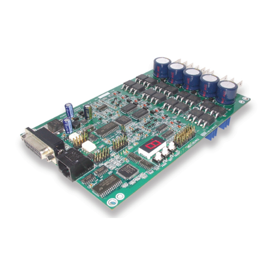
Page 177: Mechanical Specifications
This section details the mechanical characteristics of the AX3500 controller. Mechanical Dimensions The AX3500 is delivered as an assembled and tested Printed Circuit Board. The board includes connectors for direct connection to the Optical Encoders and to the Radio, Joy- stick or microcomputer on one side. -
Page 178: Mounting Considerations
0.6" (15mm) or longer spacer FIGURE 115. Use spacers to provide clearance for heatsink The AX3500 uses no jumpers and includes no loose parts or wires. Consequently, it will be able to run reliably in severe shock and vibration environment. -
Page 179: Wire Dimensions
Wire Dimensions The AX3500 uses Fast-on tabs for the power connections to the batteries and motors. These connectors are rated to support the controller’s maximum specified current. Mating connectors are widely available and use crimping techniques to secure the electrical wires. - Page 180 Mechanical Specifications AX3500 Motor Controller User’s Manual Version 1.7. February 1, 2005...
Need help?
Do you have a question about the AX3500 and is the answer not in the manual?
Questions and answers