Table of Contents
Advertisement
2x150A
High Performance
Dual Channel
Forward/Reverse
Brushed DC Motor
Controller with USB
and Encoder Inputs
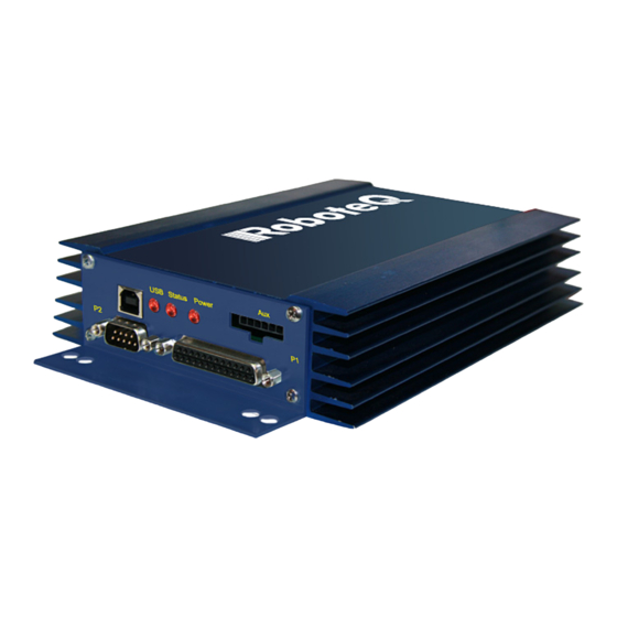
Roboteq's HDC2450 controller is designed to convert com-
mands received from a RC radio, Analog Joystick, wireless
modem, PC (via RS232 or USB) or microcomputer into high
voltage and high current output for driving one or two DC
motors. Designed for maximal ease-of-use, it is delivered with
all necessary cables and hardware and is ready to use in min-
utes.
The controller features a high-performance 32-bit microcom-
puter and quadrature encoder inputs to perform advanced
motion control algorithms in Open Loop or Close Loop (Speed
or Position) modes. The HDC2450 features a high number of
Analog, Pulse and Digital I/Os which can be remapped as com-
mand or feedback inputs, limit switches, or many other func-
tions. The controller's two motor channels can either be
operated independently or mixed to set the direction and rota-
tion of a vehicle by coordinating the motion of each motor.
Numerous safety features are incorporated into the controller
to ensure reliable and safe operation. The controller's operation
can be extensively automated and customized using Basic Lan-
guage scripts. The controller can be reprogrammed in the field
with the latest features by downloading new operating soft-
ware from Roboteq.
Applications
•
Industrial Automation
•
Tracking, Pan & Tilt systems
•
Terrestrial and Underwater Robotic Vehicles
•
Automatic Guided Vehicles
•
Police and Military Robots
•
Flight simulators
•
Telepresence Systems
•
Animatronics
HDC2450 Motor Controller Datasheet
Features List
•
USB, RS232, 0-5V Analog, or Pulse (RC radio) command
modes
•
Auto switch between USB, RS232, Analog, or Pulse based
on user-defined priority
•
Built-in high-power power drivers for two brushed DC
motors at up to 150A output per channel
•
Full forward & reverse control on each channel. Four quad-
rant operation. Supports regeneration
•
Operates from a single 10V-50V power source
•
Programmable current limit for each channel up to 2x150A
for protecting controller, motors, wiring and battery.
•
Up to 11 Analog Inputs for use as command and/or feed-
back
•
Up to 6 Pulse Length, Duty Cycle or Frequency Inputs for
use as command and/or feedback
•
Up to 21 Digital Inputs for use as Deadman Switch, Limit
Switch, Emergency stop or user inputs
•
Dual Quadrature Encoder inputs with 32-bit counters
•
8 general purpose 24V, 1A output for brake release or
accessories
•
Custom scripting in Basic language. Execution speed
50,000+ lines per second
•
Selectable min, max, center and deadband in Pulse and
Analog modes
•
Selectable exponentiation factors for each command
inputs
•
Trigger action if Analog, Pulse or Encoder capture are out-
side user selectable range (soft limit switches)
•
Open loop or closed loop speed control operation
•
Closed loop position control with analog or pulse/fre-
quency feedback
HDC2450
1
Advertisement
Table of Contents

Related Manuals for RoboteQ HDC2450


Summary of Contents for RoboteQ HDC2450
- Page 1 Open Loop or Close Loop (Speed • Operates from a single 10V-50V power source or Position) modes. The HDC2450 features a high number of • Programmable current limit for each channel up to 2x150A Analog, Pulse and Digital I/Os which can be remapped as com- for protecting controller, motors, wiring and battery.
-
Page 2: Orderable Product References
Orderable as single channel version up to 300A • Stall detection and selectable triggered action if Amps is outside user-selected range Orderable Product References TABLE 1. Reference Number of Channels Amps/Channel Volts HDC2450 HDC2450S HDC2450 Motor Controller Datasheet Version 1.2. July 20, 2010... -
Page 3: Power Wires Identifications And Connection
Note 2 VMot/Red Motor 2 VMot/Red Emergency Green/M2- Note 4 Cut-off Switch Note 5 Ground/Black Earth Tab Ground/Black I/O Connector Main Battery Note 6 Do not Connect! FIGURE 9. Powering the controller. Thick lines identify MANDATORY connections HDC2450 Motor Controller Datasheet... -
Page 4: Important Warning
Pin assignment is found in the table below. Auxiliary Connector USB connect, Power and Status LEDs (Reserved) Connector Communication and I/O Connectors FIGURE 10. Front Controller Layout HDC2450 Motor Controller Datasheet Version 1.2. July 20, 2010... - Page 5 DOUT4 DIN15 Unused DOUT5 DIN16 Unused DOUT6 DIN17 Status LED ANA5 DIN5 Unused ANA6 DIN6 Unused ANA7 DIN7 Unused ANA8 DIN8 ENC2B Unused ANA9 DIN9 ENC2A Unused ANA10 DIN10 ENC1B Unused ANA11 DIN11 ENC1A Unused 5VOut HDC2450 Motor Controller Datasheet...
-
Page 6: Default I/O Configuration
RC Pulse, 3-Analog. If needed, use the Roborun+ PC Utility to change the pin assignments and the command pri- ority order. RC Ch1 RC Ch2 Pot 1 Pot 2 Ext. Status LED RS232 TxOut Motor 2 RxIn Motor 1 Ground FIGURE 13. Factory default pins assignment HDC2450 Motor Controller Datasheet Version 1.2. July 20, 2010... -
Page 7: Status Led Flashing Patterns
External voltage applied to Rx/Tx pins Volts Case Temperature Case Humidity Case 100 (2) Note 1: Maximum regeneration voltage in normal operation. Never inject a DC voltage from a battery or other fixed source Note 2: Non-condensing HDC2450 Motor Controller Datasheet... -
Page 8: Power Stage Electrical Specifications (At 25Oc Ambient)
Note 10: Controller will stop until restarted in case of short circuit detection Note 11: Sensitivity selectable by software Note 12: Factory default value. Time in ms for power to go from 0 to 100% HDC2450 Motor Controller Datasheet Version 1.2. July 20, 2010... -
Page 9: Command, I/O And Sensor Signals Specifications
RS232 Watchdog timeout Rx pin 1 (3) 65000 Note 1: May be adjusted with configuration program Note 2: 115200, 8-bit, no parity, 1 stop bit, no flow control Note 3: May be disabled with value 0 HDC2450 Motor Controller Datasheet... -
Page 10: Thermal Specifications
(mm) Power Wire Gauge Wire Power Wire Diameter Outside diameter 0.26 (6.6) inches (mm) 1.60" (40 mm) 4.00" (102 mm) 5.50" (140 mm) FIGURE 16. HDC2450 front view and dimensions HDC2450 Motor Controller Datasheet Version 1.2. July 20, 2010... - Page 11 Electrical Specifications 0.25" (6.3 mm) 7.00" (177.8 mm) 8.00" (203 mm) 9.00" (228.6 mm) FIGURE 17 . HDC2450 top view and dimensions HDC2450 Motor Controller Datasheet...
- Page 12 HDC2450 Motor Controller Datasheet Version 1.2. July 20, 2010...
Need help?
Do you have a question about the HDC2450 and is the answer not in the manual?
Questions and answers