Sign In
Upload
Manuals
Brands
RoboteQ Manuals
Controller
AX3500
RoboteQ AX3500 Manuals
Manuals and User Guides for RoboteQ AX3500. We have
3
RoboteQ AX3500 manuals available for free PDF download: User Manual, Quick Start Manual, Specification Sheet
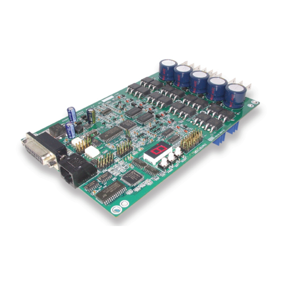
RoboteQ AX3500 User Manual (180 pages)
Dual Channel High Power Digital Motor Controller
Brand:
RoboteQ
| Category:
Controller
| Size: 3 MB
Table of Contents
Revision History
2
Table of Contents
3
AX3500 Quick Start
11
What You will Need
11
Locating Switches, Wires and Connectors
12
Connecting to the Batteries and Motors
13
Connecting the R/C Radio
14
Powering on the Controller
15
Button Operation
16
Default Controller Configuration
17
Checking and Changing Configurations
17
Connecting the Controller to Your PC Using Roborun
18
Obtaining the Controller's Software Revision Number
19
Exploring Further
20
AX3500 Motor Controller Overview
21
Product Description
21
Technical Features
22
Connecting Power and Motors to the Controller
25
Connecting Power
25
Controller Power
26
Powering the Controller Using the Motor Batteries
28
Using a Backup Battery
29
Power Fuses
30
Wire Length Limits
30
Electrical Noise Reduction Techniques
31
Power Regeneration Considerations
31
Overvoltage Protection
32
Undervoltage Protection
32
Using the Controller with a Power Supply
32
General Operation
35
Basic Operation
35
Input Command Modes
35
Selecting the Motor Control Modes
36
Open Loop, Separate Speed Control
36
Open Loop, Mixed Speed Control
36
Closed Loop Speed Control
37
Close Loop Position Control
37
Current Limit Settings
38
Continuous and Extended Current Limitation
38
Temperature-Based Current Limitation
39
Surge Current Protection
39
Regeneration Current Limiting
40
Programmable Acceleration
40
Command Control Curves
42
Left / Right Tuning Adjustment
43
Emergency Shut down Using Controller Switches
44
Emergency Stop Using External Switch
45
Inverted Operation
45
Special Use of Accessory Digital Inputs
46
Using the Inputs to Activate the Buffered Output
46
Using the Inputs to Turn Off/On the Power MOSFET Transistors
46
Self-Test Mode
46
Connecting Sensors and Actuators to Input/Outputs
49
AX3500 Connections
49
Ax3500'S Inputs and Outputs
51
I/O List and Pin Assignment
52
Connecting Devices to Output C
53
Connecting Switches or Devices to Input F
54
Connecting Switches or Devices to Estop/Invert Input
54
Connecting Position Potentiometers to Analog Inputs
55
Connecting Tachometer to Analog Inputs
56
Connecting External Thermistor to Analog Inputs
57
Using the Analog Inputs to Monitor External Voltages
58
Connecting User Devices to Analog Inputs
59
Internal Voltage Monitoring Sensors
60
Internal Heatsink Temperature Sensors
60
Temperature Conversion C Source Code
61
Normal and Fault Condition LED Messages
63
Use of the LED Display
63
SECTION 6 Normal and Fault Condition LED Messages
63
Motor Direction Status
64
Fault Messages
65
No Control
65
Emergency Stop
66
Self-Test Display
66
R/C Operation
67
Mode Description
67
SECTION 7 R/C Operation
67
Selecting the R/C Input Mode
68
Typical Wiring
68
Connector I/O Pin Assignment (R/C Mode)
69
R/C Input Circuit Description
70
Supplied Cable Description
71
Cabling to R/C Receiver Using Full Opto-Isolation
72
Cabling to R/C Receiver with Partial Opto-Isolation
73
Powering the Radio from the Controller
74
Operating the Controller in R/C Mode
76
Reception Watchdog
77
R/C Transmitter/Receiver Quality Considerations
77
Joystick Deadband Programming
78
Command Control Curves
79
Left/Right Tuning Adjustment
79
Joystick Calibration
79
Automatic Joystick Calibration
80
Data Logging in R/C Mode
81
Serial (RS-232) Controls and Operation
83
Use and Benefits of RS232
83
Connector I/O Pin Assignment (RS232 Mode)
84
Cable Configuration
85
Extending the RS232 Cable
85
Communication Settings
86
Establishing Manual Communication with a PC
86
Entering RS232 from R/C or Analog Mode
87
Data Logging String in R/C or Analog Mode
87
RS232 Mode if Default
88
RS232 Commands Set
88
Set Motor Command Value
88
Set Accessory Outputs
89
Query Power Applied to Motors
89
Query Amps Consumed by Motors
90
Query Analog Inputs
90
Query Heatsink Temperatures
91
Query Battery Voltages
91
Query Digital Inputs
91
Read and Modify Controller Settings
92
Apply Parameter Changes
93
Reset Controller
93
Optical Encoder Commands
93
Commands Acknowledge and Error Messages
93
Character Echo
93
Command Acknowledgement
93
Command Error
94
Watchdog Time-Out
94
RS-232 Watchdog
94
RS232 Accessible Parameter Table
95
Automatic Switching from RS232 to RC Mode
97
Analog and R/C Modes Data Logging String Format
98
Data Logging Cables
99
Decimal to Hexadecimal Conversion Table
100
Analog Control and Operation
103
Mode Description
103
Connector I/O Pin Assignment (Analog Mode)
104
Connecting to a Voltage Source
105
Connecting a Potentiometer
105
Selecting the Potentiometer Value
106
Analog Deadband Adjustment
107
Power-On Safety
108
Under Voltage Safety
108
Data Logging in Analog Mode
108
Closed Loop Position Mode
111
Mode Description
111
Selecting the Position Mode
111
Position Sensor Selection
112
Sensor Mounting
112
Potentiometer Wiring
113
Using Optical Encoders in Position Mode
113
Sensor and Motor Polarity
113
Adding Safety Limit Switches
115
Using Current Limiting as Protection
116
Control Loop Description
116
PID Tuning in Position Mode
118
Closed Loop Speed Mode
119
Mode Description
119
Selecting the Speed Mode
119
Using Optical Encoder for Speed Feedback (AX2850 Only)
120
Tachometer or Encoder Mounting
120
Tachometer Wiring
120
Speed Sensor and Motor Polarity
121
Adjust Offset and Max Speed
122
Control Loop Description
122
PID Tuning in Speed Mode
123
Installing, Connecting and Using the Encoder Module
125
Optical Incremental Encoders Overview
125
Recommended Encoder Types
126
Connecting the Encoder
127
Motor - Encoder Polarity Matching
128
Voltage Levels, Thresholds and Limit Switches
128
Wiring Optional Limit Switches
129
Using the Encoder Module to Measure Distance
130
Using the Encoder to Measure Speed
131
Using the Encoder to Track Position
132
RS232 Communication with the Encoder Module
133
RS232 Encoder Command Set
134
Read Encoder Counter
134
Set/Reset Encoder Counters and Destination Registers
135
Read Speed
135
Read Distance
136
Read Speed/Distance
136
Read Encoder Limit Switch Status
136
Read / Modify Encoder Module Registers and Parameters
137
Register Description
139
Encoder Hardware ID Code
139
Switch Status
140
Speed or Distance 1
140
Counter Read/Write Mailbox
140
Counter 1 and 2
140
Destination Register 1 and 2
140
Distance 1 and 2
140
Speed 1 and 2
141
Time Base 1 and 2
141
Encoder Threshold
141
Counter Read Data Format
141
Encoder Testing and Setting Using the PC Utility
142
Encoder Module Parameters Setting
143
Exercising the Motors
144
Viewing Encoder Data
144
Updating the Encoder Software
144
RC Pulses Output
147
RC Pulse Output Overview
147
SECTION 13 RC Pulses Output
147
Connector Location and Pinout
148
Connecting Servos and Slave Controllers
148
Pulse Timing Information
149
RS232 Commands
150
RC Channel Testing Using the PC Utility
151
Configuring the Controller Using the Switches
153
Programming Methods
153
Programming Using Built-In Switches and Display
153
Entering Programming Mode
154
Changing Parameters
155
The Special Case of Joystick Calibration
155
Restoring Factory Defaults
156
Exiting the Parameter Setting Mode
156
Programmable Parameters List
156
Using the Roborun Configuration Utility
159
System Requirements
159
Downloading and Installing the Utility
159
Connecting the Controller to the PC
160
Roborun Frame, Tab and Menu Descriptions
161
Getting On-Screen Help
162
Loading, Changing Controller Parameters
162
Controls Settings
163
Power Settings
164
Analog or R/C Specific Settings
165
Closed Loop Parameters
166
Viewing the Parameters Summary
166
Optical Encoder Operation
167
Running the Motors
167
Logging Data to Disk
170
Connecting a Joystick
171
Viewing and Logging Data in Analog and R/C Modes
172
Loading and Saving Profiles to Disk
172
Operating the AX3500 over a Wired or Wireless LAN
172
Updating the Controller's Software
174
Creating Customized Object Files
174
Mechanical Specifications
177
Mechanical Dimensions
177
Mounting Considerations
178
Thermal Considerations
178
Wire Dimensions
179
Weight
179
Advertisement
RoboteQ AX3500 Quick Start Manual (12 pages)
Dual Channel High Power Digital Motor Controller
Brand:
RoboteQ
| Category:
Controller
| Size: 1 MB
Table of Contents
Quick Start
2
Important Safety Warnings
2
This Product Is Intended for Use with Rechargeable Batteries
2
Locating Switches and Connectors
3
Connecting to the Batteries and Motors
4
Important Warning
4
Using the Power Control Tab
5
Connecting the R/C Radio
5
Powering on the Controller
6
Button Operation
7
Default Controller Configuration
8
Checking and Changing Configurations
8
Connecting the Controller to Your PC Using Roborun
9
Obtaining the Controller's Software Revision Number
10
Exploring Further
11
RoboteQ AX3500 Specification Sheet (2 pages)
Dual Channel Forward/Reverse Digital Robot Controller with Optical Encoder Inputs
Brand:
RoboteQ
| Category:
Computer Hardware
| Size: 0 MB
Advertisement
Advertisement
Related Products
RoboteQ Dual Channel Digital Motor Controller AX500
RoboteQ Dual Channel Digital Motor Controller AX1500
RoboteQ AX2850
RoboteQ Dual Channel Digital Motor Controller AX2550
RoboteQ CANBus Series
RoboteQ CANOpen
RoboteQ FBL2360
RoboteQ FBL2360A
RoboteQ FBL2360E
RoboteQ FBL2360ES
RoboteQ Categories
Controller
Recording Equipment
Computer Hardware
Network Hardware
Control Unit
More RoboteQ Manuals
Login
Sign In
OR
Sign in with Facebook
Sign in with Google
Upload manual
Upload from disk
Upload from URL